EP0151027A2 - Stapelhalter und Zuführvorrichtung - Google Patents
Stapelhalter und Zuführvorrichtung Download PDFInfo
- Publication number
- EP0151027A2 EP0151027A2 EP85300602A EP85300602A EP0151027A2 EP 0151027 A2 EP0151027 A2 EP 0151027A2 EP 85300602 A EP85300602 A EP 85300602A EP 85300602 A EP85300602 A EP 85300602A EP 0151027 A2 EP0151027 A2 EP 0151027A2
- Authority
- EP
- European Patent Office
- Prior art keywords
- cam
- envelope
- stack
- axis
- hopper
- Prior art date
- Legal status (The legal status is an assumption and is not a legal conclusion. Google has not performed a legal analysis and makes no representation as to the accuracy of the status listed.)
- Granted
Links
Images


Classifications
-
- B—PERFORMING OPERATIONS; TRANSPORTING
- B65—CONVEYING; PACKING; STORING; HANDLING THIN OR FILAMENTARY MATERIAL
- B65H—HANDLING THIN OR FILAMENTARY MATERIAL, e.g. SHEETS, WEBS, CABLES
- B65H3/00—Separating articles from piles
- B65H3/08—Separating articles from piles using pneumatic force
- B65H3/0808—Suction grippers
- B65H3/085—Suction grippers separating from the bottom of pile
- B65H3/0858—Suction grippers separating from the bottom of pile this action resulting merely in a curvature of each article being separated
- B65H3/0866—Suction grippers separating from the bottom of pile this action resulting merely in a curvature of each article being separated the final separation being performed between rollers
-
- B—PERFORMING OPERATIONS; TRANSPORTING
- B65—CONVEYING; PACKING; STORING; HANDLING THIN OR FILAMENTARY MATERIAL
- B65H—HANDLING THIN OR FILAMENTARY MATERIAL, e.g. SHEETS, WEBS, CABLES
- B65H1/00—Supports or magazines for piles from which articles are to be separated
- B65H1/04—Supports or magazines for piles from which articles are to be separated adapted to support articles substantially horizontally, e.g. for separation from top of pile
- B65H1/06—Supports or magazines for piles from which articles are to be separated adapted to support articles substantially horizontally, e.g. for separation from top of pile for separation from bottom of pile
Definitions
- This invention pertains to hoppers and feeders, and particularly to hoppers from which envelopes are extracted for use in a postal preparatory processing machine, such as an insertion machine or the like.
- One or more suction mechanisms positioned just below the plane of the breaker plate but between the breaker plate front edge and the front vertical wall, function to eflect downwardly at least a portion of the bottom most envelope which is lying on and overhanging the breaker plate of the hopper) so that the bottom-most envelope can be engaged by appropriate gripper means situated proximate the front of the hopper; be extracted from the hopper; and, be transported away from the hopper for downstream postal preparatory processing.
- small envelopes are loaded with their major dimension parallel to the front vertical wall, and hence parallel to the breaker plate front edge. Since the breaker plate front edge is separated from the front vertical wall by a distance which is on the order of one-half the minor dimension of the small envelopes, a considerable amount of each small envelope overhangs the breaker plate front edge relative to the entire small envelope.
- the small envelopes tend not to lie horizontally, but instead tend to tip over the breaker plate front edge so that the envelopes in the stack are inclined at an acute angle to the breaker plate.
- the inclined plurality of envelopes cause a jam when the gripper means attempts to extract the bottom-most envelope.
- One type of prior art special hopper comprises two sets of vertical rods, each set positioned in parallel relationship along the major dimension of a space corresponding to a small envelope. Each set of rods has mounted thereto a horizontal ledge which faces and is coplanar with the ledge of the other set of rods. The major dimensional edges of a bottom-most envelope rest upon these ledges. Other envelopes are stacked upon the bottom-most envelope and between the vertical rods. A mechanism is situated below the plane of the ledges.
- the shuttle feed mechanism includes an essentially rectangular horizontal plate which reciprocates in its horizontal plane in a direction from the back of the hopper toward the front of the hopper.
- One of the concerns on the leading edge of the shuttle plate is truncated to define a triangular space.
- a stationary first suction mechanism lies below the triangular space. The stationary first suction mechanism serves to deflect downwardly a corresponding corner of the bottom-most small envelope.
- a second suction mechanism situated on the other corner of the leading edge of the shuttle place also engages the bottommost envelope and travels with the shuttle plate as the plate and bottommost envelope held by the shuttle plate are advanced to the front of the hopper by the motion of the reciprocating shuttle plate.
- the appropriate gripper means engages the advanced envelope in like manner as described above and transports the advanced envelope away from the hopper. While the shuttle plate of this second type of envelope hopper functions well to extract small envelopes, the shuttle plate does not have enough suction to both attract a large envelope and cause the large envelope to reciprocate therewith in the direction of the gripper means.
- An envelope hopper to be described below is capable of selectively handling stacks of short envelopes, stacks of long envelopes, or stacks of envelopes of intermediate dimensions.
- the envelope stack rests on a table frame in such a manner that at least a portion of a bottommost envelope overhangs a breaker plate edge.
- suction cups rise from below a breaker plate to attract the underside of the overhanging envelope and then fall to deflect the attracted envelope. Rotating arcuate surfaces of segmented rollers thereafter make contact with the underside of the deflected envelope.
- Cooperating rollers are pivoted into a position to contact the upperside of the deflected envelope, to engage the deflected envelope between the rollers and the driven segmented roller, and to apply a pressure which facilitates displacement of the envelope from the stack by the application of rotational motion from the segmented roller.
- the extent to which the envelope is fed from the stack and into awaiting gripper jaw is dependent upon control means which govern the motion of the rollers, as well as upon means provided to selectively adjust the distance separating the hopper from transportation discharge means.
- the hopper is further provided with adjustable stack alignment guide means for accommodating envelope stacks of differing sizes.
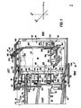
- Fig. 1 shows a hopper and feed apparatus 20 which comprises right vertical side frame member 22 and a left vertical side frame member 24; an essentially horizontally-oriented stack-support table frame member 26; and, an essentially horizontally-oriented discharge table 28.
- the stack support table frame 26 has a horizontal breaker plate 30 mounted thereon.
- the breaker plate 30 has an edge 32 which is parallel to the Y axis as shown in Fig. 1.
- stack alignment guide means mounted in a manner described more particularly herein on the table frame 26 are stack alignment guide means denoted generally as 40.
- the stack alignment guide means comprise left side guide means 42; right side guide means 44; and, rear guide means 46.
- the discharge table 28 has a table top 50 along which articles, such as envelopes, are transported after being fed from the hopper.
- a plurality of gripper jaws 52 are positioned at periodic intervals on an indexed chain 54.
- Chain 54 is driven in timed relationship with other facets of the hopper 20 by a sprocket 55 (see Fig. 3).
- the table top 50 has a channel 56 formed therein to accommodate the chain 54 in the elevated portion of its path of travel along the table top 50.
- the chain 54 is driven so as to transport envelopes away from the hopper in the direction shown by arrow 58.
- Envelope opening means including a plough 59 are positioned on the table top 50 for opening envelopes which are fed from the hopper 20 and transported by chain 54.
- the top 50 of discharge table 28 also has a plurality of rectangular-like peninsula portions 60a, 60b, 60c, 60d, and 60e which extend generally in the direction toward the stack-support table frame 26 of the hopper 20.
- each peninsula 60 extends to a point just shy of the breaker plate edge 32 in the sense of the X axis.
- the distance along the X axis separating the peninsulas 60 and the breaker plate edge 32 is selectively adjustable.
- the table top 50 and peninsulas 60 extending therefrom are not as high in the sense of the Z axis as the stack-support table frame 26, so that a vertical drop exists between the breaker plate 30 and the peninsulas 60.
- the openings 62a and 62d are sized to accommodate deflection means, shown as sucker cups 64. As seen in hereinafter, the sucker cups are adapted to rotate upwardly into the plane of the breaker plate 30 and to attract thereto a portion of an envelope overhanging the breaker plate edge 32.
- the openings 62b, 62c, and 62e are sized to accommodate segmented roller means 66, three such segmented rollers (66a, 66b, and 66c) being shown in Fig. 1. The structure and operation of these segmented roller means 66 are described below in further detail.
- the opening 62d also accommodates a portion of the chain 54 during a portion of its path of travel in which the chain 54 travels between peninsulas 60d and 60e.
- shaft means 70 including a first shaft segment 70a and a second shaft segment 70b.
- rollers 72 which, as seen hereinafter, cooperate with segmented rollers 66. Accordingly, three such rollers 72 (namely, rollers 72a, 72b, and 72c) are shown in Fig. 1.
- the rollers 72 are suspended from the shaft means 70 by means hereinafter described for cooperation with the segmented rollers 66, the rollers 72 are free rollers and are not driven.
- Control means 80 is used to control the pivotal motion of rollers 72 about a pivot point or axis B.
- Shaft means 70 to which each roller 72 is attached is carried by a follower arm 82 included in the control means 80.
- shaft 70a is accommodated in an aperture on the left hand side (as seen in Fig. 2) of the distal portion of the follower arm 82 by a fastener 84.
- the follower arm 82 is rotatable about axis B in the directions depicted by arrow 86
- the follower arm 82 is connected to the side frame 22 by an appropriate fastener 88 along axis B in a manner which permits the follower arm 82 to pivot about axis B.
- the upper end of the follower arm 82 is biased towards a flange 90 integral with the side frame 22 by an appropriate biasing means, such as compression spring 92.
- the distal end of the follower arm.82 has mounted on the left side thereof the shaft 70a.
- a follower roller 96 On the right side of the distal end of the follower arm 82 is mounted a follower roller 96.
- a niche 98 is cut out of each vertical side frame member (such as member 22 as shown in Fig. 2) to accommodate the rocking motion of shaft 70a as governed by the control means 80.
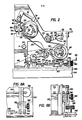
- the control means 80 further comprises cam means, particularly a split cam including a first cam 100 and a second cam 102.
- Cams 100 and 102 are mounted in side-by-side relationship and adapted to rotate about a common axis C.
- a circular timing sprocket 104 is positioned between the cam means and the right vertical sidewall 22 and is also adapted to rotate about the axis C.
- the cam 102 is outermost with respect to the axis C. That is, the first cam 100 is axially positioned between the timing sprocket 104 and the second cam 102.
- Each cam of the control means 80 has a surface or lobe thereon for controlling the movement of the rollers 72.
- Cam 100 has a cam surface 108 which controls the duration of the time in which the roller 72 travels in the counter-clockwise direction (as depicted by arrow 86) about axis B toward the counter- clockwise-rotating segmented roller 66.
- Cam 102 has a cam surface 110 which controls the duration of time in which the roller 72 travels in a clockwise direction (in the direction of arrow 86) about axis B away from the segmented roller 66.
- the follower roller 96 follows whichever of the cams 100 and 102 has a greater radial dimension between the roller 96 and axis C.
- the cams 100 and 102 are so oriented that the follower roller 96 on follower arm 82 rides on cam surface 110 of cam 102 after riding on cam surface 108 of cam 100.
- the cam means included in control means 80 rotate in the counter-clockwise direction.
- the control means 80 also include means for adjusting the angular orientation of the cam 102 about the axis C.
- Cam 102 has two arcuate channels 114 at equal radial distances from the axis C. Each arcuate channel 114 extends through the width of cam 102. Each channel 114 is adapted to receive therein cam fastening or locking means 116 which extend through each channel 114.
- Each fastener 116 has a polygonal (preferably hexagonal) shaped head adapted to bear against the side of cam 102.
- Each fastener 116 further has a threaded shaft which is received in an appropriate counter-threaded bore properly aligned in cam 100.
- the cam means 80 rotates in a counter-clockwise direction.
- the sprocket 104 rotates in a counter-clockwise direction since it is connected to an intermediate driving means 120 by transmission means such as chain 122.
- the intermediate driving means 120 comprises a circular sprocket 124 adapted to engage the chain 122.
- sprocket l24 is semi-circumferentially embraced by chain 122.
- the sprocket 124 is mounted on a counter-clockwise rotating shaft 126. Shaft 126 rotates about axis D.
- the tension on chain 122 is adjustable by selecting an appropriate position for a tensioning sprocket 128.
- Sprocket 128 is mounted on a tensioning arm 130 adapted to pivot about pivot point 132 so as to selectively travel in an arcuate path as indicated by arrow 134.
- An arcuate channel 136 on the tensioning arm 130 receives a fastening means or locking means 138 which, when tightened, secures the tensioning arm 130 in a fixed position.
- the intermediate driving means 120 further comprises a second sprocket 140 also mounted on the shaft 126.
- Sprocket 140 is semi-circumferentially engaged by transmission means such as chain 142 which connects the intermediate driving means 120 with primary driving means 143 (See Fig. 9).
- Tensioning adjustment means (generally indicated as 144) for chain 142 is described further herein.
- Means for adjusting the angular orientation of cam 100 about axis C comprises a clamp 150 which is used to selectively lock sprocket 124 to the shaft 126 so that the sprocket 124 (and hence the chain 122 and the cam means) rotates as shaft 126 rotates.
- Fastening or locking means 152 enable the clamp 150 to be selectively loosened and tightened with respect to the shaft 126.
- Clamp 150 is secured to the sprocket 124 by suitable fastening means (such as fastener 154).
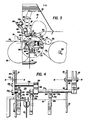
- Fig. 3 shows in broken lines the follower arm which pivots about axis B.
- the follower arm 82 carries the shaft segment 70a.
- the shaft 70a (and hence the roller 72) moves in the direction of arrow 86.
- Fig. 3 further shows a roller 72 which cooperates with a corresponding segmented roller 66.
- the roller 72 is mounted for free rotation about a shaft 160.
- Each end of the shaft 160 is engaged by arms of a bracket 162.
- a fastener 164 locks the bracket 162 onto shaft 70a.
- the bracket 162 is essentially L-shaped.
- the base of the bracket 162 is inclined slightly upwardly at an acute angle with respect to the horizontal.
- shaft means 70 comprise shaft segment 70a and segment 70b. Segment 70b is slightly offset from segment 70a and coupled thereto by a coupling bracket 166. Coupling bracket 166 is secured to the shaft 70b by appropriate locking means, such as fastener 168. Shaft segment 70b is offset from segment 70a so that a clearance 170 is provided between roller 72b and 72c. The clearance 170 facilitates the extraction of an envelope from the hopper by gripper jaw 52 in such a manner that envelope opening means positioned downstream on the table 50 can commence the opening the envelope flap without obstructions which would otherwise be presented by a shaft in the clearance 170.
- Fig. 3 also shows one of the segmented rollers 66.
- Segmented rollers 66a and 66b are mounted as hereinafter described on a common horizontally-extending shaft 172.
- roller 66c is mounted on a separate horizontally-extending shaft which is coaxial with shaft 172.
- a gap in the neighborhood of the opening 62d separates the shafts upon which rollers 66 are mounted to accommodate the chain 54.
- shaft 172 has a sprocket 174 mounted thereon.
- a driving chain 175 extends semi-circumferentially around the sprocket 174 and also semi-circumferentially around a third sprocket 176 mounted on the rotating shaft 126 having axis D.
- the diameters of the sprockets 174 and 176 are relatively sized so that the sprocket 174 rotates twice for each revolution of sprocket 176.
- a tensioning sprocket 178 similar in function and mounting to sprocket 128 described earlier, maintains an appropriate tension on the chain 175.
- shaft upon which roller 66c is mountd has a sprocket analogous to sprocket 174 mounted thereon, so that a chain analogous to chain 175 can extend therearound and around a sprocket like sprocket 176 on shaft 126.
- the segmented roller 66 comprises an essentially C-shaped portion 182 of a bracket 184 locked to shaft 172 by a fastener or locking means 188.
- Shaft 172 has axis A as its axis rotation.
- the bracket 184 has an arm perpendicularly extending therefrom.
- the bracket 184 also has an extension member 192 integral with the C-shaped portion 182 thereof.
- the extension member 192 is adapted to receive a fastener 194.
- the fastener 194 connects the bracket 184 in pivotal relationship to a circular segment member 196.
- a first end of the segment member 196 is counter-threaded to receive a stop limiting means, particularly a threaded fastener 198.
- the position of a nut on the threaded fastener 198 determines the distance separating the segment portion 196 and the bracket 184 at the stop means 198.
- An opposite end of the segment member 196 has resilient means such as compression spring 200 connected thereto to bias the segment member 196 to the perpendicular arm 190 of the bracket 184.
- the segment member 196 has an arcuate surface 202.
- segment member 196 is pivotable about a fastener 194, it is generally urged by the stop limiting means and compression spring 200 to a position whereby arcuate surface 202 travels the circular path about axis A.
- the compression spring 200 thus serves to protect against overloads in the event of multiple feeds or the like.
- the arcuate surface 202 When the segment member 196 is so positioned that the arcuate surface 202 generally travels a circular path about the axis A of shaft 172, the arcuate surface 202 is seen as subtending an angle of approximately 75 * with respect to the axis A.
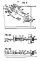
- Fig. 4 shows a rotating arm 210 mounted on the opposite vertical side frame 24 and adapted to pivot about the axis B.
- the arm 210 is mounted to the sidewall 24 by a fastener 212 which permits rotation of the arm 210 about axis B.
- the arm 210 resembles the follower arm 82 in that it is adapted to receive shaft means 70 and a spring somewhat similar to compression spring 92 on arm 82.
- the arm 210 is adapted to receive in an aperature thereof shaft segment 70b and to secure the same thereto by fastener 214.
- the distal portion of the arm 210 has a horizontal extension 216, which functions much in the manner of shaft segment 70a and is coaxial therewith, has roller 72 secured thereto by a bracket 164 in the manner described above.
- Fig. 5 illustrates deflection means associated with the hopper 20.
- the deflection means includes a pair of sucker cups 64, one of which is shown in Fig. 5.
- Each sucker cup 64 is mounted on a stem 220 connected by flexible tubing 222 to a vacuum valve (unillustrated).
- the stem 220 has a threaded exterior.
- the stem 220 extends through a circular opening in each of two arms of a first end of a bracket 224.
- the arms of the first end of the bracket 224 are separated by a gap which accommodates an adjustment ring 226.
- the adjustment ring 226 has its interior diameter counter-threaded to ride on stem 220. Turning of the adjustment ring 226 is used to adjust the position of the bracket 224 relative to the stem 220.
- the second end of the bracket 224 is configured as a clamp and locked by fastener 228 onto a horizontal shaft 230.
- the horizontal shaft 230 runs essentially the width of the table 26 as seen in Fig. 1.
- an end of the shaft 230 is held by a bracket 232 to a pivot point 234.
- the pivot point 234 on each side of the table 26 is aligned in all directions with the breaker plate edge 32 as seen in Fig. 5.
- the positioning of the pivot point 234 in Fig. 1 relative to the breaker plate edge 32 has been slightly displaced to facilitate illustration of the bracket 232 and point 234.
- Shaft 230 is connected by a reciprocating arm 236 through the rotating shaft 126 described above.
- a second end of the arm 236 has a follower roller 238 mounted thereon.
- Roller 238 has a circumferential point thereof in contact with the circumference of a cam 240.
- the cam 240 is mounted on the shaft 126.
- Arm 236 has a slot along its major axis to accommodate the shaft 126 so that the arm 236 can reciprocate about the shaft 126 in the manner about to be described.
- Resilient biasing means 242 connected to a sidewall connection point 244 urges the arm 236 leftward as shown in Fig. 5 so that the sucker cup is in the position shown by the broken lines 64' when the surface 246 of cam 240 is in contact with the follower roller 238. Otherwise, when the essentially circular load portion of cam 240 contacts the roller 238, the arm 236 is driven toward the right and the cup 64 is in the position shown by the solid lines in Fig. 5.
- each vertical side frame member is a horizontally extending flange 250.
- Flange 250 and thus the hopper 20, is situated on a foundation support 252 which comprises a horizontally extending flange 254 and a vertical support wall 256.
- the foundation support 252 comprises part of an overall apparatus system in which the hopper 20 is included.
- the foundation support 252 is, in one embodiment, part of an automated in-line insertion machine which utilizes envelopes fed from the hopper 20.
- the foundation support 252 is so adapted that the position of the hopper 20 can be adjusted in either of the directions as indicated by the doubleheaded arrow 258. That is, hopper 20 and particularly the flange 250 is adapted to travel in the directions indicated by arrow 258.
- hopper 20 is restrained from travel along the Y axis by suitable means, including an unillustrated channel in flange 254 which extends along the X direction and is adapted to receive a complementary fitting tongue on hopper flange 250.
- Displacement of the hopper 20 in the direction of the arrow 258 as indicated in Fig. 9 adjusts the distance of strategic hopper elements with respect to the transportation means 54 and gripper jaws 52 carried thereon.
- displacement of the hopper 20 in the directions of arrow 258 changes the location of such elements as, for example, (1) the breaker plate edge 32, and (2) the segmented roller 66 and the rollers 72 which are used to pull deflected bottom-most articles from the breaker plate 30 and feed the same to the transport mechanism 54.
- Displacement of the hopper 20 in this manner is a further control on the extent to which an article such as an envelope is fed to an awaiting gripper jaw 52.
- Means 260 comprise one or more locking clamps 262 and a means 264 for translating rotational motion into linear displacement.
- the clamp 262 has a manually-engagable head and a threaded stem which extends through an aperture in the horizontal flange 254 of the foundation support 252 to selectively bear against the flange 250 of the hopper to lock the same in position. Loosening the clamp 262 permits an operator to adjust the means 264 so that the hopper 20 can be displaced in the directions of arrows 258.
- the means 264 include a first inverted L-shaped bracket 266 (which is secured to the base of the hopper 20 by appropriate threaded fasteners 268) and a second inverted L-shaped bracket 270 (which is secured to the surface 254 by appropriate fasteners 272).
- the brackets 266 and 270 have apertures in their upstanding members, the apertures being aligned in the sense of the X asis as shown in Fig. 1.
- the aperture of bracket 266 is adapted to receive a threaded stem 274 of a rotatable member 276.
- the aperature in the upstanding member of bracket 270 is of a somewhat larger diameter to accommodate a correspondingly enlarged diameter portion of the rotatable member 276.
- the rotatable member 276 is further provided with a manually-engageable head 278. Rotation of the head 278 of rotatable member 276 causes the rotation of the threaded stem 274. Inasmuch as the bracket 270 is stationary and prevents the rotatable member 276 from displacement in the direction of the X axis, the threaded relationship of the stem 274 and the aperture in the upstanding member of bracket 266 causes the entire hopper 20 to be displaced in the directions of arrow 258 so that the distances separating the structural mechanisms included in the hopper 20 are adjustable with respect to the discharge table 28, and particularly the transport means 54 including gripper jaws 52 associated therewith.
- the tension adjustment apparatus 144 includes a sprocket 290 rotatably mounted on an L-shaped arm 292.
- the arm 292 pivots about a point 294, the point 294 being fixed to the base of the hopper 20 by a pedestal 296.
- the end of the arm 292 which does not carry the sprocket 290 is adapted to carry a tension take-up linkage mechanism generally indicated as 298, also shown in Figs. 6A and 6B.
- the tension take-up mechanism 298 comprises a block 300 which has an aperture 302 extending horizontally therethrough. A shaft about which the block pivots extends through the aperture 302 and is engaged by the lower end of arm 292.
- Block 300 is also counter-threaded to engage a threaded first end of a connector member 304.
- the second end of the connector 304 extends through a central aperture of a plate 306.
- Plate 306 has three apertures aligned in the sense of the Y axis of Fig. 1.
- the two outer apertures on plate 306 recieve leg portions of an elongated essentially U-shaped threaded member 308.
- the ends of the legs of U-shaped threaded member 308 extend through a second plate 310 which, except for position of placement, is identical to the plate 306.
- the ends of the legs of the U-shaped member 306 are secured to the plate 310 by appropriate fasteners 312.
- a bent portion of the U-shaped threaded member 308 is engaged by a crook member 314.
- a stem portion 316 of the crook 314 is threaded and is received in an aperture of a pedestal 318.
- An internally counter-threaded knob 320 travels on the threaded stem 316 of crook 314.
- Manual adjustment of the knob 320 causes the crook member to travel in either of the directions indicated by arrow 322. That is, manual rotation of the knob 320 is translated into linear motion along the direction of the X axis as seen in Fig. 1. For example, clockwise rotation of the knob 320 pulls the crook member 314 rightwardly, pulling the U-shaped member 308, connector member 304, and block 300 rightwardly.
- Figs. 7, 8A, and 8B further illustrates stack alignment guide means 40.
- the rear guide means 46 operates in conjunction with the slot 330 formed in the plane of the table 26.
- the slot 330 is an elongated slot extending in a direction essentially parallel to the X axis as seen in FIG. 1.
- a channel 332 is formed beneath the table top 26 in such a manner as to extend under the slot 330 throughout its length.
- the slot 330 -and channel 332 formed thereunder are adapted to accommodate the stem 334 of a lock member 336 included in the rear guide means 46.
- the lock member has a manually-engageable head 338 which is rotatable to selectively tighten and thus secure a block member 340 (with which lock member 336 travels) against the table top at selected desired locations.
- Block 340 is essentially L-shaped with a base leg extending essentially horizontally.
- the base leg of the block 340 has a vertically extending aperture through which the stem 334 of lock member 336 extends, stem 334 extending further through the slot 330 and into the channel 332 to bear against a horizontal bottom surface of the channel 332.
- An upright leg of the block 340 has an elevated horizontal rail 342 connected thereto. One end of the rail 342 terminates just short of the left side guide means 42; the other end of the rail 342 terminates in a channel in the right guide means 44.
- the right side guide means 44 includes an elevated horizontally-extending member 350 which is held aloft by a traveling block 354 adapted to ride on the rail 342 of the rear guide means 46.
- Horizontal- extending member 350 supports the vertical guide post 352.
- the traveling block 354 has a channel formed in a depending portion thereof to fit over the rail 342 so that the right guide means 44 can travel along the rail 342 in the direction of the Y axis (that is, either in the direction indicated by arrow 356 or arrow 358).
- Locking means 360 including a manually-engageable rotating head on a threaded shaft are received in an aperture of the block 354 so that the head of the shaft can extend into the channel formed by the block 354 and bear against the rail 342.
- the locking means 360 can thus be selectively loosened so that translation of the right guide means 44 in the manner described above can take place, and thereafter can be locked to secure the right guide means 44 in position. Also included in the right guide means 44 is a vertically extending post 362 secured to the block 354 and oriented to form a guide surface facing the front of the hopper 20.
- the left side alighment guide means 42 comprises two vertically extending posts 370 and 372 arranged in the corner configuration and coupled together by a bracket 374.
- the bracket 374 allows the left side alignment guide means 42 to travel along an elevated horizontal rail 376.
- a first end of the rail 376 is connected to the left vertical side frame member 24 by appropriate fasteners; the second end of the rail 376 is held elevated by a stationary post 378.
- Locking means 380 including a manually-actuatable knob on a threaded stem is used to selectively tighten the bracket and post assembly to the rail 376 at a desired location along the rail 376.
- the envelope stack alignment guide means 40 are adjusted to accommodate the size of envelopes to be included in the stack which is to rest on the stack-support table frame 26.
- the respective guide means including left side guide means 42, right side guide means 44, and rear guide means 46 have heretofore been in the position shown in FIG. 1 to accommodate a large envelope LE whose dimensions are shown in broken lines in FIG. 1.
- the stack alignment guide means 40 included in the hopper 20 are adjusted to accommodate a stack of small envelopes SE in the following manner:
- the left side alignment guide means 42 is first adjusted to accommodate a corner of the envelope by loosening the locking means 380 associated therewith, sliding the guide means 42 (if necessary) in either of the directions indicated by arrows 382 or 384 to the desired position along the rail 376; and, tightening the locking means 380.
- the knob 336 on the rear guide 46 is likewise loosened; the block 340 (and hence the entire rear guide means 46) is moved either in the direction of arrows 386 or 388 with the stem 334 of the lock member 336 traveling in the slot 330 until the desired position with respect to the X axis is reached; and, the lock member 336 is tightened so that the stem 334 bears against the bottom of the channel 332.
- the right guide means 44 is moved in the direction of arrow 356 to assume the position shown in broken lines in FIG. 7. . Movement in this manner of the right guide means 44 is facilitated by loosening of the locking means 360; sliding the right guide means 44 and particularly the block 354 along the rail 342 until the desired position is reached; and, tightening the locking means 360.
- the stack alignment guide means are so positioned that the major dimension of the small envelope SE lies along the X axis as seen in Fig. 1 and is thus perpendicular to the breaker plate edge 32 rather than parallel as in prior art devices. So positioned, the stack of small envelopes SE will not tip over the breaker plate edge 32 as might occur in prior art devices.
- FIG. 10 illustrates the operation of the apparatus described hereinbefore with reference to pdrticular points on a machine cycle.
- a machine cycle of 360 degrees is taken with reference to the rotational position of the primary drive means, particularly primary drive shaft 143 shown in FIG. 9.
- degrees of interest of the machine cycle are simply designated DMC.
- cam surface 246 of cam 240 has roller 238 riding thereon so that arm 236 is displaced leftwardly and the sucker cup 64 rises to assume the position of the sucker cup 64' shown in broken lines in FIG. 5.
- the vacuum valve turns on to apply suction through the sucker cup 64' to a portion of an envelope E which overhangs the breaker plate edge 32.
- the segmented rollers 66 rotate once about their axis A. It will be recalled that rollers 66 rotate twice per machine cycle (that is, twice per 360 DMC). Of the 180 degrees of machine cycle required for each rotation, the arcuate surface 202 of the segmented roller 66 is in a position to potentially contact the underside of a deflected envelope E as seen in Fig. 3 for only about 37.5 DMC. During the first rotation of rollers 66 a dummy operation is performed since an envelope has not yet been deflected.
- the follower roller 96 on follower arm 82 begins to ride on the cam surface 108 of cam 100 (see FIG. 2), causing the follower arm 82 and shaft means 70 carried thereby to travel in the counterclockwise direction (as indicated by arrow 86) about the axis B so that the roller 72 (mounted on the shaft means 70 in the aforedescribed manner) travels in toward the segmented roller 66 and contacts the upper side of the envelope E to keep envelope E deflected.
- the rollers 72 are at their furtherest counterclockwise extent of travel and dwell for an adjustable duration of time.
- segmented member 196 of the segmented roller 66 rotates such that the arcuate surface 202 contacts the underside of the deflected envelope E.
- the segmented member 196 thus begins the work of actually pulling the envelope E from the breaker plate 30 and from under the stack.
- Roller 72 applies a pressure which causes the envelope E to be gripped between the roller 72 and the segmented roller 66, particularly the segmented portion 196 of the segmented roller 66. That is, in this position the envelope E has its underside in contact with the segmented roller 66 (driven to rotate in a counter- clockwise direction) and has its upperside contacted by the free rolling roller 72.
- the distance with which the envelope is pulled out of the hopper 20 is determined by the motion of the rollers 72, and particularly the duration of the time with which the roller 72 move inwardly about pivot point B for engaging the envelope and the duration of time in which the rollers 72 move outwardly therefrom.
- the time during which the rollers 72 travel in a clockwise direction is adjustable utilizing apparatus described above.
- segmented rollers 66 rotate twice during a machine cycle (i.e., rotate twice during the deliverly of a single envelope) is particularly advantageous.
- the 2:1 rotation-to-machine cycle ratio permits the segmented roller 66 to have a smaller diameter, and thus facilitates a more compact hopper structure.
- the relating small diameter roller 66 allows for an appropriate distance between the breaker plate edge 32 and the jaw 52.
Landscapes
- Engineering & Computer Science (AREA)
- Mechanical Engineering (AREA)
- Sheets, Magazines, And Separation Thereof (AREA)
- Supplying Of Containers To The Packaging Station (AREA)
Applications Claiming Priority (2)
| Application Number | Priority Date | Filing Date | Title |
|---|---|---|---|
| US575379 | 1984-01-30 | ||
| US06/575,379 US4580772A (en) | 1984-01-30 | 1984-01-30 | Hopper and feeder apparatus and method |
Publications (3)
| Publication Number | Publication Date |
|---|---|
| EP0151027A2 true EP0151027A2 (de) | 1985-08-07 |
| EP0151027A3 EP0151027A3 (en) | 1986-04-16 |
| EP0151027B1 EP0151027B1 (de) | 1989-04-05 |
Family
ID=24300087
Family Applications (1)
| Application Number | Title | Priority Date | Filing Date |
|---|---|---|---|
| EP85300602A Expired EP0151027B1 (de) | 1984-01-30 | 1985-01-30 | Stapelhalter und Zuführvorrichtung |
Country Status (4)
| Country | Link |
|---|---|
| US (1) | US4580772A (de) |
| EP (1) | EP0151027B1 (de) |
| CA (1) | CA1228876A (de) |
| DE (1) | DE3569225D1 (de) |
Family Cites Families (14)
| Publication number | Priority date | Publication date | Assignee | Title |
|---|---|---|---|---|
| NL126339C (de) * | 1900-01-01 | |||
| US2325455A (en) * | 1940-10-02 | 1943-07-27 | Inserting And Mailing Machine | Envelope handling machine |
| US2369914A (en) * | 1942-08-26 | 1945-02-20 | Int Paper Box Machine Co | Sheet-feeding mechanism |
| GB688469A (en) * | 1949-10-26 | 1953-03-11 | Rose Brothers Ltd | Improvements in apparatus for feeding sheets, carton-blanks or the like |
| US3093371A (en) * | 1961-10-30 | 1963-06-11 | Didde Glaser Inc | Bottom feed apparatus for sheet handling equipment |
| US3380353A (en) * | 1966-05-11 | 1968-04-30 | American Envclope Company | Apparatus for producing lined envelopes |
| US3844551A (en) * | 1972-10-11 | 1974-10-29 | Bell & Howell Co | Sheet shuttle feed |
| US3934868A (en) * | 1973-12-07 | 1976-01-27 | Astro Engineering Corporation | Top loading, continuous suction feeder attachment for printing apparatus |
| US4013283A (en) * | 1975-08-29 | 1977-03-22 | Bell & Howell Company | Pull-foot sheet feeding device |
| US4060228A (en) * | 1975-08-29 | 1977-11-29 | Bell & Howell Company | Pull-foot feed |
| US3965644A (en) * | 1975-10-31 | 1976-06-29 | Bell & Howell Company | Apparatus and method for mail preparation |
| US4039180A (en) * | 1976-10-14 | 1977-08-02 | Bell & Howell Company | Sheet feeding apparatus |
| US4268023A (en) * | 1979-08-20 | 1981-05-19 | Ricoh Company, Ltd. | Document-feeding apparatus |
| US4369962A (en) * | 1981-02-17 | 1983-01-25 | Murray Spiro | Apparatus for feeding sheets |
-
1984
- 1984-01-30 US US06/575,379 patent/US4580772A/en not_active Expired - Fee Related
-
1985
- 1985-01-22 CA CA000472584A patent/CA1228876A/en not_active Expired
- 1985-01-30 DE DE8585300602T patent/DE3569225D1/de not_active Expired
- 1985-01-30 EP EP85300602A patent/EP0151027B1/de not_active Expired
Also Published As
| Publication number | Publication date |
|---|---|
| US4580772A (en) | 1986-04-08 |
| EP0151027A3 (en) | 1986-04-16 |
| CA1228876A (en) | 1987-11-03 |
| EP0151027B1 (de) | 1989-04-05 |
| DE3569225D1 (en) | 1989-05-11 |
Similar Documents
| Publication | Publication Date | Title |
|---|---|---|
| US5713713A (en) | Pivotal tray unloading apparatus | |
| JP2977393B2 (ja) | 媒体供給ロール装置 | |
| US3937457A (en) | Sheet feeder apparatus | |
| JP2693653B2 (ja) | 最前シートを送るためのシート送り装置 | |
| US5733090A (en) | Magazine conveying device | |
| US6179550B1 (en) | Device for individually separating flat articles | |
| US4884795A (en) | Document feeder apparatus | |
| EP1330404B1 (de) | Verfahren zur zuführung von umschlägen | |
| US4580772A (en) | Hopper and feeder apparatus and method | |
| US4458891A (en) | Paper feeder | |
| US6073800A (en) | Chip component feeding apparatus and attracting plate for use in same | |
| US4927133A (en) | Angled conveyor for document packages | |
| EP0212865B1 (de) | Verfahren und Vorrichtung zum Ablenken eines Bogens vor der Zufuhr | |
| US4383683A (en) | Apparatus for separating the bottom sheet of a stack or sheets | |
| US4437657A (en) | Suction cup apparatus for feeding a sheet from the bottom of a stack | |
| US6601844B2 (en) | Procedure for feeding products in sheet form to a conveyor and pick up unit | |
| US4346876A (en) | Vacuum document feeder | |
| US20030153447A1 (en) | Tag attaching apparatus | |
| US6390461B1 (en) | Insert hopper and method for improving the operation thereof | |
| US2369914A (en) | Sheet-feeding mechanism | |
| AU7384691A (en) | Sheet-feeder | |
| US4712783A (en) | Suction sheet separator with adjustable feed restraint and stack confinement | |
| JP2880448B2 (ja) | 枚葉紙用給紙装置 | |
| US5263705A (en) | Document registration apparatus with skew adjustment | |
| JPS60190339A (ja) | 容器の蓋に注ぎ口を差込むための装置 |
Legal Events
| Date | Code | Title | Description |
|---|---|---|---|
| PUAI | Public reference made under article 153(3) epc to a published international application that has entered the european phase |
Free format text: ORIGINAL CODE: 0009012 |
|
| AK | Designated contracting states |
Designated state(s): DE FR GB |
|
| PUAL | Search report despatched |
Free format text: ORIGINAL CODE: 0009013 |
|
| AK | Designated contracting states |
Kind code of ref document: A3 Designated state(s): DE FR GB |
|
| 17P | Request for examination filed |
Effective date: 19860609 |
|
| 17Q | First examination report despatched |
Effective date: 19870319 |
|
| GRAA | (expected) grant |
Free format text: ORIGINAL CODE: 0009210 |
|
| AK | Designated contracting states |
Kind code of ref document: B1 Designated state(s): DE FR GB |
|
| REF | Corresponds to: |
Ref document number: 3569225 Country of ref document: DE Date of ref document: 19890511 |
|
| ET | Fr: translation filed | ||
| PLBE | No opposition filed within time limit |
Free format text: ORIGINAL CODE: 0009261 |
|
| STAA | Information on the status of an ep patent application or granted ep patent |
Free format text: STATUS: NO OPPOSITION FILED WITHIN TIME LIMIT |
|
| 26N | No opposition filed | ||
| PGFP | Annual fee paid to national office [announced via postgrant information from national office to epo] |
Ref country code: GB Payment date: 19930119 Year of fee payment: 9 |
|
| PGFP | Annual fee paid to national office [announced via postgrant information from national office to epo] |
Ref country code: FR Payment date: 19930122 Year of fee payment: 9 |
|
| PGFP | Annual fee paid to national office [announced via postgrant information from national office to epo] |
Ref country code: DE Payment date: 19930209 Year of fee payment: 9 |
|
| PG25 | Lapsed in a contracting state [announced via postgrant information from national office to epo] |
Ref country code: GB Effective date: 19940130 |
|
| GBPC | Gb: european patent ceased through non-payment of renewal fee |
Effective date: 19940130 |
|
| PG25 | Lapsed in a contracting state [announced via postgrant information from national office to epo] |
Ref country code: FR Effective date: 19940930 |
|
| PG25 | Lapsed in a contracting state [announced via postgrant information from national office to epo] |
Ref country code: DE Effective date: 19941001 |
|
| REG | Reference to a national code |
Ref country code: FR Ref legal event code: ST |