EP0150742A2 - Safety device in the form of a guard for covering a power take-off - Google Patents
Safety device in the form of a guard for covering a power take-off Download PDFInfo
- Publication number
- EP0150742A2 EP0150742A2 EP85100264A EP85100264A EP0150742A2 EP 0150742 A2 EP0150742 A2 EP 0150742A2 EP 85100264 A EP85100264 A EP 85100264A EP 85100264 A EP85100264 A EP 85100264A EP 0150742 A2 EP0150742 A2 EP 0150742A2
- Authority
- EP
- European Patent Office
- Prior art keywords
- bearing
- protective
- guide
- section
- protection device
- Prior art date
- Legal status (The legal status is an assumption and is not a legal conclusion. Google has not performed a legal analysis and makes no representation as to the accuracy of the status listed.)
- Granted
Links
- 230000001681 protective effect Effects 0.000 claims abstract description 152
- 230000033001 locomotion Effects 0.000 claims description 17
- 230000005484 gravity Effects 0.000 claims description 7
- 230000007704 transition Effects 0.000 claims description 3
- 230000000284 resting effect Effects 0.000 claims 1
- 230000001105 regulatory effect Effects 0.000 abstract 1
- 230000008878 coupling Effects 0.000 description 17
- 238000010168 coupling process Methods 0.000 description 17
- 238000005859 coupling reaction Methods 0.000 description 17
- 125000006850 spacer group Chemical group 0.000 description 11
- 230000005540 biological transmission Effects 0.000 description 6
- 230000033228 biological regulation Effects 0.000 description 3
- 239000000463 material Substances 0.000 description 2
- 238000000034 method Methods 0.000 description 2
- 229910000831 Steel Inorganic materials 0.000 description 1
- 229910000746 Structural steel Inorganic materials 0.000 description 1
- 230000002411 adverse Effects 0.000 description 1
- 230000001174 ascending effect Effects 0.000 description 1
- 239000011324 bead Substances 0.000 description 1
- 238000005452 bending Methods 0.000 description 1
- 238000002485 combustion reaction Methods 0.000 description 1
- 238000005516 engineering process Methods 0.000 description 1
- 239000003337 fertilizer Substances 0.000 description 1
- 210000003811 finger Anatomy 0.000 description 1
- 210000004247 hand Anatomy 0.000 description 1
- 238000003306 harvesting Methods 0.000 description 1
- 230000001771 impaired effect Effects 0.000 description 1
- 239000011499 joint compound Substances 0.000 description 1
- 238000012423 maintenance Methods 0.000 description 1
- 230000013011 mating Effects 0.000 description 1
- 238000004091 panning Methods 0.000 description 1
- 230000000149 penetrating effect Effects 0.000 description 1
- 230000003449 preventive effect Effects 0.000 description 1
- 230000000630 rising effect Effects 0.000 description 1
- 239000004576 sand Substances 0.000 description 1
- 239000010959 steel Substances 0.000 description 1
- 210000003813 thumb Anatomy 0.000 description 1
- XLYOFNOQVPJJNP-UHFFFAOYSA-N water Substances O XLYOFNOQVPJJNP-UHFFFAOYSA-N 0.000 description 1
Images


Classifications
-
- A—HUMAN NECESSITIES
- A01—AGRICULTURE; FORESTRY; ANIMAL HUSBANDRY; HUNTING; TRAPPING; FISHING
- A01B—SOIL WORKING IN AGRICULTURE OR FORESTRY; PARTS, DETAILS, OR ACCESSORIES OF AGRICULTURAL MACHINES OR IMPLEMENTS, IN GENERAL
- A01B71/00—Construction or arrangement of setting or adjusting mechanisms, of implement or tool drive or of power take-off; Means for protecting parts against dust, or the like; Adapting machine elements to or for agricultural purposes
-
- B—PERFORMING OPERATIONS; TRANSPORTING
- B60—VEHICLES IN GENERAL
- B60K—ARRANGEMENT OR MOUNTING OF PROPULSION UNITS OR OF TRANSMISSIONS IN VEHICLES; ARRANGEMENT OR MOUNTING OF PLURAL DIVERSE PRIME-MOVERS IN VEHICLES; AUXILIARY DRIVES FOR VEHICLES; INSTRUMENTATION OR DASHBOARDS FOR VEHICLES; ARRANGEMENTS IN CONNECTION WITH COOLING, AIR INTAKE, GAS EXHAUST OR FUEL SUPPLY OF PROPULSION UNITS IN VEHICLES
- B60K17/00—Arrangement or mounting of transmissions in vehicles
- B60K17/28—Arrangement or mounting of transmissions in vehicles characterised by arrangement, location, or type of power take-off
-
- F—MECHANICAL ENGINEERING; LIGHTING; HEATING; WEAPONS; BLASTING
- F16—ENGINEERING ELEMENTS AND UNITS; GENERAL MEASURES FOR PRODUCING AND MAINTAINING EFFECTIVE FUNCTIONING OF MACHINES OR INSTALLATIONS; THERMAL INSULATION IN GENERAL
- F16P—SAFETY DEVICES IN GENERAL; SAFETY DEVICES FOR PRESSES
- F16P1/00—Safety devices independent of the control and operation of any machine
- F16P1/02—Fixed screens or hoods
-
- Y—GENERAL TAGGING OF NEW TECHNOLOGICAL DEVELOPMENTS; GENERAL TAGGING OF CROSS-SECTIONAL TECHNOLOGIES SPANNING OVER SEVERAL SECTIONS OF THE IPC; TECHNICAL SUBJECTS COVERED BY FORMER USPC CROSS-REFERENCE ART COLLECTIONS [XRACs] AND DIGESTS
- Y10—TECHNICAL SUBJECTS COVERED BY FORMER USPC
- Y10T—TECHNICAL SUBJECTS COVERED BY FORMER US CLASSIFICATION
- Y10T74/00—Machine element or mechanism
- Y10T74/21—Elements
- Y10T74/219—Guards
- Y10T74/2191—Guards for rotary member
Definitions
- the invention relates to a protective device for preventing contact with at least one rotating part, in particular a protective shield for covering a PTO of an agricultural tractor, which extends from a protective position, in which it covers the rotating part from at least one side, into an assembly position in which it Access to the rotating part is made possible, adjustable, can be brought into engagement with the holders assigned to the individual positions, and has at least one bearing guided in a guide for adjusting between the two positions, the guide or the bearing on the protective device and the bearing or the Guide are arranged stationary.
- the protective device permits assembly and disassembly of the connecting pieces, that is to say the cardan shaft coupling, so that the drive to the attached or attached device can be interrupted or manufactured.
- the protective device (GB-PS 1 490 480), from which the invention is based, can already be adjusted into a protective position, an assembly position and a central position between the two positions, the central position making it possible to use a cardan shaft with an excessively large cardan shaft coupling protection .
- a protective shield with two side walls and a cover connecting these and stationary bearings which cooperate with guides provided in the side walls in the form of slots in such a way that the protective shield can be pivoted around the bearings into the different positions. If the protective shield is in one of its positions, it can be placed in the side walls seen notches brought into engagement with also fixed locking pins and thus held.
- This protective device already fulfills all requirements of the professional association and has proven itself in practice.
- the object underlying the invention is seen in designing such a protective device in such a way that it can assume a further lower protective position.
- This object has been achieved in that the guide is extended such that the protective device is adjustable in a further protective position, and that a lock against which the bearing can be brought into contact in a protective position is provided and designed such that the Bearing can optionally be moved throughout the guide.
- the protective device can once occupy a protective position in which the aggregates surrounding it can be adjusted within their range of motion sufficient for normal work and in which an un hindered operation of the PTO with the PTO shaft is possible. It can also be moved into the further protection position if a height-adjustable trailer coupling or a particularly low-lowered upper link of the three-point implement coupling require this, whereby it is accepted that in the further protection position an operation of the PTO shaft with the PTO shaft is only possible to a limited extent, but is ensured is that it is very difficult for an operator to reach an unintentionally rotated PTO.
- the protective device Since the lock on the bearing can be brought into contact with the system, the protective device is supported on the bearing and cannot be brought into the further protective position by earth clods or the like falling on it, but can be used as an aid to ascending the tractor. Due to the extended guide, the protective device optionally experiences a larger range of motion, ie when the lock has been removed, and can be pulled out of engagement with the brackets for adjustment to the rear, pivoted around the bearing, lowered and in engagement with the bracket for the further protective position brought without having to remove the protective device from the camp. Of course, the movements between the respective mating bearings and guides relative movements, and it is therefore irrelevant whether the bearing or the guide are fixed and the F üh- tion or the bearing to be moved.
- the adjustment of the protective device is made possible in a particularly simple manner in that the guide is designed as a slot with at least two sections running approximately at right angles to one another, the first section being horizontal or at a slight angle to the horizontal in one protective position and the second section is arranged as an upstanding leg in the further protective position.
- the protective device can therefore be moved in two directions around the camp, it being assumed that the horizontal is the contact plane of the relatively stationary part, in particular the agricultural tractor.
- the second section running at right angles to the first section would run parallel to the rear side of the transmission housing in the case of an agricultural tractor, and the protective device could be moved along this downward into the further protective position.
- the bearing in the transition from one section to the other section selectively against the lock System can be brought, the lock being pivotable in the range of motion of the bearing and articulated to a part having the guide.
- the movement of the protective device is accordingly controlled simply by the operator pivoting the lock into or out of the movement range of the bearing.
- the lock is a pivotable pawl and that the pawl has a recess which is adapted to the outer contour of the bearing.
- the pawl can be manually pivoted away from the bearing when the protective device is to be brought into the further protective position, or brought to bear against the bearing when the protective device is to assume the protective position, the latch can simply be lowered onto the bearing and there due to its recess is securely held.
- the third section is followed by a third section which has a lateral recess in which the bearing can be brought into contact, it is possible to position the protective device in a further position, which does not have to be a protective position, but in the the assembly or disassembly of an articulated shaft coupling on or from the PTO of the tractor is possible.
- the positive connection of the bearing with the recess ensures that the protective device does not fall back into one of the protective positions unintentionally.
- a protective device in which the brackets each consist of a fixed locking pin and at least two incisions provided in the pivotable part, the guide and the bearing accommodated therein are arranged at a lateral distance from the center of gravity of the part receiving it and the bearing is freely rotatable in the guide is preferably designed according to the invention such that the elongated guide is arranged such that the incision associated with the further protective position is located on an arc around the bearing when the protective device assumes the further protective position, and is longer than that associated with the protective position Incision.
- Such a design ensures that even with the most violent vibrations acting on the protective device, which cause the protective device to pivot, it swings back into its protective position due to gravity. Due to the greater length of the incision compared to the incision for the protective position, the protective shield pivots downwards until the locking pin comes into contact with the end of the incision. The lowering of the protective shield creates more space for the height-adjustable trailer hitch and the upper handlebar.
- a protective device is formed with edges resulting at the mouths of the incisions such that an edge resulting at the mouth of the incision belonging to the protective position and located at the bearing is further away from the center of the bearing than at least one of the same edges of the locking pin facing the bearing when the protective device is in its protective position.
- a holder is provided according to the invention, which can be brought into positive engagement with at least one recess arranged in an upper part of the protective shield when the protective device assumes its mounting position, the protective shield being provided with several recesses in the upper part during the Assembly or disassembly of a cardan shaft coupling can be determined in various positions that take into account the respective space requirements.
- the pawl with the short and long nose engages around the bearing in such a way that it can neither pivot up nor down.
- a rear 10 of a tractor is essentially formed by a transmission housing 12, to which an axle funnel 14 is flanged on each side and to the rear 16 of which there is a holder 18 for receiving an upper link (not shown), a receiving device 20 in the drawing omitted adjustable hitch and a protective device 22 for a rotating part in the form of a PTO shaft 24 are attached. Furthermore, a bending rod 26 protrudes rearward and below the axis funnel 14 from the transmission housing 12, which has one on each side of the transmission housing 12 lower link 28 pivots. Between the lower link 28 and the gear housing 12, a stop 30 is provided to limit the side play of the lower link 28, and below the rear end of the gear housing 12 is a bracket 32 for a drawbar omitted for simplicity in the drawing.
- the power take-off shaft 24 is driven by drive means (not shown), which are arranged in the transmission housing 12, and depending on the position of a control device from a drive motor, both of which are not shown, i. H. set in rotation. From the PTO shaft 24 only a stub 34 protrudes from the rear 16 of the gear housing 12, which is rotatably received in a bearing part 36 and has teeth 38 on its circumference, which can be positively engaged with a drive shaft coupling, not shown.
- a drive shaft connected to the latter usually leads to a drivable implement, for example in the form of a fertilizer spreader, a tiller, a harvesting machine or the like, or to a trailer which is attached to the drawbar and whose wheels or its structure are set in motion via the drive shaft .
- a drivable implement for example in the form of a fertilizer spreader, a tiller, a harvesting machine or the like, or to a trailer which is attached to the drawbar and whose wheels or its structure are set in motion via the drive shaft .
- the protective device 22 In order to avoid that accidents can be caused by the PTO shaft rotating during operation, all rotating parts must be covered, which is done with the PTO shaft by inserting it into a protective tube that is loosely connected to it, while protruding from the gearbox housing 12 Stub 34, the protective device 22 according to the invention is provided.
- This protective device 22 should be designed in such a way that it not only covers the rotating stub 34 of the PTO shaft 24 and the articulated shaft coupling in an accident-proof manner, but also the operation and attachment of further components of the field tugs like the drawbar and drawbar and the lower and upper handlebars are not obstructed. Furthermore, it is intended to provide free access to the universal joint coupling in the non-operational state in order to be able to pull it off the stub 34. A further requirement is that the protective device 22 must always be ready for operation without maintenance and that no parts may be used for its function which could cause the protective device 22 to become inoperative under the operating conditions of an agricultural tractor due to its contact with water, sand, mud and many others.
- the protective device 22 essentially has a left, a right and an upper holder 40, 42, 44, a protective shield 46 with outer sides extending in the direction of travel, on each of which there is a lock or pawl 48, a bearing acting as a pivot bearing 50 and a Locking pin 52 are on, with the information on the left and right relating to the forward direction of the tractor.
- a lock or pawl 48, the pivot bearing 50 and the locking pin 52 are only provided on one outside of the protective shield 46.
- the left and right holders 40 and 42 are mirror images and each consist of an angle iron, one leg 56 of which is flanged to the rear side 16 of the gear housing 12 via screws, while the other leg 58 extends rearward from the gear housing 12 and on to which a tab 60, which cannot be seen in the figures, and which also extends to the rear, is welded on. Finally, the locking pin 52 is attached to the lower end of the other leg 58, in such a way that it extends transversely therefrom Direction continues.
- the upper holder 44 is cranked twice in opposite directions by 90 ° and thus essentially has a Z-profile, with a leg 62 pointing downward having a hole which is hidden in FIG. 1 and through which a screw 64 can be screwed into an unrecognizable one Threaded bore in the rear 16 of the gear housing 12 extends. The upper holder 44 is located midway between and slightly above the left and right holders 40, 42.
- the protective shield 46 essentially has a U-shape with a left and a right side part 66, 68 and an upper part 70 and is open downwards, forwards and backwards.
- Each side part 66, 68 is provided with a guide designed as a slot 72, through which a screw 74 of the pivot bearing 50 extends through to the hole in the tab 60 and is held there by a nut 76, under the head of the screw 74 is a disk 78 with a diameter that is greater than the width of the slot 72, and a spacer sleeve 79 extends between the disk 78 and the tab 60, the outer diameter of which is slightly smaller than the width of the slot 72.
- the rear end 61 the tab 60, in which the bore is located, is kidney-shaped, in such a way that in each position of the protective shield 46 the slot 72 is covered and thus the protective device 22 operator does not use his fingers in the one enclosed by the protective shield 46 Hazard area can pass through the slot 72.
- the pivot bearing 50 can also be designed such that the spacer sleeve 79 and the disc 78 are formed as a single part with a T-shaped cross section and with a central threaded bore, the foot of the T the function of the spacer sleeve 79 and the head of the T the The function of the disk 78 takes over and this part via an ordinary screw, which extends through the hole in the tab 60 to the outside, is attached to the tab 60.
- the spacer sleeve 79 makes it possible to tighten the screw 74 so firmly that it can only be removed using a suitable tool, but not with the bare hand, and the protection can thus be removed. This is a preventive safety feature that prevents the operator from dismantling the protective shield 46 for unimportant reasons.
- the pawl 48 is attached, which is held by a screw 80 which extends through an invisible bore in the protective shield 46, with a non-recognizable spacer sleeve between the head of the screw 80 and the protective shield 46.
- a first and a second recess 82, 84 are made centrally between the two side parts 66, 68, which are suitable for receiving an upper leg 86 of the upper holder 44.
- the depth of the first and second recesses 82 and 84 corresponds at least to the height of the upper leg 86 of the upper holder 44.
- the protective shield 46 is designed symmetrically, which is why only the right side part 68 is described below. This description applies analogously to the left side part 66.
- the right side part 68 has an upper, a lower, a front and a rear edge 88, 90, 92 and 94, which enclose an approximately square surface.
- the front edge 92 has, in addition to two cutouts 96, which are only intended to prevent the side parts 66, 68 from abutting adjacent parts, a short and a long incision 98 and 100, which can optionally accommodate the locking pin 52 and thus form a holder .
- Both incisions 98, 100 are arranged in the lower half of the side part 68, the long incision 100 being located above the short 98 comes and has the shape of an arched upward, as will be explained later.
- the slot 72 is milled or stamped into the side part 68, which consists of approximately 2 mm thick steel sheet.
- the slot 72 consists of three sections, namely one each with respect to the A ufstandsebene of the tractor almost horizontal, but slightly backward rising portion 102, an almost vertical, but above slightly forward tilting portion 104 and a horizontal, in its length, the width of the slot 72 slightly exceeding the section 106.
- the width of the slot 72 in the sections 102, 104 and 106 is identical.
- the section 102 extends to the rear side 16 at an angle of approximately 65 °, the section 104 to the section 102 at an angle of approximately 90 ° and the section 106 to the rear side 16 at an angle of approximately 90 °.
- the upper part 70 adjoins the upper edge 88 of the side part 68, beads 88 being provided on the upper edge 88 to increase the rigidity of the protective shield 46.
- the upper part 70 is connected to the side part 68 over a length of approximately 2/3 of the length of the upper edge 88 and is flat in itself. On the remaining length, which is measured from the front edge 90, it is bent forwards and downwards at a slight incline, and the second cutout 84 is located in a bevel 110 which results from this.
- the bevel 110 terminates in a straight section 112 which extends below the upper holder 44 when the upper section 70 with its straight section 112 extends perpendicular to the rear 16 of the gear housing 12, the length of the straight section 112 being so dimensioned is that it does not interfere with the pivoting movement of the protective shield 46 about the pivot bearing 50 described below.
- the first recess 82 is located in the straight section of the upper part 70, to be precise near and to the rear of an edge 114 which results between the upper part 70 and the bevel 110.
- the pawl 48 has a triangular shape and is provided on its side opposite the bore with a semicircular recess 116 which, in the position described above, engages around half of the disk 78.
- the pawl itself can be pivoted 360 ° about the screw 80.
- the screw 80 holding the pawl 48 is placed at the upper end and rearward of the slot 72, so that the pawl 48 is supported on the disk 78 via its semicircular recess 116, as long as the shortest distance between the circumference of the disk 78 and the screw 80 is less than the distance of the screw 80 to the most distant location of the pawl 48 on one of the two sides of the semicircular recess 116.
- a nose 113 delimiting the semicircular recess 116 on the one hand is longer than a nose 115 opposite this, which is why even when the protective shield 46 is pulled backwards, the pawl 48 with its shorter nose 115 can already be pivoted past the pivot bearing 50, while the pawl 48 over its longer one Nose 113 still rests on the disk 78 and thus cannot unintentionally disengage from the pivot bearing 50.
- the pawl 48 can be pivoted past the disk 78 in one direction, namely upwards.
- the protective shield 46 must then be gripped laterally with the hands and the pawl 48 pivoted upward, for example with the thumb.
- the shape of the pawl 48 means that the pawl 48 cannot be pivoted past the disk 78 without the intervention of an operator, and so the pawl 48 maintains its position or into it when driving on bumpy paths falls back, in which it prevents the pivot bearing 50 from entering the section 104.
- the length of the slot 72 in its section 102 is such that it at least one movement of the Protective shield 46 allows such that the pawl 48 can be pivoted past the disk 78 upwards, ie a movement by the difference in the aforementioned distances and additionally the diameter of the spacer sleeve 79, so that the protective shield 46 with the upper contour of the slot 72 in it Section 102 can rest on the spacer sleeve 79.
- the protective shield 46 can only be pivoted by the contours of the slot 72 around the pivot bearing 50 and pushed past it.
- the length of the section 106 is greater by the height of the upper leg 86 of the upper holder 44 than the width of the slot 72 in the sections 102 and 104, so that when the protective shield 46 is in a position to be described later, it with its first recess 82 over the upper leg 86 on the upper holder 44 and can be lowered in front of the upper leg 86 on the upper holder, whereby the spacer sleeve 79 of the pivot bearing 50 by the abutment on the protective shield 46 in section 106 against it Panning keeps.
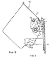
- the protective shield 46 can be brought into four different positions by being displaced and / or pivoted about the pivot bearing 50. These positions are referred to below as A, B, C and D, where A stands for a normal position in which the upper part 70 forms an angle of approximately 90 ° to the part of the rear side 16 lying above it, and that in FIG. 2 is reproduced. B denotes a position in which the upper part 70 encloses an angle of approximately 45 ° with the part of the rear side 16 lying above it and in which one already there is sufficient access to the universal joint shaft coupling (see Fig. 3).
- the cardan shaft coupling can already be dismantled in the inoperative state.
- the protective shield 46 is in its position C shown in FIG. 4, the upper part 70 forms an angle of approximately 105 ° with the part of the rear side 16 lying above it. In this position, a cardan shaft with a small cardan shaft coupling can optionally be connected, and at the same time a drawbar can be attached to the receiving device 20 in the lowest possible position.
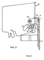
- the position D corresponding to FIG. 5, leads to the upper part 70 running parallel to the rear side 16 in order to achieve optimum access to the drive shaft coupling and to gain freedom of movement for mounting the stops 30 to limit the side play of the lower links 28. If the protective shield is in positions A or C, it can also be used as a step for the driver.
- the protective shield 46 In order to move the protective shield 46 from its normal position A to its position B, it is first pulled backwards to bring the short incision 98 out of engagement with the pin 52, and then upwards around the pivot bearing 50, i. H. 2 pivoted clockwise so far that the second recess 84 can be brought into engagement with the upper holder 44 and then be lowered onto it.
- the protective shield 46 is supported by the pawl 48 on the washer 78, which prevents it from sliding down and the pivot bearing 50 from reaching the sections 104, 106.
- the spacer sleeve 79 lies against the contours of the slot 72 in the section 102 during the entire process, and the pawl 48 slides with the long nose 113 on the disk 78.
- the protective shield 46 If the protective shield 46 is to assume its position C or D starting from the position A or B, then it must be pulled back until the pawl 48 releases the disk 78 so far that it rotates upward about the screw 80 in the counterclockwise direction can be pivoted away by hand with reference to the drawing, the short incision 98 simultaneously releasing the locking pin 52.
- the protective shield 46 can be moved from its position A or B to its position C by it is pivoted in Fig. 2 clockwise around the pivot bearing 50. It is then lowered and pivoted counterclockwise so that the front edge 92 can slide along the locking pin 52 until it enters the long incision 100. Simultaneously with this pivoting, the protective shield 46 slides down so far that the pivot bearing 50 passes the section 104 and comes to rest in the section 106.
- the long incision 100 lies on a circular arc around the center of the pivot bearing 50, so that the protective shield can be swiveled in the counterclockwise direction in the area of the long incision 100 into engagement with the locking pin 52 and brought to bear against it due to gravity.
- the pawl 48 has no function in this position.
- the protective shield 46 is moved from its position C into its position D by simply pivoting it clockwise in the clockwise direction with a view of the drawing upward about the pivot bearing 50, the locking pin 52 being disengaged from the long incision 100.
- the pivoting movement continues until the first recess 82 engages around the upper holder 44 and the protective shield 46 can be lowered onto it.
- the section 106 engages around the spacer sleeve 79 as previously described, so that the protective shield 46 is then held against pivoting by the holder 44 and by the bearing of the pivot bearing 50 in the section 106.
- the pawl 48 remains ineffective.
- the individual method steps have to be carried out in the reverse order.
- the protective shield 46 can be moved from any of the aforementioned positions A to D to any other position A to D without having to adhere to a specific sequence, with only the pawl 48 possibly having to be pivoted away or pivoted back.
- the straight section 112 is so close to the back 16 that neither larger objects between the top 70 and the back 16 can fall on the stub 34, nor that a person with his hand through the resulting Gap can reach the stub 34.
- the previously described embodiment of the protective device 22 can also be modified in such a way that the first recess 84 is omitted and the protective shield engages under the upper holder 44 by means of its straight section 112 and thus holds it in position B.
Abstract
Eine Schutzeinrichtung (22) zum Verhindern der Berührung mindestens eines sich drehenden Teiles (24), insbesondere einer Zapfwelle eines Ackerschleppers, weist ein Schutzschild (46) mit wenigstens einer Führung (72) auf, die derart mit einem ortsfesten Lager (50) zusammenwirkt, dass die Schutzeinrichtung (22) in mindestens eine Montagestellung und in zwei Schutzstellungen bringbar ist. Die Führung (72) besteht aus zwei Abschnitten (102, 104), wobei der Weg, den das Lager (50) in bezug auf die Führung (72) in dieser zurücklegen kann, mittels einer Sperre (48) derart geregelt wird, dass sich zum Erreichen der einen Schutzstellung das Lager (50) nur in dem einen Abschnitt (102) und zum Einnehmen der weiteren Schutzstellung das Lager (50) in beiden Abschnitten (102, 104) bewegen kann. In den jeweiligen Stellungen wird die Schutzeinrichtung (22) durch entsprechende Halterungen (52, 98, 100) gehalten.A protective device (22) for preventing contact with at least one rotating part (24), in particular a PTO shaft of an agricultural tractor, has a protective shield (46) with at least one guide (72), which cooperates with a fixed bearing (50) in this way, that the protective device (22) can be brought into at least one mounting position and two protective positions. The guide (72) consists of two sections (102, 104), the path which the bearing (50) can travel in relation to the guide (72) therein being regulated by means of a lock (48) in such a way that to reach the one protective position, the bearing (50) can only move in one section (102) and to take the further protective position the bearing (50) can move in both sections (102, 104). The protective device (22) is held in the respective positions by means of corresponding holders (52, 98, 100).
Description
Die Erfindung betrifft eine Schutzeinrichtung zum Verhindern der Berührung mindestens eines sich drehenden Teiles, insbesondere Schutzschild zum Abdecken einer Zapfwelle eines Ackerschleppers, die aus einer Schutzstellung, in der sie den sich drehenden Teil von mindestens einer Seite abdeckt, in eine Montagestellung, in der sie den Zugriff zu dem sich drehenden Teil ermöglicht, verstellbar, mit den einzelnen Stellungen zugeordneten Halterungen in Eingriff bringbar ist und zum Verstellen zwischen den beiden Stellungen wenigstens ein in einer Führung geführtes Lager aufweist, wobei die Führung oder das Lager an der Schutzeinrichtung und das Lager oder die Führung ortsfest angeordnet sind.The invention relates to a protective device for preventing contact with at least one rotating part, in particular a protective shield for covering a PTO of an agricultural tractor, which extends from a protective position, in which it covers the rotating part from at least one side, into an assembly position in which it Access to the rotating part is made possible, adjustable, can be brought into engagement with the holders assigned to the individual positions, and has at least one bearing guided in a guide for adjusting between the two positions, the guide or the bearing on the protective device and the bearing or the Guide are arranged stationary.
Aus Sicherheitsgründen wird beispielsweise in der Bundesrepublik Deutschland, aber auch in anderen Ländern, von staatlichen Institutionen, wie etwa der Berufsgenossenschaft, verlangt, daß angetriebene sich drehende Teile abgedeckt werden müssen, um Unfälle zu vermeiden, da sich an diesen sehr leicht Kleidungsstücke von Bedienungspersonen verfangen können. Gleichzeitig ist auch zu verhindern, daß diese Teile während ihres Einsatzes angefaßt werden können. Hierzu sind Sicherheitsvorschriften und Normen, wie etwa die DIN-Norm 31001 und die ISO-Norm 500,erlassen worden.For safety reasons, for example in the Federal Republic of Germany, but also in other countries, government institutions, such as the employers' liability insurance association, are required to cover rotating rotating parts to avoid accidents, since items of clothing can easily get caught on them by operators can. At the same time, it must also be prevented that these parts can be touched during their use. For this purpose, safety regulations and standards, such as the DIN standard 31001 and the ISO standard 500, have been issued.
In der Landtechnik wie aber auch in anderen Bereichen der Technik dienen die sich drehenden Teile meist zum Abnehmen von Antriebsmomenten, weshalb sie hierzu mit zu weiteren Maschinen führenden Anschlußstücken verbunden werden.In agricultural engineering as well as in other areas of technology, the rotating parts are mostly used to decrease drive torque, which is why they are connected to connectors leading to other machines.
So ist es bei Ackerschleppern üblich, diese mit einer sogenannten Zapfwelle auszurüsten, die von einem Verbrennungsmotor angetrieben wird und zumeist heckseitig aus einem Getriebegehäuse des Ackerschleppers austritt. Sie ist an ihrem aus dem Getriebegehäuse austretenden Ende mit einem Vielzahnprofil versehen, das der formschlüssigen Aufnahme einer Gelenkwellenkupplung einer zu einem angebauten oder angehängten Gerät führenden Gelenkwelle dient und in dem sich leicht Kleidungsstücke o. ä. verfangen können. Da die meisten Arbeitsgeräte am Heck des Ackerschleppers angebracht werden, befinden sich im Bereich der Zapfwelle gewöhnlich auch noch andere Aggregate wie eine Anhängerkupplung, eine Dreipunktgerätekupplung mit einem oberen und zwei unteren Lenkern und Anschläge zum Begrenzen der Seitenbeweglichkeit der unteren Lenker.So it is common with agricultural tractors to equip them with a so-called PTO shaft, which is driven by an internal combustion engine and usually exits from the rear of a transmission housing of the agricultural tractor. She is at hers end emerging from the gearbox housing is provided with a multi-tooth profile, which is used for the positive reception of an articulated shaft coupling of an articulated shaft leading to an attached or attached device and in which items of clothing or the like can easily get caught. Since most of the implements are attached to the rear of the tractor, there are usually other units in the area of the PTO, such as a trailer coupling, a three-point coupling with one upper and two lower links and stops to limit the lateral movement of the lower links.
Es ist somit zusätzlich zum Erfüllen der sicherheitstechnischen Vorschriften darauf zu achten, daß der Zugang zu den vorgenannten Aggregaten und deren Funktion gewahrt bleibt und nicht von der Schutzeinrichtung beeinträchtigt wird. Weiterhin ist aber noch zu beachten, daß die Schutzeinrichtung eine Montage und eine Demontage der Anschlußstücke, also der Gelenkwellenkupplung, zuläßt, so daß der Antrieb zu dem angehängten oder angebauten Gerät unterbrochen bzw. hergestellt werden kann.In addition to fulfilling the safety regulations, care must therefore be taken to ensure that access to the aforementioned units and their functions is maintained and is not impaired by the protective device. Furthermore, it should also be noted that the protective device permits assembly and disassembly of the connecting pieces, that is to say the cardan shaft coupling, so that the drive to the attached or attached device can be interrupted or manufactured.
So kann die Schutzeinrichtung (GB-PS 1 490 480), von der die Erfindung ausgeht, bereits in eine Schutzstellung, eine Montagestellung und in eine zwischen beiden Stellungen liegende Mittenstellung verstellt werden, wobei die Mittenstellung die Verwendung einer Gelenkwelle mit einem übermäßig großen Gelenkwellenkupplungsschutz ermöglicht.Thus, the protective device (GB-PS 1 490 480), from which the invention is based, can already be adjusted into a protective position, an assembly position and a central position between the two positions, the central position making it possible to use a cardan shaft with an excessively large cardan shaft coupling protection .
Sie weist hierzu ein Schutzschild mit zwei Seitenwänden und einen diese verbindenden Deckel und ortsfeste Lager auf, die mit in den Seitenwänden vorgesehenen Führungen in Form von Schlitzen derart zusammenwirken, daß das Schutzschild um die Lager herum in die verschiedenen Stellungen geschwenkt werden kann. Befindet sich das Schutzschild in einer seiner Stellungen, dann kann es mittels in den Seitenwänden vorgesehenen Rasten in Eingriff mit ebenfalls ortsfesten Arretierstiften gebracht und somit festgehalten werden.For this purpose, it has a protective shield with two side walls and a cover connecting these and stationary bearings which cooperate with guides provided in the side walls in the form of slots in such a way that the protective shield can be pivoted around the bearings into the different positions. If the protective shield is in one of its positions, it can be placed in the side walls seen notches brought into engagement with also fixed locking pins and thus held.
Diese Schutzeinrichtung erfüllt bereits alle Forderungen der Berufsgenossenschaft und hat sich in der Praxis gut bewährt.This protective device already fulfills all requirements of the professional association and has proven itself in practice.
Im Zuge stets umfangreicher werdender Ausrüstungen von Ackerschleppern mit den zuvor genannten Aggregaten wird es jedoch erforderlich, Schutzeinrichtungen zu verwenden, die beispielsweise auch die Verwendung einer höhenverstellbaren Anhängerkupplung zum Anpassen der jeweiligen Deichselhöhen an den Ackerschlepper zulassen. So könnte die Verwendung bestimmter höhenverstellbarer Anhängerkupplungen zunächst eine Demontage der bekannten Schutzeinrichtung für die Dauer, in der sich die Anhängerkupplung in ihrer tiefsten in den Bereich der Schutzeinrichtung eindringenden Stellung befindet, voraussetzen, wodurch sie allerdings keine schützende Wirkung mehr entfalten könnte.In the course of ever-increasing equipment of agricultural tractors with the aforementioned units, however, it becomes necessary to use protective devices which, for example, also allow the use of a height-adjustable trailer coupling to adapt the respective drawbar heights to the agricultural tractors. For example, the use of certain height-adjustable towbars could initially require disassembly of the known protective device for the duration in which the towbar is in its deepest position penetrating into the area of the protective device, which, however, could no longer have a protective effect.
Die der Erfindung zugrunde liegende Aufgabe wird darin gesehen, eine derartige Schutzeinrichtung so auszubilden, daß sie eine weitere untere Schutzstellung einnehmen kann.The object underlying the invention is seen in designing such a protective device in such a way that it can assume a further lower protective position.
Diese Aufgabe ist erfindungsgemäß dadurch gelöst worden, daß die Führung derart verlängert ist, daß die Schutzeinrichtung in eine weitere Schutzstellung verstellbar ist, und daß eine Sperre, gegen die das Lager in einer Schutzstellung zur Anlage bringbar ist, vorgesehen und derart ausgebildet ist, daß das Lager wahlweise in der gesamten Führung bewegt werden kann.This object has been achieved in that the guide is extended such that the protective device is adjustable in a further protective position, and that a lock against which the bearing can be brought into contact in a protective position is provided and designed such that the Bearing can optionally be moved throughout the guide.
Auf diese Weise kann die Schutzeinrichtung einmal eine Schutzstellung einnehmen, in der die sie umgebenden Aggregate innerhalb ihres für normale Arbeiten ausreichenden Bewegungsbereiches verstellt werden können und in der ein ungehinderter Betrieb der Zapfwelle mit der Gelenkwelle möglich ist. Sie kann zusätzlich in die weitere Schutzstellung verfahren werden, wenn eine höhenverstellbare Anhängerkupplung oder ein besonders tief abgesenkter oberer Lenker der Dreipunktgerätekupplung dies erfordern, wobei hingenommen wird, daß in der weiteren Schutzstellung ein Betrieb der Zapfwelle mit der Gelenkwelle nur bedingt möglich ist, aber dafür gesorgt ist, daß eine Bedienungsperson nur sehr schwer an eine ungewollt in Drehung versetzte Zapfwelle gelangt. Indem die Sperre an dem Lager zur Anlage bringbar ist, stützt sich die Schutzeinrichtung auf dem Lager ab und kann durch auf sie herabfallende Erdschollen oder ähnliches nicht in die weitere Schutzstellung gebracht, aber als Auftritt zur Hilfe beim Aufsteigen auf den Ackerschlepper benutzt werden. Durch die verlängerte Führung erfährt die Schutzeinrichtung wahlweise, d. h. wenn die Sperre entfernt worden ist, einen größeren Bewegungsbereich und kann so zum Verstellen nach hinten außer Eingriff mit den Halterungen gezogen, um das Lager geschwenkt, abgesenkt und in Eingriff mit der Halterung für die weitere Schutzstellung gebracht werden, ohne daß die Schutzeinrichtung von dem Lager abgenommen werden müßte. Selbstverständlich sind die Bewegungen zwischen den jeweils zusammengehörenden Lagern und Führungen Relativbewegungen, weshalb es belanglos ist, ob das Lager oder die Führung feststehen und die Füh- rung oder das Lager bewegt werden.In this way, the protective device can once occupy a protective position in which the aggregates surrounding it can be adjusted within their range of motion sufficient for normal work and in which an un hindered operation of the PTO with the PTO shaft is possible. It can also be moved into the further protection position if a height-adjustable trailer coupling or a particularly low-lowered upper link of the three-point implement coupling require this, whereby it is accepted that in the further protection position an operation of the PTO shaft with the PTO shaft is only possible to a limited extent, but is ensured is that it is very difficult for an operator to reach an unintentionally rotated PTO. Since the lock on the bearing can be brought into contact with the system, the protective device is supported on the bearing and cannot be brought into the further protective position by earth clods or the like falling on it, but can be used as an aid to ascending the tractor. Due to the extended guide, the protective device optionally experiences a larger range of motion, ie when the lock has been removed, and can be pulled out of engagement with the brackets for adjustment to the rear, pivoted around the bearing, lowered and in engagement with the bracket for the further protective position brought without having to remove the protective device from the camp. Of course, the movements between the respective mating bearings and guides relative movements, and it is therefore irrelevant whether the bearing or the guide are fixed and the F üh- tion or the bearing to be moved.
Der Erfindung entsprechend wird auf besonders einfache Weise die Verstellung der Schutzeinrichtung dadurch ermöglicht, daß die Führung als Schlitz mit mindestens zwei in etwa rechtwinklig zueinander verlaufenden Abschnitten ausgebildet ist, wobei der erste Abschnitt waagerecht oder in einem geringen Winkel zu der Waagerechten in der einen Schutzstellung und der zweite Abschnitt als hochstehender Schenkel in der weiteren Schutzstellung angeordnet ist.According to the invention, the adjustment of the protective device is made possible in a particularly simple manner in that the guide is designed as a slot with at least two sections running approximately at right angles to one another, the first section being horizontal or at a slight angle to the horizontal in one protective position and the second section is arranged as an upstanding leg in the further protective position.
Die Schutzeinrichtung kann demnach in zwei Richtungen um das Lager verfahren werden, wobei davon ausgegangen wird, daß die Waagerechte die Aufstandsebene des relativ ortsfesten Teiles, insbesondere des Ackerschleppers, ist. Der rechtwinklig zu dem ersten Abschnitt verlaufende zweite Abschnitt würde bei einem Ackerschlepper parallel zu der Heckseite des Getriebegehäuses verlaufen, und die Schutzeinrichtung könnte an diesem entlang nach unten in die weitere Schutzstellung gebracht werden.The protective device can therefore be moved in two directions around the camp, it being assumed that the horizontal is the contact plane of the relatively stationary part, in particular the agricultural tractor. The second section running at right angles to the first section would run parallel to the rear side of the transmission housing in the case of an agricultural tractor, and the protective device could be moved along this downward into the further protective position.
Um zu vermeiden, daß das Lager ungewollt aus der dem ersten Abschnitt zugeordneten Schutzstellung in die dem zweiten Abschnitt zugeordnete weitere Schutzstellung gelangt, ist des weiteren erfindungsgemäß vorgesehen, daß das Lager in dem Übergang von dem einen Abschnitt zu dem anderen Abschnitt wahlweise gegen die Sperre zur Anlage bringbar ist, wobei die Sperre in den Bewegungsbereich des Lagers schwenkbar und an einem die Führung aufweisenden Teil angelenkt ist. Die Bewegung der Schutzeinrichtung wird demgemäß einfach dadurch gesteuert, daß die Sperre von der Bedienungsperson in oder aus dem Bewegungsbereich des Lagers geschwenkt wird.In order to avoid that the bearing unintentionally gets from the protective position assigned to the first section into the further protective position assigned to the second section, it is further provided according to the invention that the bearing in the transition from one section to the other section selectively against the lock System can be brought, the lock being pivotable in the range of motion of the bearing and articulated to a part having the guide. The movement of the protective device is accordingly controlled simply by the operator pivoting the lock into or out of the movement range of the bearing.
In vorteilhafter Ausgestaltung ist nach einem zusätzlichen erfindungsgemäßen Vorschlag vorgesehen, daß die Sperre eine schwenkbare Klinke ist und daß die Klinke eine der Außenkontur des Lagers angepaßte Aussparung aufweist. Die Klinke kann manuell von dem Lager weggeschwenkt werden, wenn die Schutzeinrichtung in die weitere Schutzstellung gebracht werden soll, oder an dem Lager zur Anlage gebracht werden, wenn die Schutzeinrichtung die Schutzstellung einnehmen soll, wobei die Klinke auf das Lager einfach abgelassen werden kann und dort aufgrund ihrer Aussparung einen sicheren Halt erfährt.In an advantageous embodiment, it is provided according to an additional proposal according to the invention that the lock is a pivotable pawl and that the pawl has a recess which is adapted to the outer contour of the bearing. The pawl can be manually pivoted away from the bearing when the protective device is to be brought into the further protective position, or brought to bear against the bearing when the protective device is to assume the protective position, the latch can simply be lowered onto the bearing and there due to its recess is securely held.
Dadurch, daß erfindungsgemäß sich an den zweiten Abschnitt ein dritter Abschnitt anschließt, der eine seitliche Aussparung aufweist, in der das Lager zur Anlage gebracht werden kann, ist es möglich, die Schutzeinrichtung in einer weiteren Stellung, die keine Schutzstellung sein muß, sondern in der die Montage oder Demontage einer Gelenkwellenkupplung auf oder von der Zapfwelle des Ackerschleppers möglich ist, zu halten. Die formschlüssige Verbindung des Lagers mit der Aussparung sorgt dafür, daß die Schutzeinrichtung nicht ungewollt in eine der Schutzstellungen zurückfällt.Characterized in that, according to the invention, the third section is followed by a third section which has a lateral recess in which the bearing can be brought into contact, it is possible to position the protective device in a further position, which does not have to be a protective position, but in the the assembly or disassembly of an articulated shaft coupling on or from the PTO of the tractor is possible. The positive connection of the bearing with the recess ensures that the protective device does not fall back into one of the protective positions unintentionally.
Eine Schutzeinrichtung, bei der die Halterungen aus jeweils einem ortsfesten Arretierstift und mindestens zwei in dem schwenkbaren Teil vorgesehenen Einschnitten bestehen, die Führung und das in ihr aufgenommene Lager mit seitlichem Abstand zu dem Schwerpunkt des sie aufnehmenden Teiles angeordnet und das Lager in der Führung frei drehbar ist, ist gemäß der Erfindung vorzugsweise derart ausgebildet, daß die verlängerte Führung derart angeordnet ist, daß der der weiteren Schutzstellung zugeordnete Einschnitt auf einem Kreisbogen um das Lager gelegen ist, wenn die Schutzeinrichtung die weitere Schutzstellung einnimmt, und länger ist als der der Schutzstellung zugehörige Einschnitt.A protective device in which the brackets each consist of a fixed locking pin and at least two incisions provided in the pivotable part, the guide and the bearing accommodated therein are arranged at a lateral distance from the center of gravity of the part receiving it and the bearing is freely rotatable in the guide is preferably designed according to the invention such that the elongated guide is arranged such that the incision associated with the further protective position is located on an arc around the bearing when the protective device assumes the further protective position, and is longer than that associated with the protective position Incision.
Eine derartige Ausführung gewährleistet, daß selbst bei heftigsten auf die Schutzeinrichtung einwirkenden Erschütterungen, die ein Verschwenken der Schutzeinrichtung herbeiführen, diese aufgrund der Schwerkraft wieder in ihre Schutzstellung zurückschwenkt. Durch die gegenüber dem Einschnitt für die Schutzstellung größere Länge des Einschnittes schwenkt das Schutzschild so weit nach unten, bis der Arretierstift an dem Ende des Einschnittes zur Anlage kommt. Durch das tiefe Absinken des Schutzschildes wird mehr Freiraum für die höhenverstellbare Anhängerkupplung und den oberen Lenker gewonnen.Such a design ensures that even with the most violent vibrations acting on the protective device, which cause the protective device to pivot, it swings back into its protective position due to gravity. Due to the greater length of the incision compared to the incision for the protective position, the protective shield pivots downwards until the locking pin comes into contact with the end of the incision. The lowering of the protective shield creates more space for the height-adjustable trailer hitch and the upper handlebar.
Den Sicherheitsvorschriften Rechnung tragend ist nach der Erfindung eine Schutzeinrichtung mit sich an den Mündungen der Einschnitte ergebenden Kanten derart ausgebildet, daß eine sich an der Mündung des der Schutzstellung zugehörigen Einschnittes ergebende, dem Lager zugelegene Kante weiter von dem Lagermittelpunkt entfernt ist als mindestens eine von ebenfalls dem Lager zugelegenen Kanten des Arretierstiftes, wenn die Schutzeinrichtung ihre Schutzstellung einnimmt. Diese Merkmale bewirken, daß beim Einwirken von Erschütterungen auf das Schutzschild dieses nicht um das Lager schwenken kann, sondern mit der Kante des der Schutzstellung zugehörigen Einschnittes an dem Arretierstift zur Anlage gerät und seine Schutzstellung auch unter diesen widrigen Umständen beibehält.Taking the safety regulations into account, according to the invention a protective device is formed with edges resulting at the mouths of the incisions such that an edge resulting at the mouth of the incision belonging to the protective position and located at the bearing is further away from the center of the bearing than at least one of the same edges of the locking pin facing the bearing when the protective device is in its protective position. These features mean that when the protective shield is subjected to vibrations, it cannot pivot around the bearing, but comes to rest with the edge of the cut associated with the protective position on the locking pin and maintains its protective position even under these adverse circumstances.
Um die Schutzeinrichtung in ihrer Montagestellung zu halten, ist erfindungsgemäß ein Halter vorgesehen, der mit mindestens einer in einem Oberteil des Schutzschildes angeordneten Aussparung in Formschluß bringbar ist, wenn die Schutzeinrichtung ihre Montagestellung einnimmt, wobei mit mehreren in dem Oberteil vorgesehenen Aussparungen das Schutzschild während der Montage oder Demontage einer Gelenkwellenkupplung in verschiedenen den jeweiligen Platzerfordernissen Rechnung tragenden Stellungen festgelegt werden kann.In order to keep the protective device in its mounting position, a holder is provided according to the invention, which can be brought into positive engagement with at least one recess arranged in an upper part of the protective shield when the protective device assumes its mounting position, the protective shield being provided with several recesses in the upper part during the Assembly or disassembly of a cardan shaft coupling can be determined in various positions that take into account the respective space requirements.
Ein unbeabsichtigtes Freigeben des Überganges von dem ersten zu dem zweiten Abschnitt durch ein von Erschütterungen verursachtes Schwenken der Klinke wird dadurch erschwert, daß seitlich der Aussparung der Klinke eine kurze und eine lange Nase angeordnet sind, wobei die lange Nase beim Aufliegen der Klinke auf dem Lager oberhalb von diesem zu liegen kommt, da selbst dann, wenn sich die Führung mit dem Schutzschild über die gesamte Länge des Abschnittes verschiebt und sich die Klinke von dem Lager wegbewegt, die Klinke mit der langen Nase nicht an dem Lager vorbei nach unten, sondern nur entgegen der Schwerkraft nach oben schwenken kann.An unintentional release of the transition from the first to the second section by a pivoting of the pawl caused by vibrations is made more difficult by the fact that a short and a long nose are arranged to the side of the recess of the pawl, the long nose when the pawl rests on the bearing comes to lie above this, because even if the guide with the protective shield moves over the entire length of the section and the pawl moves away from the bearing, the pawl with the long nose does not pass the bearing downwards, but only can swing upward against gravity.
Solange sich die Schutzeinrichtung in ihrer Schutzstellung befindet, umgreift die Klinke mit der kurzen und der langen Nase das Lager derart, daß sie weder nach oben noch nach unten schwenken kann.As long as the protective device is in its protective position, the pawl with the short and long nose engages around the bearing in such a way that it can neither pivot up nor down.
Ein nachfolgend näher beschriebenes Ausführungsbeispiel der Erfindung ist in der Zeichnung dargestellt. Es zeigt:
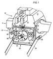
- Fig. 1 eine Ansicht einer Heckseite eines Ackerschleppers mit einer erfindungsgemäßen Schutzeinrichtung,
- Fig. 2 ein Schutzschild der Schutzeinrichtung im angebauten Zustand in einer Normalposition in Seitenansicht,
- Fig. 3 das Schutzschild in einer zweiten Position in Seitenansicht,
- Fig. 4 das Schutzschild in einer dritten Position in Seitenansicht,
- Fig. 5 das Schutzschild in einer vierten Position in Seitenansicht.
- 1 is a view of a rear side of an agricultural tractor with a protective device according to the invention,
- 2 a protective shield of the protective device in the mounted state in a normal position in a side view,
- 3 the protective shield in a second position in a side view,
- 4 the protective shield in a third position in side view,
- Fig. 5 shows the protective shield in a fourth position in a side view.
Ein in Fig. 1 teilweise dargestelltes Heck 10 eines Ackerschleppers wird im wesentlichen von einem Getriebegehäuse 12 gebildet, an das auf jeder Seite ein Achstrichter 14 angeflanscht ist und an dessen Rückseite 16 ein Halter 18 zum Aufnehmen eines nicht gezeigten oberen Lenkers, eine Aufnahmevorrichtung 20 eines in der Zeichnung weggelassenen höhenverstellbaren Zugmauls und eine Schutzeinrichtung 22 für einen sich drehenden Teil in Form einer Zapfwelle 24 angebaut sind. Ferner ragt rückwärtig und unterhalb der Achstrichter 14 ein Biegestab 26 aus dem Getriebegehäuse 12 heraus, der beidseitig des Getriebegehäuses 12 jeweils einen unteren Lenker 28 schwenkbar aufnimmt. Zwischen dem unteren Lenker 28 und dem Getriebegehäuse 12 ist ein Anschlag 30 zum Begrenzen des Seitenspiels der unteren Lenker 28 vorgesehen, und unterhalb am rückwärtigen Ende des Getriebegehäuses 12 befindet sich eine Halterung 32 für ein der Einfachheit wegen in der Zeichnung weggelassenes Zugpendel.A rear 10 of a tractor, partially shown in FIG. 1, is essentially formed by a
Die Zapfwelle 24 wird über nicht ersichtliche Antriebsmittel, die in dem Getriebegehäuse 12 angeordnet sind, und abhängig von der Stellung einer Steuervorrichtung von einem Antriebsmotor aus, die beide nicht gezeigt sind, angetrieben, d. h. in Drehung versetzt. Von der Zapfwelle 24 ragt lediglich ein Stummel 34 aus der Rückseite 16 des Getriebegehäuses 12 heraus, der in einem Lagerteil 36 drehbar aufgenommen ist und an seinem Umfang Verzahnungen 38 aufweist, die mit einer nicht dargestellten Gelenkwellenkupplung formschlüssig in Eingriff gebracht werden können. Eine mit letzterer verbundene Gelenkwelle führt gewöhnlich zu einem antreibbaren Arbeitsgerät, etwa in Form eines Düngerstreuers, einer Bodenfräse, einer Erntemaschine oder ähnlichem,oder zu einem Anhänger, der an das Zugmaul angehängt ist und dessen Räder oder dessen Aufbau über die Gelenkwelle in Bewegung versetzt werden.The power take-
Um zu vermeiden, daß durch die sich im Betrieb drehende Gelenkwelle Unfälle verursacht werden können, sind sämtliche sich in Drehung befindliche Teile abzudecken, was bei der Gelenkwelle durch deren Einsetzen in ein lose mit ihr verbundenes Schutzrohr geschieht, während für den aus dem Getriebegehäuse 12 herausragenden Stummel 34 die erfindungsgemäße Schutzeinrichtung 22 vorgesehen ist.In order to avoid that accidents can be caused by the PTO shaft rotating during operation, all rotating parts must be covered, which is done with the PTO shaft by inserting it into a protective tube that is loosely connected to it, while protruding from the
Diese Schutzeinrichtung 22 soll derart ausgebildet sein, daß sie nicht nur den drehenden Stummel 34 der Zapfwelle 24 und die Gelenkwellenkupplung unfallsicher abdeckt, sondern auch die Bedienung und den Anbau weiterer Komponenten des Ackerschleppers wie das Zugmaul und das Zugpendel und die unteren und den oberen Lenker nicht behindert. Ferner soll sie im außerbetrieblichen Zustand einen freien Zugang zu der Gelenkwellenkupplung gewähren, um diese von dem Stummel 34 abziehen zu können. Eine weitere Forderung besagt, daß die Schutzeinrichtung 22 ohne Wartung stets betriebsbereit sein muß und daß zu ihrer Funktion keine Teile verwendet werden dürfen, die unter den Betriebsbedingungen eines Ackerschleppers infolge seiner Berührung mit Wasser, Sand, Schlamm u. v. a. eine Funktionslosigkeit der Schutzeinrichtung 22 hervorrufen könnten.This
Hierzu weist die Schutzeinrichtung 22 im wesentlichen einen linken, einen rechten und einen oberen Halter 40, 42, 44, ein Schutzschild 46 mit sich in Fahrtrichtung erstreckenden Außenseiten, an denen sich jeweils eine Sperre oder Klinke 48, ein als Schwenklager 50 wirkendes Lager und ein Arretierstift 52 befinden, auf, wobei sich die Angaben links und rechts auf die Vorwärtsfahrtrichtung des Ackerschleppers beziehen. Je nach den Abmessungen der Schutzeinrichtung 22, insbesondere im Hinblick auf die verwendeten Materialien und die ausgewählten Materialstärken, kann es auch bereits ausreichend sein, wenn die Klinke 48, das Schwenklager 50 und der Arretierstift 52 nur auf der einen Außenseite des Schutzschildes 46 vorgesehen sind.For this purpose, the
Der linke und der rechte Halter 40 und 42 sind spiegelbildlich ausgebildet und bestehen aus je einem Winkeleisen, dessen einer Schenkel 56 über Schrauben an die Rückseite 16 des Getriebegehäuses 12 angeflanscht ist, während der andere Schenkel 58 sich rückwärtig von dem Getriebegehäuse 12 fort erstreckt und an den eine eine in den Figuren nicht erkennbare Bohrung aufweisende Lasche 60, die sich ebenfalls rückwärtig erstreckt, angeschweißt ist. An dem unteren Ende des anderen Schenkels 58 ist schließlich der Arretierstift 52 angebracht, und zwar so, daß er von diesem sich quer zur Fahrtrichtung fort erstreckt. Der obere Halter 44 ist zweifach entgegengesetzt um 90° gekröpft und weist somit im wesentlichen ein Z-Profil auf, wobei ein nach unten gerichteter Schenkel 62 eine in Fig. 1 verdeckte Bohrung besitzt, durch die sich eine Schraube 64 zum Eindrehen in eine nicht erkennbare Gewindebohrung in der Rückseite 16 des Getriebegehäuses 12 erstreckt. Der obere Halter 44 ist mittig zwischen dem linken und dem rechten Halter 40, 42 und etwas oberhalb von diesen angeordnet.The left and right holders 40 and 42 are mirror images and each consist of an angle iron, one
Das Schutzschild 46 weist im wesentlichen eine U-Form mit einem linken und einem rechten Seitenteil 66, 68 sowie einem Oberteil 70 auf und ist nach unten, nach vorn und nach hinten geöffnet. Jeder Seitenteil 66, 68 ist mit einer als Schlitz 72 ausgebildeten Führung versehen, durch die sich eine Schraube 74 des Schwenklagers 50 bis durch die Bohrung in der Lasche 60 hindurch erstreckt und dort über eine Mutter 76 gehalten wird, wobei sich unter dem Kopf der Schraube 74 eine Scheibe 78 mit einem Durchmesser, der größer ist als die Breite des Schlitzes 72, befindet und sich zwischen der Scheibe 78 und der Lasche 60 eine Distanzhülse 79 erstreckt, deren Außendurchmesser geringfügig kleiner ist als die Breite des Schlitzes 72. Das rückwärtige Ende 61 der Lasche 60, in dem sich auch die Bohrung befindet, ist nierenförmig ausgebildet, und zwar derart, daß in jeder Stellung des Schutzschildes 46 der Schlitz 72 verdeckt ist und somit ein die Schutzeinrichtung 22 Bedienender mit seinen Fingern nicht in den von dem Schutzschild 46 umschlossenen Gefahrenbereich durch den Schlitz 72 gelangen kann. Das Schwenklager 50 kann auch dergestalt ausgebildet sein, daß die Distanzhülse 79 und die Scheibe 78 als ein einziger Teil mit T-förmigem Querschnitt und mit einer zentrischen Gewindebohrung ausgebildet sind, wobei der Fuß des T die Funktion der Distanzhülse 79 und der Kopf des T die Funktion der Scheibe 78 übernimmt und dieser Teil über eine gewöhnliche Schraube, die sich durch die Bohrung in der Lasche 60 nach außen erstreckt, an der Lasche 60 befestigt wird. Die Verwendung der Distanzhülse 79 ermöglicht es, die Schraube 74 so fest anzuziehen, daß sie nur unter Verwendung geeigneten Werkzeuges, jedoch nicht mit der bloßen Hand, wieder entfernt und somit der Schutz demontiert werden kann. Dies ist ein präventives Sicherheitsmerkmal, das einer Demontage des Schutzschildes 46 seitens des Bedienenden aus unwichtigen Beweggründen heraus vorbeugt. Rückwärtig des Schlitzes 72 ist die Klinke 48 angebracht, die von einer sich durch eine nicht ersichtliche Bohrung in dem Schutzschild 46 erstreckenden Schraube 80 gehalten wird, wobei sich zwischen dem Kopf der Schraube 80 und dem Schutzschild 46 wiederum eine nicht erkennbare Distanzhülse befindet. In den Oberteil 70 sind eine erste und eine zweite Aussparung 82, 84 mittig zwischen den beiden Seitenteilen 66, 68 eingebracht, die geeignet sind, einen oberen Schenkel 86 des oberen Halters 44 in sich aufzunehmen. Die Tiefe der ersten und der zweiten Aussparung 82 und 84 entspricht dabei mindestens der Höhe des oberen Schenkels 86 des oberen Halters 44. Zur weiteren Beschreibung insbesondere der Form der Seitenteile 66, 68 des Schutzschildes 46 wird im folgenden auf Fig. 2 verwiesen.The
Das Schutzschild 46 ist symmetrisch ausgestaltet, weshalb nachfolgend nur der rechte Seitenteil 68 beschrieben wird. Diese Beschreibung gilt für den linken Seitenteil 66 analog.The
Der rechte Seitenteil 68 weist eine obere, eine untere, eine vordere und eine rückwärtige Kante 88, 90, 92 und 94 auf, die eine ungefähr quadratische Fläche umschließen. Die vordere Kante 92 weist außer zwei Ausschnitten 96, die lediglich ein Anstoßen der Seitenteile 66, 68 an benachbarte Teile verhindern sollen, einen kurzen und einen langen Einschnitt 98 und 100 auf, die wahlweise in sich den Arretierstift 52 aufnehmen können und somit eine Halterung bilden. Beide Einschnitte 98, 100 sind in der unteren Hälfte des Seitenteils 68 angeordnet, wobei der lange Einschnitt 100 über dem kurzen 98 zu liegen kommt und die Form eines nach oben gewölbten Bogens aufweist, wie dies später noch erläutert wird. In der oberen Hälfte des Seitenteils 68 und etwas nach hinten gegenüber den Einschnitten 98, 100 versetzt ist der Schlitz 72 in den Seitenteil 68, der aus ca. 2 mm starkem Stahlblech besteht, eingefräst oder eingestanzt. Der Schlitz 72 selbst besteht aus drei Abschnitten, nämlich einem jeweils mit Bezug auf die Aufstandsebene des Ackerschleppers fast waagrechten, jedoch leicht nach hinten ansteigenden Abschnitt 102, einem nahezu senkrechten, jedoch oben leicht nach vorne kippenden Abschnitt 104 und einem waagrechten, in seiner Länge die Breite des Schlitzes 72 geringfügig übertreffenden Abschnitt 106. Die Breite des Schlitzes 72 in den Abschnitten 102, 104 und 106 ist identisch. Der Abschnitt 102 verläuft zu der Rückseite 16 in einem Winkel von ca. 65°, der Abschnitt 104 zu dem Abschnitt 102 in einem Winkel von ca. 90° und der Abschnitt 106 zu der Rückseite 16 in einem Winkel von ca. 90°. An der oberen Kante 88 des Seitenteils 68 schließt der Oberteil 70 an, wobei zur Erhöhung der Steifheit des Schutzschildes 46 an der oberen Kante 88 Sicken 108 vorgesehen sind. Der Oberteil 70 ist auf einer Länge von ungefähr 2/3 der Länge der oberen Kante 88 mit dem Seitenteil 68 verbunden und in sich eben. Auf der restlichen Länge, die sich von der vorderen Kante 90 bemißt, ist er nach vorne und nach unten leicht geneigt abgebogen, und in einer hierdurch entstandenen Schräge 110 ist die zweite Aussparung 84 gelegen. Die Schräge 110 läuft abschließend in ein gerades Teilstück 112 aus, das sich bis unterhalb des oberen Halters 44 erstreckt, wenn der Oberteil 70 mit seinem geraden Teilstück 112 senkrecht zu der Rückseite 16 des Getriebegehäuses 12 verläuft, wobei die Länge des geraden Teilstückes 112 so bemessen ist, daß es die nachfolgend beschriebene Schwenkbewegung des Schutzschildes 46 um das Schwenklager 50 nicht stört. Die erste Aussparung 82 befindet sich in dem geraden Teilstück des Oberteils 70, und zwar nahe und rückwärtig einer sich zwischen dem Oberteil 70 und der Schräge 110 ergebenden Kante 114.The
Die Klinke 48 weist eine Dreiecksgestalt auf und ist an ihrer der Bohrung gegenüberliegenden Seite mit einer halbrunden Aussparung 116 versehen, die in der zuvor beschriebenen Stellung die Scheibe 78 ungefähr zur Hälfte umgreift. Die Klinke selbst ist um 360° um die Schraube 80 schwenkbar. Die die Klinke 48 haltende Schraube 80 ist am oberen Ende und rückwärtig des Schlitzes 72 plaziert, so daß sich die Klinke 48 über ihre halbrunde Aussparung 116 auf der Scheibe 78 abstützt, solange der kürzeste Abstand des Umfangs der Scheibe 78 zu der Schraube 80 geringer ist als der Abstand der Schraube 80 zu der am weitesten entfernten Stelle der Klinke 48 auf einer der beiden Seiten der halbrunden Aussparung 116. Aufgrund der versetzten Anordnung der Klinke 48 gegenüber dem Schlitz 72 und somit dem Schwenklager 50 und der Anordnung der die Klinke 48 haltenden Schraube 80 in ihr ergibt sich, daß der Abstand von der den Schwenkpunkt bildenden Schraube 80 zu den der halbrunden Aussparung 116 nahe gelegenen Ecken des Dreiecks unterschiedlich groß ist. So ist eine die halbrunde Aussparung 116 einerseits begrenzende Nase 113 länger als eine dieser gegenüberliegende Nase 115, weshalb selbst beim Nachhintenziehen des Schutzschildes 46 die Klinke 48 mit ihrer kürzeren Nase 115 bereits an dem Schwenklager 50 vorbeigeschwenkt werden kann, während die Klinke 48 über ihre längere Nase 113 noch auf der Scheibe 78 aufliegt und somit nicht ungewollt außer Eingriff mit dem Schwenklager 50 kommen kann. Sobald jedoch das Schutzschild 46 so weit verschoben wird, daß die zuvor genannten Abstände zumindest gleich groß werden, kann die Klinke 48 in einer Richtung, und zwar nach oben, an der Scheibe 78 vorbeigeschwenkt werden. Hierzu ist dann das Schutzschild 46 seitlich mit den Händen anzufassen und die Klinke 48 beispielsweise mit dem Daumen nach oben wegzuschwenken. Es ist zu erkennen, daß durch die Form der Klinke 48 diese grundsätzlich nicht ohne Zutun eines Bedienenden an der Scheibe 78 vorbeigeschwenkt werden kann und so beim Fahren auf holprigen Wegstrecken die Klinke 48 ihre Stellung beibehält oder in diese zurückfällt, in der sie ein Eintreten des Schwenklagers 50 in den Abschnitt 104 verhindert. Die Länge des Schlitzes 72 in seinem Abschnitt 102, wobei die Länge als die jeweils größte Dimension dieses Abschnittes 102 wie auch der anderen Abschnitte 104, 106, ungeachtet der Lage des Schlitzes 72, angesehen wird, ist derart bemessen, daß sie mindestens eine Bewegung des Schutzschildes 46 zuläßt derart, daß die Klinke 48 an der Scheibe 78 nach oben vorbeigeschwenkt werden kann, d. h. eine Bewegung um das Differenzmaß der zuvor genannten Abstände und zusätzlich den Durchmesser der Distanzhülse 79, damit das Schutzschild 46 mit der oberen Kontur des Schlitzes 72 in seinem Abschnitt 102 auf der Distanzhülse 79 aufliegen kann. Das Schutzschild 46 kann lediglich begrenzt durch die Konturen des Schlitzes 72 um das Schwenklager 50 geschwenkt und an diesem vorbeigeschoben werden. Die Länge des Abschnittes 106 ist um die Höhe des oberen Schenkels 86 des oberen Halters 44 größer als die Breite des Schlitzes 72 in den Abschnitten 102 und 104, so daß dann, wenn sich das Schutzschild 46 in einer später noch zu beschreibenden Stellung befindet, es mit seiner ersten Aussparung 82 über den oberen Schenkel 86 auf den oberen Halter 44 aufgesetzt und vor dem oberen Schenkel 86 auf den oberen Halter abgelassen werden kann, wodurch die Distanzhülse 79 des Schwenklagers 50 durch die Anlage an dem Schutzschild 46 dieses im Abschnitt 106 gegen ein Verschwenken hält.The
Entsprechend dem Vorbeschriebenen kann das Schutzschild 46 in vier verschiedene Positionen gebracht werden, indem es um das Schwenklager 50 verschoben und/oder geschwenkt wird. Diese Positionen werden im folgenden mit A, B, C und D bezeichnet, wobei A für eine Normalposition steht, in der der Oberteil 70 zu dem über ihm liegenden Teil der Rückseite 16 einen Winkel von ca. 90° einschließt und die in Fig. 2 wiedergegeben ist. Mit B wird eine Position bezeichnet, in der der Oberteil 70 mit dem über ihm liegenden Teil der Rückseite 16 einen Winkel von ca. 45° einschließt und in der bereits eine ausreichend gute Zugänglichkeit zu der Gelenkwellenkupplung gegeben ist.(siehe hierzu Fig. 3). In Position B kann bei sich senkrecht zu der Rückseite 16 erstreckender Gelenkwelle im betriebslosen Zustand die Gelenkwellenkupplung bereits demontiert werden. Befindet sich das Schutzschild 46 in seiner in Fig. 4 dargestellten Position C, dann schließt der Oberteil 70 mit dem über ihm liegenden Teil der Rückseite 16 einen Winkel von ca. 105° ein. In dieser Position kann gegebenenfalls noch eine Gelenkwelle mit einer kleinen Gelenkwellenkupplung angeschlossen sein, und gleichzeitig kann ein Zugmaul an der Aufnahmevorrichtung 20 in der tiefstmöglichen Stellung angebracht werden. Die Position D, entsprechend Fig. 5, führt zu einem parallelen Verlaufen des Oberteils 70 zu der Rückseite 16, um einen optimalen Zugriff zu der Gelenkwellenkupplung zu erreichen und um Bewegungsfreiheit zum Anbau der Anschläge 30 zum Begrenzen des Seitenspiels der unteren Lenker 28 zu gewinnen. Befindet sich das Schutzschild in seinen Positionen A oder C, dann kann es auch als Trittstufe für den Fahrer genutzt werden.In accordance with what has been described above, the
In der Normalposition A liegt der Arretierstift 52 in dem kurzen Einschnitt 98 an, und das Schwenklager 50 befindet sich in dem Abschnitt 102 des Schlitzes 72. Die Klinke 48 liegt an der Scheibe 78 an, und der obere Halter 44 ist mit keiner der Aussparungen 82, 84 in Eingriff. Die Distanzhülse 79 liegt an der oberen Kontur des Schlitzes 72 in dem Abschnitt 102 an und verhindert gemeinsam mit dem Arretierstift 52, daß das Schutzschild 46 hinten nach unten aufgrund der Schwerkraft wegschwenkt. Eine Schwenkbewegung des Schutzschildes 46 im Uhrzeigerdrehsinn mit Blickrichtung auf Fig. 2 wird insbesondere dadurch verhindert, daß der kurze Einschnitt 98 den Arretierstift 52 nicht freigibt, solange das Schutzschild 46 nicht nach hinten gezogen worden ist. Eine reine Schwenkbewegung in der Stellung A im Uhrzeigerdrehsinn, wie sie sich beispielsweise beim Fahren auf einer holprigen Strecke von selbst ergeben könnte, ist also nicht möglich. Selbst bei einer Verschiebung des Schutzschildes 46 aufgrund von stärksten Erschütterungen so weit, daß der kurze Einschnitt 98 momentan außer Eingriff mit dem Arretierstift 52 gelangen sollte, würde das Schutzschild 46 aufgrund der Schwerkraft wieder nach unten fallen und entweder an der vorderen Kante 92 anliegen oder zurück in den kurzen Einschnitt 98 eintreten.In normal position A, the locking
Um das Schutzschild 46 aus seiner Normalposition A in seine Position B zu bringen, wird es zunächst nach hinten gezogen, um den kurzen Einschnitt 98 außer Eingriff mit dem Stift 52 zu bringen, und dann um das Schwenklager 50 hinten nach oben, d. h. in Fig. 2 im Uhrzeigerdrehsinn, verschwenkt, und zwar so weit, daß die zweite Aussparung 84 mit dem oberen Halter 44 in Eingriff gebracht und dann auf diesen abgelassen werden kann. Während des Verschwenkens stützt sich das Schutzschild 46 über die Klinke 48 auf der Unterlegscheibe 78 ab, wodurch verhindert wird, daß es nach unten rutscht und das Schwenklager 50 in die Abschnitte 104, 106 gelangt. Die Distanzhülse 79 liegt während des ganzen Vorganges an den Konturen des Schlitzes 72 in dem Abschnitt 102 an, und die Klinke 48 gleitet mit der langen Nase 113 auf der Scheibe 78.In order to move the
Soll das Schutzschild 46 ausgehend von der Position A oder B seine Position C oder D einnehmen, dann ist es so weit nach hinten zu ziehen, bis die Klinke 48 die Scheibe 78 so weit freigibt, daß sie um die Schraube 80 entgegen dem Uhrzeigerdrehsinn nach oben mit Bezug auf die Zeichnung von Hand fortgeschwenkt werden kann, wobei der kurze Einschnitt 98 gleichzeitig den Arretierstift 52 freigibt.If the
Sobald die Klinke 48 nicht mehr an der Scheibe 78 anliegt und der Arretierstift 52 sich nicht mehr in dem kurzen Einschnitt 98 befindet, kann das Schutzschild 46 aus seiner Position A oder B in seine Position C gebracht werden, indem es in Fig. 2 im Uhrzeigerdrehsinn um das Schwenklager 50 verschwenkt wird. Danach wird es abgesenkt und im Gegenuhrzeigerdrehsinn so geschwenkt, daß die vordere Kante 92 an dem Arretierstift 52 entlanggleiten kann, bis dieser in den langen Einschnitt 100 eintritt. Gleichzeitig mit diesem Verschwenken gleitet das Schutzschild 46 so weit nach unten, daß das Schwenklager 50 den Abschnitt 104 passiert und in dem Abschnitt 106 zu liegen kommt. In dieser Position liegt der lange Einschnitt 100 auf einem Kreisbogen um den Mittelpunkt des Schwenklagers 50, so daß das Schutzschild zwanglos im Gegenuhrzeigerdrehsinn im Bereich des langen Einschnittes 100 in Eingriff mit dem Arretierstift 52 geschwenkt und an diesen aufgrund der Schwerkraft zur Anlage gebracht werden kann. Die Klinke 48 übernimmt in dieser Stellung keine Funktion.As soon as the
Letztlich wird das Schutzschild 46 aus seiner Position C in seine Position D geführt durch ein einfaches Verschwenken im Uhrzeigerdrehsinn mit Blick auf die Zeichnung um das Schwenklager 50 hinten nach oben, wobei der Arretierstift 52 außer Eingriff mit dem langen Einschnitt 100 gerät. Die Schwenkbewegung wird fortgesetzt, bis die erste Aussparung 82 den oberen Halter 44 umgreifen und das Schutzschild 46 auf diesen abgelassen werden kann. Wenn das Schutzschild 46 auf dem oberen Halter 44 aufgehängt ist, umgreift der Abschnitt 106 die Distanzhülse 79 wie zuvor beschrieben, so daß das Schutzschild 46 dann von dem Halter 44 und durch die Anlage des Schwenklagers 50 in dem Abschnitt 106 gegen Verschwenken gehalten wird. Auch in dieser Position D bleibt die Klinke 48 ohne Wirkung. Um das Schutzschild 46 von einer der Positionen B bis D wieder in die Position A zurückzubringen, sind die einzelnen Verfahrensschritte in umgekehrter Reihenfolge vorzunehmen.Ultimately, the
Selbstverständlich kann das Schutzschild 46 von jeder der vorgenannten Positionen A bis D in irgendeine beliebige andere Position A bis D gebracht werden, ohne daß eine bestimmte Reihenfolge eingehalten werden müßte, wobei lediglich die Klinke 48 gegebenenfalls wegzuschwenken bzw. zurückzuschwenken ist.Of course, the
In jeder der Positionen A bis C befindet sich das gerade Teilstück 112 so nahe an der Rückseite 16, daß weder größere Gegenstände zwischen dem Oberteil 70 und der Rückseite 16 auf den Stummel 34 fallen können, noch daß eine Person mit der Hand durch den sich ergebenden Spalt an den Stummel 34 gelangen kann.In each of the positions A to C, the
Das zuvor beschriebene Ausführungsbeispiel der Schutzeinrichtung 22 kann auch derart abgeändert werden, daß die erste Aussparung 84 entfällt und das Schutzschild mittels seines geraden Teilstückes 112 den oberen Halter 44 untergreift und es somit in seiner Position B hält.The previously described embodiment of the
Claims (11)
Priority Applications (1)
| Application Number | Priority Date | Filing Date | Title |
|---|---|---|---|
| AT85100264T ATE33423T1 (en) | 1984-01-21 | 1985-01-12 | PROTECTIVE DEVICE IN THE FORM OF A PROTECTIVE SHIELD TO COVER A PTO SHAFT. |
Applications Claiming Priority (2)
| Application Number | Priority Date | Filing Date | Title |
|---|---|---|---|
| DE3402065 | 1984-01-21 | ||
| DE3402065A DE3402065C1 (en) | 1984-01-21 | 1984-01-21 | Protective device to prevent contact with at least one rotating part |
Publications (3)
| Publication Number | Publication Date |
|---|---|
| EP0150742A2 true EP0150742A2 (en) | 1985-08-07 |
| EP0150742A3 EP0150742A3 (en) | 1985-12-27 |
| EP0150742B1 EP0150742B1 (en) | 1988-04-06 |
Family
ID=6225566
Family Applications (1)
| Application Number | Title | Priority Date | Filing Date |
|---|---|---|---|
| EP85100264A Expired EP0150742B1 (en) | 1984-01-21 | 1985-01-12 | Safety device in the form of a guard for covering a power take-off |
Country Status (9)
| Country | Link |
|---|---|
| US (1) | US4553950A (en) |
| EP (1) | EP0150742B1 (en) |
| JP (1) | JPS60163730A (en) |
| AT (1) | ATE33423T1 (en) |
| AU (1) | AU562003B2 (en) |
| CA (1) | CA1229246A (en) |
| DE (2) | DE3402065C1 (en) |
| ES (1) | ES8606604A1 (en) |
| ZA (1) | ZA85466B (en) |
Cited By (1)
| Publication number | Priority date | Publication date | Assignee | Title |
|---|---|---|---|---|
| DE10222005B4 (en) * | 2002-05-17 | 2005-04-21 | Fritz Sperber Gmbh & Co. | Protective device for the end of the PTO shaft of a tractor |
Families Citing this family (16)
| Publication number | Priority date | Publication date | Assignee | Title |
|---|---|---|---|---|
| DE3519648C1 (en) * | 1985-06-01 | 1986-11-06 | M.A.N.- Roland Druckmaschinen AG, 6050 Offenbach | Protection device on rotary printing machines |
| US4665768A (en) * | 1986-06-20 | 1987-05-19 | J. I. Case Company | Power take-off shaft shield assembly |
| US4799320A (en) * | 1987-01-09 | 1989-01-24 | West Raymond M | Apparatus for digging surface trenches in the ground |
| US4761152A (en) * | 1987-05-18 | 1988-08-02 | J. I. Case Company | Foldable power take-off shaft shield |
| US4840604A (en) * | 1988-05-26 | 1989-06-20 | Deere & Company | Master safety shield with deflecting door |
| DE3838803A1 (en) * | 1988-11-17 | 1990-05-23 | Deere & Co | PTO PROTECTION |
| US5870931A (en) * | 1995-05-18 | 1999-02-16 | Louis Sportelli | Protective cover assembly for commercial vehicle drive trains |
| US5674129A (en) * | 1995-06-09 | 1997-10-07 | Case Corporation | Adjustable shield for power take-off shaft |
| US5765650A (en) * | 1996-12-03 | 1998-06-16 | Ag Designs, Incorporated | Hydraulic power coupling for agricultural equipment |
| US6099191A (en) * | 1998-10-08 | 2000-08-08 | Werner; Raymond W. | Power take off shaft safety retainer |
| US7396195B2 (en) * | 2005-05-02 | 2008-07-08 | Pin-Feng Chang | Safety protective device for working machine |
| DE102008000064B4 (en) * | 2008-01-15 | 2009-12-31 | Franz Sauermann E.K. | Protective device, in particular PTO protection, for an end piece of a shaft |
| GB0811909D0 (en) * | 2008-07-01 | 2008-07-30 | Agco Gmbh | Power take-off shaft guards |
| DE102010040919A1 (en) | 2010-09-16 | 2012-03-22 | Aloys Wobben | Magnus rotor with guide roller cover |
| DE102010040906A1 (en) | 2010-09-16 | 2012-03-22 | Aloys Wobben | Magnus rotor |
| JP7370939B2 (en) * | 2020-06-25 | 2023-10-30 | 株式会社クボタ | Protective parts and work vehicles |
Citations (1)
| Publication number | Priority date | Publication date | Assignee | Title |
|---|---|---|---|---|
| USRE30152E (en) * | 1975-08-21 | 1979-11-20 | Deere & Company | Swingable shield assembly for tractor power take-off |
Family Cites Families (6)
| Publication number | Priority date | Publication date | Assignee | Title |
|---|---|---|---|---|
| US30152A (en) * | 1860-09-25 | Island | ||
| US2967432A (en) * | 1958-10-06 | 1961-01-10 | Deere & Co | Power take-off shaft and shield arrangement |
| GB857625A (en) * | 1958-11-06 | 1961-01-04 | Douglas Joseph Higgs | Improvements in or relating to guards for mill roll scraper blades |
| US3389763A (en) * | 1966-03-31 | 1968-06-25 | Ford Motor Co | Guard for tractor power takeoff shaft |
| US4008583A (en) * | 1975-08-21 | 1977-02-22 | Deere & Company | Swingable shield assembly for tractor power take-off |
| US4432742A (en) * | 1981-12-07 | 1984-02-21 | J. I. Case Company | PTO Master shield |
-
1984
- 1984-01-21 DE DE3402065A patent/DE3402065C1/en not_active Expired
-
1985
- 1985-01-12 AT AT85100264T patent/ATE33423T1/en not_active IP Right Cessation
- 1985-01-12 EP EP85100264A patent/EP0150742B1/en not_active Expired
- 1985-01-12 DE DE8585100264T patent/DE3562106D1/en not_active Expired
- 1985-01-14 AU AU37654/85A patent/AU562003B2/en not_active Ceased
- 1985-01-15 CA CA000472084A patent/CA1229246A/en not_active Expired
- 1985-01-17 ES ES539636A patent/ES8606604A1/en not_active Expired
- 1985-01-18 US US06/692,463 patent/US4553950A/en not_active Expired - Lifetime
- 1985-01-21 JP JP60008948A patent/JPS60163730A/en active Pending
- 1985-01-21 ZA ZA85466A patent/ZA85466B/en unknown
Patent Citations (1)
| Publication number | Priority date | Publication date | Assignee | Title |
|---|---|---|---|---|
| USRE30152E (en) * | 1975-08-21 | 1979-11-20 | Deere & Company | Swingable shield assembly for tractor power take-off |
Cited By (1)
| Publication number | Priority date | Publication date | Assignee | Title |
|---|---|---|---|---|
| DE10222005B4 (en) * | 2002-05-17 | 2005-04-21 | Fritz Sperber Gmbh & Co. | Protective device for the end of the PTO shaft of a tractor |
Also Published As
| Publication number | Publication date |
|---|---|
| DE3402065C1 (en) | 1985-04-18 |
| EP0150742A3 (en) | 1985-12-27 |
| EP0150742B1 (en) | 1988-04-06 |
| DE3562106D1 (en) | 1988-05-11 |
| ES8606604A1 (en) | 1986-04-01 |
| ZA85466B (en) | 1986-09-24 |
| CA1229246A (en) | 1987-11-17 |
| JPS60163730A (en) | 1985-08-26 |
| ES539636A0 (en) | 1986-04-01 |
| ATE33423T1 (en) | 1988-04-15 |
| AU562003B2 (en) | 1987-05-21 |
| US4553950A (en) | 1985-11-19 |
| AU3765485A (en) | 1985-07-25 |
Similar Documents
| Publication | Publication Date | Title |
|---|---|---|
| EP0150742B1 (en) | Safety device in the form of a guard for covering a power take-off | |
| EP0215142B1 (en) | Crop divider for agricultural machines | |
| EP0073359B1 (en) | Locking device for a mowing machine | |
| EP0976906A2 (en) | Hinge and vehicle | |
| EP0792574A1 (en) | Towed implement | |
| DE19534695C2 (en) | Rear mower that can be attached to a tractor | |
| EP1810561B1 (en) | Towing device | |
| DE2911107C2 (en) | Tillage machine | |
| DE3322551C2 (en) | Intermediate piece for switching off the lateral mobility of the lower links of an agricultural tractor | |
| DE2733039C2 (en) | ||
| DE4127933C2 (en) | ||
| DE4204053A1 (en) | ACCESSORIES FOR A VEHICLE MIRROR | |
| EP0617882A1 (en) | Device for connecting wheelable argicultural implements to tractors | |
| DE907002C (en) | Device for attaching work equipment to tractors, especially for agricultural purposes | |
| DE2751160A1 (en) | End plates for rotary harrow housing - swing upwards about horizontal axis at rear, and stop limiting downwards travel | |
| EP0213579A2 (en) | Agricultural implement with a frame and a tool holder | |
| EP0361094A1 (en) | Auxiliary device for a tractor, particularly a terrain vehicle | |
| DE1455504C3 (en) | Coupling device for hitching a vehicle to a towing vehicle equipped with a power lift | |
| EP0183170B1 (en) | Mounting device for a front loader or the like | |
| WO2005108126A1 (en) | Trailer towing device for a vehicle | |
| DE874964C (en) | Tractor, especially for agricultural purposes, with two parts articulated together | |
| EP0083033A1 (en) | Coupling for a power take-off | |
| DE3125340A1 (en) | Tractor with a three-point suspension device | |
| DE1216600B (en) | Device for limiting the lateral mobility of the lower links of a three-point linkage of tractors od. | |
| DE3216611A1 (en) | Power take-off shaft clutch |
Legal Events
| Date | Code | Title | Description |
|---|---|---|---|
| PUAI | Public reference made under article 153(3) epc to a published international application that has entered the european phase |
Free format text: ORIGINAL CODE: 0009012 |
|
| AK | Designated contracting states |
Designated state(s): AT DE FR GB IT SE |
|
| PUAL | Search report despatched |
Free format text: ORIGINAL CODE: 0009013 |
|
| AK | Designated contracting states |
Designated state(s): AT DE FR GB IT SE |
|
| 17P | Request for examination filed |
Effective date: 19851108 |
|
| 17Q | First examination report despatched |
Effective date: 19860930 |
|
| ITF | It: translation for a ep patent filed |
Owner name: LENZI & C. |
|
| GRAA | (expected) grant |
Free format text: ORIGINAL CODE: 0009210 |
|
| AK | Designated contracting states |
Kind code of ref document: B1 Designated state(s): AT DE FR GB IT SE |
|
| REF | Corresponds to: |
Ref document number: 33423 Country of ref document: AT Date of ref document: 19880415 Kind code of ref document: T |
|
| GBT | Gb: translation of ep patent filed (gb section 77(6)(a)/1977) | ||
| REF | Corresponds to: |
Ref document number: 3562106 Country of ref document: DE Date of ref document: 19880511 |
|
| ET | Fr: translation filed | ||
| PG25 | Lapsed in a contracting state [announced via postgrant information from national office to epo] |
Ref country code: SE Effective date: 19890113 |
|
| PLBE | No opposition filed within time limit |
Free format text: ORIGINAL CODE: 0009261 |
|
| STAA | Information on the status of an ep patent application or granted ep patent |
Free format text: STATUS: NO OPPOSITION FILED WITHIN TIME LIMIT |
|
| 26N | No opposition filed | ||
| ITTA | It: last paid annual fee | ||
| EUG | Se: european patent has lapsed |
Ref document number: 85100264.2 Effective date: 19891205 |
|
| PGFP | Annual fee paid to national office [announced via postgrant information from national office to epo] |
Ref country code: GB Payment date: 19971217 Year of fee payment: 14 |
|
| PGFP | Annual fee paid to national office [announced via postgrant information from national office to epo] |
Ref country code: FR Payment date: 19980119 Year of fee payment: 14 |
|
| PGFP | Annual fee paid to national office [announced via postgrant information from national office to epo] |
Ref country code: AT Payment date: 19980122 Year of fee payment: 14 |
|
| PG25 | Lapsed in a contracting state [announced via postgrant information from national office to epo] |
Ref country code: GB Free format text: LAPSE BECAUSE OF NON-PAYMENT OF DUE FEES Effective date: 19990112 Ref country code: AT Free format text: LAPSE BECAUSE OF NON-PAYMENT OF DUE FEES Effective date: 19990112 |
|
| GBPC | Gb: european patent ceased through non-payment of renewal fee |
Effective date: 19990112 |
|
| PG25 | Lapsed in a contracting state [announced via postgrant information from national office to epo] |
Ref country code: FR Free format text: LAPSE BECAUSE OF NON-PAYMENT OF DUE FEES Effective date: 19990930 |
|
| REG | Reference to a national code |
Ref country code: FR Ref legal event code: ST |
|
| PGFP | Annual fee paid to national office [announced via postgrant information from national office to epo] |
Ref country code: DE Payment date: 20000222 Year of fee payment: 16 |
|
| PG25 | Lapsed in a contracting state [announced via postgrant information from national office to epo] |
Ref country code: DE Free format text: LAPSE BECAUSE OF NON-PAYMENT OF DUE FEES Effective date: 20011101 |