EP0150484B1 - Bottom electrode for direct current arc furnace - Google Patents
Bottom electrode for direct current arc furnace Download PDFInfo
- Publication number
- EP0150484B1 EP0150484B1 EP84116189A EP84116189A EP0150484B1 EP 0150484 B1 EP0150484 B1 EP 0150484B1 EP 84116189 A EP84116189 A EP 84116189A EP 84116189 A EP84116189 A EP 84116189A EP 0150484 B1 EP0150484 B1 EP 0150484B1
- Authority
- EP
- European Patent Office
- Prior art keywords
- metallic
- bottom electrode
- electrode
- component part
- melting
- Prior art date
- Legal status (The legal status is an assumption and is not a legal conclusion. Google has not performed a legal analysis and makes no representation as to the accuracy of the status listed.)
- Expired
Links
Images

Classifications
-
- F—MECHANICAL ENGINEERING; LIGHTING; HEATING; WEAPONS; BLASTING
- F27—FURNACES; KILNS; OVENS; RETORTS
- F27D—DETAILS OR ACCESSORIES OF FURNACES, KILNS, OVENS, OR RETORTS, IN SO FAR AS THEY ARE OF KINDS OCCURRING IN MORE THAN ONE KIND OF FURNACE
- F27D11/00—Arrangement of elements for electric heating in or on furnaces
- F27D11/08—Heating by electric discharge, e.g. arc discharge
- F27D11/10—Disposition of electrodes
-
- C—CHEMISTRY; METALLURGY
- C21—METALLURGY OF IRON
- C21C—PROCESSING OF PIG-IRON, e.g. REFINING, MANUFACTURE OF WROUGHT-IRON OR STEEL; TREATMENT IN MOLTEN STATE OF FERROUS ALLOYS
- C21C5/00—Manufacture of carbon-steel, e.g. plain mild steel, medium carbon steel or cast steel or stainless steel
- C21C5/52—Manufacture of steel in electric furnaces
- C21C5/5229—Manufacture of steel in electric furnaces in a direct current [DC] electric arc furnace
-
- H—ELECTRICITY
- H05—ELECTRIC TECHNIQUES NOT OTHERWISE PROVIDED FOR
- H05B—ELECTRIC HEATING; ELECTRIC LIGHT SOURCES NOT OTHERWISE PROVIDED FOR; CIRCUIT ARRANGEMENTS FOR ELECTRIC LIGHT SOURCES, IN GENERAL
- H05B7/00—Heating by electric discharge
- H05B7/02—Details
- H05B7/06—Electrodes
-
- C—CHEMISTRY; METALLURGY
- C21—METALLURGY OF IRON
- C21C—PROCESSING OF PIG-IRON, e.g. REFINING, MANUFACTURE OF WROUGHT-IRON OR STEEL; TREATMENT IN MOLTEN STATE OF FERROUS ALLOYS
- C21C5/00—Manufacture of carbon-steel, e.g. plain mild steel, medium carbon steel or cast steel or stainless steel
- C21C5/52—Manufacture of steel in electric furnaces
- C21C5/5229—Manufacture of steel in electric furnaces in a direct current [DC] electric arc furnace
- C21C2005/5235—Manufacture of steel in electric furnaces in a direct current [DC] electric arc furnace with bottom electrodes
-
- Y—GENERAL TAGGING OF NEW TECHNOLOGICAL DEVELOPMENTS; GENERAL TAGGING OF CROSS-SECTIONAL TECHNOLOGIES SPANNING OVER SEVERAL SECTIONS OF THE IPC; TECHNICAL SUBJECTS COVERED BY FORMER USPC CROSS-REFERENCE ART COLLECTIONS [XRACs] AND DIGESTS
- Y02—TECHNOLOGIES OR APPLICATIONS FOR MITIGATION OR ADAPTATION AGAINST CLIMATE CHANGE
- Y02P—CLIMATE CHANGE MITIGATION TECHNOLOGIES IN THE PRODUCTION OR PROCESSING OF GOODS
- Y02P10/00—Technologies related to metal processing
- Y02P10/20—Recycling
Abstract
Description
Die Erfindung bezieht sich auf einen elektrischen Ofen nach dem Gattungsbegriff des Patentanspruchs 1. Ein derartiger Ofen ist beispielsweise aus der DE-PS 21 95 75 bekannt.The invention relates to an electric oven according to the preamble of
Die Fortschritte in der Entwicklung von Halbleiterbauelementen in den vergangenen Jahren waren Anlass dafür, Gleichstromlichtbogenöfen in zunehmendem Ausmass in der Eisen- und Stahlindustrie zur Erschmelzung, vornehmlich von Elektrostahl, einzusetzen.The advances in the development of semiconductor components in recent years have prompted DC arc furnaces to be used to an increasing extent in the iron and steel industry for melting, primarily of electrical steel.
Aufbau und Wirkungsweise von Gleichstromlichtbogenöfen sind beispielsweise aus der Zeitschrift «Stahl und Eisen», 103 (1983) Nr. 3, vom 14. Februar 1983, Seiten 133 bis 137 bekannt.The structure and mode of operation of direct current arc furnaces are known, for example, from the magazine “Stahl und Eisen”, 103 (1983) No. 3, from February 14, 1983, pages 133 to 137.
Zur Optimierung der elektrischen bzw. thermischen Verhältnisse hat es sich beim Gleichstromlichtbogenofen als vorteilhaft erwiesen, den Lichtbogen zwischen einer oder mehreren oberhalb des Schmelzgutes angeordneten Elektrode(n) und dem Schmelzgut selbst auszubilden. Für die Rückleitung des Gleichstromes ist mindestens eine im Boden des Ofens und mit der Schmelze in Berührung stehende Elektrode, die Bodenelektrode, vorgesehen. Die Bodenelektrode ist einer anhaltenden sehr hohen thermischen Beanspruchung ausgesetzt, für welche sich Materialien mit einem hohen Erweichungs- und Schmelzpunkt, beispielsweise Graphit, eignen. Bei Verwendung von Kohlenstoffelektroden wird aber die Schmelze einerseits aufgekohlt, was jedoch insbesondere bei der Herstellung von niedrig gekohlten Stühlen unerwünscht ist, andererseits wird die Kohlenstoffelektrode aufgezehrt, wodurch der Ofenboden geschwächt und die elektrische Leistungsübertragung ungünstig beeinflusst werden kann.In order to optimize the electrical or thermal conditions, it has proven to be advantageous in the direct current arc furnace to form the arc between one or more electrodes arranged above the melting material and the melting material itself. At least one electrode in the bottom of the furnace and in contact with the melt, the bottom electrode, is provided for the return of the direct current. The bottom electrode is exposed to a very high thermal load, for which materials with a high softening and melting point, such as graphite, are suitable. When using carbon electrodes, on the one hand, the melt is carburized, which is particularly undesirable in the manufacture of low-carbon chairs, on the other hand, the carbon electrode is consumed, as a result of which the furnace floor is weakened and the electrical power transmission can be adversely affected.
Nach dem Lösungsvorschlag der DE-PS 21 95 75 besteht die Bodenelektrode aus einem Bündel von Eisenstäben, welche an ihrem unteren Ende mit einer Platte, ebenfalls aus Eisen bestehend, verbunden sind. Über die Platte und die Eisenstäbe erfolgt die elektrische Stromzuführung in das aufzuschmelzende Gut bzw. in das Schmelzbad. Zwischen den Stäben und rings um das Stabbündel befindet sich ein fest eingestampfter und feuerfester Damm, der im vorliegenden Fall aus einem magnesitischen Baustoff besteht.According to the proposed solution of DE-PS 21 95 75, the bottom electrode consists of a bundle of iron bars, which are connected at their lower end to a plate, also made of iron. The electrical current is fed into the material to be melted or into the molten bath via the plate and the iron bars. Between the bars and around the bundle of bars is a firmly stamped and fire-resistant dam, which in the present case consists of a magnesite building material.
Durch das elektromagnetische Feld des durch das Schmelzbad von der Bodenelektrode zur oberen Elektrode fliessenden Stromes wird eine Badbewegung verursacht, die besonders stark an den Schmelzbadkontaktflächen der Bodenelektrode ist, d.h., an jenen Übergangsstellen, an denen der elektrische Strom von dem relativ kleinen Querschnitt der Bodenelektrode zu dem relativ grossen Querschnitt des Schmelzbades übertritt.The electromagnetic field of the current flowing through the molten pool from the bottom electrode to the top electrode causes a bath movement that is particularly strong at the molten pool contact surfaces of the bottom electrode, that is, at those transition points where the electric current from the relatively small cross section of the bottom electrode to the relatively large cross section of the weld pool.
Die Schmelzbadströmung wirkt auf die Teilkontaktflächen ein, die nun unter Temperatureinfluss etwas hinter die Herdfläche zurückschmelzen, wodurch sich kleine Buchten, sogenannte Kolke ausbilden. Infolge der relativ grossen kinetischen Energie der Badströmung wird eine Querströmung (Sekundärströmung) in diesen Buchten angeregt. Dadurch werden die Teilkontaktflächen noch weiter abgeschmolzen. Das Abschmelzen der Eisenstäbe an ihrem, dem Schmelzbad zugewandten Ende, ist aber möglichst zu vermeiden oder wenigstens auf ein unschädliches Mass zu reduzieren, da die Kolke (örtliche Vertiefungen) nicht nur auf die Eisenstäbe beschränkt bleiben, sondern auch die angrenzenden Bereiche des feuerfesten Baustoffes erfassen, so dass kraterförmige Ausnehmungen entstehen. Beim Ausgiessen der flüssigen Charge aus dem Ofen werden die Koke nun ebenfalls entleert und es entstehen Hohlräume, die eine nachfolgende elektrische Kontaktierung fester, aufzuschmelzender Bestandteile erschweren. Die Stärke der Badbewegung ist selbstverständlich auch abhängig von der Stärke des elektromagnetischen Feldes. Dieses wird bei einer vorgegebenen Stromstärke umso schwächer, je länger die magnetischen Feldlinien sind, d.h. je grösser der Umfang bzw. der Durchmesser der Bodenelektrode ist.The melt pool flow acts on the partial contact surfaces, which now melt back somewhat behind the hearth surface under the influence of temperature, whereby small bays, so-called scour, form. Due to the relatively large kinetic energy of the bath flow, a cross flow (secondary flow) is stimulated in these bays. As a result, the partial contact surfaces are melted even further. The melting of the iron rods at their end facing the molten bath should, however, be avoided if possible or at least reduced to an innocuous level, since the scour (local depressions) are not limited to the iron rods, but also cover the adjacent areas of the refractory building material , so that crater-shaped recesses are formed. When the liquid batch is poured out of the furnace, the kokes are now also emptied and cavities are created which make subsequent electrical contacting of solid components to be melted more difficult. The strength of the bath movement is of course also dependent on the strength of the electromagnetic field. This becomes weaker at a given current strength, the longer the magnetic field lines are, i.e. the larger the circumference or the diameter of the bottom electrode.
Da die auf das Schmelzbad gerichteten Kräfte senkrecht zu den elektromagnetischen Feldlinien einwirken, bildet sich eine Badbewegung aus, die senkrecht zu den magnetischen Feldlinien, d.h. von aussen gegen die Achse der Bodenelektrode zugerichtet ist.Since the forces acting on the weld pool act perpendicular to the electromagnetic field lines, a bath movement is formed which is perpendicular to the magnetic field lines, i.e. is directed from the outside against the axis of the bottom electrode.
Gegenstand der GB-A-135 674 ist ein Wechselstrom-Lichtbogenofen mit über den Gefässboden verteilten Elektroden, die gruppenweise an die drei Phasen einer Drehstromquelle angeschlossen sind, mit dem Ziel einer innigen Vermischung der verschiedenen Schmelzzonen. Eine Erhöhung der Lebensdauer der Bodenelektrode ist durch diese bekannte Massnahme nicht möglich, weil diese gerade eine forcierte Badströmung zum Ziel haben.The subject of GB-A-135 674 is an AC arc furnace with electrodes distributed over the bottom of the vessel, which are connected in groups to the three phases of a three-phase source, with the aim of intimately mixing the different melting zones. This known measure does not make it possible to increase the service life of the bottom electrode, because the aim is to force the bath to flow.
Die Erfindung, wie sie in den Ansprüchen gekennzeichnet ist, löst die Aufgabe, einen elektrischen Ofen anzugeben, dessen Bodenelektrode eine hohe Lebensdauer aufweist.The invention, as characterized in the claims, solves the problem of specifying an electric furnace whose bottom electrode has a long service life.
Wesentliches Kennzeichen der Erfindung ist, dass sowohl der metallische, als auch der nichtmetallische Bestandteil der Schmelzbadkontaktfläche eine Länge im wesentlichen in Richtung des elektromagnetischen Feldes der stromdurchflossenen Bodenelektrode aufweisen, die grösser als deren Breite ist. Augenfälligster Vorteil ist dabei, dass in der Überhitzungsphase der Schmelzoperation die durch elektromagnetischen Kräfte hervorgerufene Schmelzbadbewegung daran gehindert wird, unmittelbar auf die metallischen Kontaktflächen der Bodenelektrode einzuwirken und die Wärme der überhitzten Schmelze an diese abzugeben. Der metallische Bestandteil der Schmelzbadkontaktfläche weicht zwar unter Temperatureinfluss etwas hinter deren nicht metallischen Bestandteil zurück, bleibt aber dann stationär. In der Schmelzbadkontaktfläche werden auf diese Weise zwei Zonen ausgebildet, und zwar einmal die Zone des dammartig vorstehenden nichtmetallischen, erst bei höheren Temperaturen schmelzenden Bestandteiles und die leicht zurückgeschmolzene Zone der elektrisch leitenden Kontaktfläche. Die erfindungsgemässe Anordnung der beiden Bestandteile der Schmelzbadkontaktfläche in Richtung des elektromagnetischen Feldes verhindert somit auch bei starker Überhitzung des Schmelzbades ein unkontrolliertes Abschmelzen des metallischen Teiles der Bodenelektrode in Richtung des Ofengefässbodens. Die Abschmelztiefe der metallischen Schmelzbadkontaktfläche kann, wie bereits erwähnt, über den ganzen Schmelzprozess nahezu konstant (stationär) gehalten werden, da die Einwirkung der Badströmung und der damit verbundene intensive Wärmeübergang vom Schmelzbad auf die metallische Kontaktfläche durch die Dämme des nichtmetallischen Bestandteiles und durch die relativ geringe Breite der metallischen Kontaktfläche im Verhältnis zu deren Länge stark herabgesetzt wird. Infolge der geringen Breite des Spaltes sind die Unterschiede der elektromagnetischen Feldstärke im Spalt klein. Dadurch ergeben sich entsprechend kleine, die Schmelzflüssigkeit im Spalt antreibende Kräfte. Die Temperatur des Schmelzbades im Spalt entspricht oben derjenigen des überhitzten Schmelzbades und ist unten, in der Nähe der Kontaktfläche, etwa gleich der Schmelztemperatur. Dieser Temperaturunterschied entspricht einem Unterschied in der spezifischen Dichte der Flüssigkeit, die oben leichter und unten schwerer ist. Dieser Dichteunterschied der Flüssigkeit im Spalt wirkt einer Bewegung der Schmelzflüssigkeit im Spalt ebenfalls entgegen.An essential characteristic of the invention is that both the metallic and the non-metallic constituent of the molten bath contact surface have a length substantially in the direction of the electromagnetic field of the current-carrying floor electrode that is greater than its width. The most obvious advantage is that in the overheating phase of the melting operation, the movement of the melt pool caused by electromagnetic forces is prevented from acting directly on the metallic contact surfaces of the base electrode and releasing the heat of the overheated melt to it. The metallic component of the molten bath contact surface slightly deviates from its non-metallic component under the influence of temperature, but then remains stationary. In this way, two zones are formed in the molten bath contact surface, namely the zone of the dam-like protruding non-metallic constituent, which melts only at higher temperatures, and the light one melted back zone of the electrically conductive contact surface. The arrangement according to the invention of the two components of the molten bath contact surface in the direction of the electromagnetic field thus prevents the metallic part of the bottom electrode from melting away in an uncontrolled manner in the direction of the furnace vessel bottom even when the molten bath overheats excessively. As already mentioned, the melting depth of the metallic melt pool contact surface can be kept almost constant (stationary) over the entire melting process, since the action of the bath flow and the associated intensive heat transfer from the melt pool to the metallic contact surface through the dams of the non-metallic component and through the relative small width of the metallic contact surface is greatly reduced in relation to its length. Due to the small width of the gap, the differences in the electromagnetic field strength in the gap are small. This results in correspondingly small forces driving the melt liquid in the gap. The temperature of the melting bath in the gap corresponds to that of the superheated melting bath at the top and, at the bottom, near the contact surface, is approximately equal to the melting temperature. This temperature difference corresponds to a difference in the specific density of the liquid, which is lighter at the top and heavier at the bottom. This difference in density of the liquid in the gap also counteracts movement of the melt liquid in the gap.
Die Weiterbildung des Erfindungsgegenstandes gemäss Anspruch 2 sieht vor, entweder den metallischen Bestandteil der Schmelzbadkontaktfläche oder deren nichtmetallischen Bestandteil zumindest abschnittsweise hohlzylindrisch oder spiralförmig oder rechteckig oder mäanderförmig auszubilden und den nicht metallischen - bzw. den metallischen Bestandteil komplementär einzufügen, wobei der Anteil der Fläche des mefallischen Bestandteiles 10 bis 70%, insbesondere 30 bis 60% der gesamten Schmelzbadkontaktfläche beträgt. Dadurch kann bei einer wirtschaftlichen Fertigung der Bodenelektrode eine flexible Anpassung an die jeweiligen Erfordernisse unterschiedlicher Lichtbogenofentypen hinsichtlich Leistungskenndaten und Haltbarkeit der Bodenelektrode erreicht werden.The development of the subject matter of the invention provides for either the metallic component of the molten bath contact surface or its non-metallic component to be at least partially hollow-cylindrical or spiral-shaped or rectangular or meandering and to insert the non-metallic - or the metallic component complementarily, the proportion of the surface being the mefallic Component is 10 to 70%, in particular 30 to 60% of the total melt pool contact area. This allows flexible adaptation to the respective requirements of different types of electric arc furnaces with regard to performance characteristics and durability of the bottom electrode in an economical production of the bottom electrode.
Ein Vorteil der Ausgestaltung gemäss Anspruch 3 ist darin zu sehen, dass durch die Anordnung eines Zylinders aus einem Metall oder einem Nichtmetall innerhalb der hohlzylindrischen oder rechteckigen oder spiralförmigen oder mäanderförmigen Ausbildungen beider Elektrodenbestandteile den jeweiligen Betriebserfordernissen, einmal die Übertragung eines grossen elektrischen Stromes in das Schmelzbad oder zum anderen eine Verminderung der Badströmung infolge Vergrösserung des Umfanges bzw. des Durchmessers der Bodenelektrode, in geeigneter Weise nachgekommen werden kann.An advantage of the embodiment according to
Die Verstrebungen gemäss Anspruch 4 haben den Vorteil, dass sich die Dämme des nichtmetallischen Bestandteiles der Bodenelektrode bei zurückgeschmolzener metallischer Kontaktfläche gegenseitig abstützen können. Die verbesserte mechanische Stabilität wirkt sich insbesondere günstig bei Lichtbogenöfen mit grossen Leistungen aus, die eine starke Badbewegung in der Nähe der Schmelzbadkontaktfläche der Bodenelektrode aufweisen, sowie gegen mechanische Beschädigung kein Chargieren des Schmelzgutes.The struts according to claim 4 have the advantage that the dams of the non-metallic component of the bottom electrode can support each other when the metallic contact surface is melted back. The improved mechanical stability has a particularly favorable effect in the case of arc furnaces with high outputs, which have a strong bath movement in the vicinity of the molten bath contact surface of the base electrode, and no charging of the molten material against mechanical damage.
Die Versetzung der Verstrebungen, sowohl in radialer als auch in Umfangsrichtung der Bodenelektrode nach Anspruch 5 bewirkt eine nochmalige Verbesserung der mechanischen Verstärkung des nichtmetallischen Bestandteiles der Bodenelektrode in ihrer Schmelzbadkontaktfläche. Im Falle, dass die metallischen Verstrebungen die metallischen Bestandteile der Schmelzbadkontaktfläche der Bodenelektrode verbinden, ist die Breite an dieser Stelle so gering, dass keine wesentliche Badbewegung an den zurückgeschmolzenen Kontaktflächen entsteht.The displacement of the struts, both in the radial and in the circumferential direction of the base electrode according to
Die Wahl des Verhältnisses von der Breite des metallischen zur Breite des nichtmetallischen Bestandteiles der Bodenelektrode in ihrer Schmelzbadkontaktfläche entsprechend Anspruch 6 hat den Vorteil, dass einmal die elektrisch leitenden Kontaktflächen in schmale Zonen aufgeteilt werden können, die von der Schmelzbadströmung weitgehend unbeeinflusst bleiben, und zum anderen kann der Durchmesser bzw. der Umfang der Bodenelektrode gezielt auf eine vorausberechenbare Badströmung hin dimensioniert werden.The choice of the ratio of the width of the metallic to the width of the non-metallic component of the bottom electrode in its molten bath contact surface in accordance with
Gemäss Anspruch 7 weist der metallische Bestandteil der Bodenelektrode vorzugsweise dem Schmelzbad ähnliche chemische Gehalte auf und deren nichtmetallischer Bestandteil besteht aus einem handelsüblichen feuerfesten Baustoff. Dadurch wird sowohl eine wirtschaftliche Fertigung der Bodenelektrode, als auch ein kostengünstiger Lichtbogenofenbetrieb ermöglicht.According to
Die annähernd kegelstumpfförmige Ausbildung des Ofengefässbodens und die Wahl des Winkels von mindestens 20° zwischen der Kegelmantelfläche des Ofengefässbodens und der Schmelzbadkontaktfläche nach Anspruch 8, sowie die trompetenförmige Gestaltung des Ofengefässbodens gemäss Anspruch 9 und die Wahl des Krümmungsradius von mindestens 30% des Radius der Bodenelektrode in dem der Bodenelektrode angrenzenden Bereich entsprechend Anspruch 10 vermeidet einen abrupten Übergang des elektrischen Stromes und somit auch des elektromagnetischen Feldes von der Bodenelektrode in das Schmelzbad. Diese kontinuierliche Erweiterung des Ofengefässbodens vermindert die Schmelzbadbewegung, die auf die Schmelzbadkontaktfläche der Bodenelektrode einwirkt.The approximately frustoconical design of the furnace vessel bottom and the choice of the angle of at least 20 ° between the conical surface of the furnace vessel bottom and the molten bath contact area according to
Die Erfindung wird nachstehend anhand von in der Zeichnung dargestellten Ausführungsbeispieles näher erläutert:The invention is explained in more detail below with reference to the embodiment shown in the drawing:
In der Zeichnung zeigt:
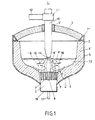
- Fig. 1 einen Vertikalschnitt durch den Lichtbogenofen mit einer Bodenelektrode in schematischer Darstellung,
- Fig. 2 eine Draufsicht auf die Bodenelektrode, und
- Fig. 3 eine vergrösserte Darstellung eines Vertikalschnittes durch die Bodenelektrode gemäss
- Fig. 2.
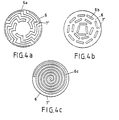
- Fig. 4a eine Draufsicht auf die Bodenelektrode in mäanderförmiger Ausbildung eines Elektrodenbestandteiles,
- Fig. 4b eine Draufsicht auf die Bodenelektrode in rechteckiger Ausbildung eines Elektrodenbestandteiles,
- Fig. 4c eine Draufsicht auf die Bodenelektrode in spiralförmiger Ausbildung beider Elektrodenbestandteile, und
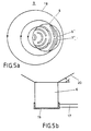
- Fig. 5a eine Draufsicht auf die Bodenelektrode gemäss Fig. 5b in schematischer Darstellung, und
- Fig. 5b eine Seitenansicht der Bodenelektrode in schematischer Darstellung.
- 1 is a vertical section through the arc furnace with a bottom electrode in a schematic representation,
- Fig. 2 is a plan view of the bottom electrode, and
- Fig. 3 is an enlarged view of a vertical section through the bottom electrode according to
- Fig. 2.
- 4a is a plan view of the bottom electrode in a meandering design of an electrode component,
- 4b is a plan view of the bottom electrode in a rectangular configuration of an electrode component,
- Fig. 4c is a plan view of the bottom electrode in a spiral configuration of both electrode components, and
- Fig. 5a is a plan view of the bottom electrode according to Fig. 5b in a schematic representation, and
- Fig. 5b is a side view of the bottom electrode in a schematic representation.
Fig. 1 zeigt den Lichtbogenofen 1 mit Ofengefäss 2 und Ofendeckel 3, wobei der Ofendeckel 3 sich mit dem Ofendeckelring 3" auf dem Ofengefäss 2 abstützt. Das Ofengefäss 2 besteht aus dem Gefässboden 4 mitsamt der feuerfesten Auskleidung 4', sowie aus der Gefässwand 5 mitsamt der feuerfesten Auskleidung 5'. Oberhalb des Schmelzbades 13 ist eine Kohlenstoffelektrode 10 angeordnet, welche durch eine Öffnung des Ofendeckels 3 hindurchragt. Zur Kühlung der Elektrode 10 ist ein Kühlring 3' vorgesehen. Die Elektrode 10 ist in einer Halterung 11 eines Elektrodentragarmes 12 gehalten. Der Elektrodentragarm 12 ist mit einer in Fig. 1 nicht dargestellten Elektrodenreguliereinrichtung verbunden.1 shows the
Im Ofengefässboden 4, 4' ist eine beispielsweise Ausführungsform der erfindungsgemässen Bodenelektrode 6 zu sehen, welche sich konisch zum Ofengefässinneren hin erweitert. Die Bodenelektrode 6 wird unterhalb des Ofengefässbodens 4 durch ein schematisch dargestelltes, als Kontakthülse ausgebildetes Anschlussstück 9 gehalten, welches gleichzeitig zur Verbindung der elektrischen Stromzuführung mittels der elektrischen Anschlussleitung 17 dient. In der Bodenelektrode 6 sind ihrem, dem Schmelzbad 13 zugewandten Teil, nichtmetallische Bestandteile 7, 8 als Einsätze in die Bodenelektrode 6 eingefügt, welche sich annähernd bis zur Hälfte der Bodenelektrode 6, in axialer Richtung betrachtet, erstrecken. Diese bestehen in der vorliegenden, in Fig. 1 dargestellten Ausführungsform, aus drei hohlzylindrischen Einsätzen 7 und einem zentralen Einsatz 8, wodurch die kreisringflächenartig ausgebildeten metallischen Bestandteile 6' der Schmelzbadkontaktfläche 6', 7' gegenseitig voneinander in schmale Zonen unterteilt werden. Die nichtmetaltischen Bestandteile 7, 8 der Bodenelektrode 6 bestehen aus einem handelsüblichen feuerfesten Baustoff, beispielsweise Dolomit oder Magnesit.An example of an embodiment of the
In Fig. 1 sind die metallischen Bestandteile 6' der Bodenelektrode 6 etwas zurückgeschmolzen und die dammartig hervorstehenden und in das Schmelzbad 13 hineinragenden Einsätze 7, 8 sind gut erkennbar. Der zwischen der Spitze der oberen Elektrode 10 und der Oberfläche des Schmelzbades 13 gebildete Lichtbogen ist mit der Bezugsziffer 14 und die elektrischen Stromlinien mit der Bezugsziffer 15 bezeichnet. In Fig. 1 sind schematisch symmetrisch zur vertikalen Ofenachse verlaufende Teilströme der Schmelzbadbewegung dargestellt, die sowohl eine axiale als auch eine radiale Komponente aufweisen. Im zentralen Bereich des Schmelzbades 13 bildet sich zunächst einmal eine axiale Aufwärtsströmung von der Bodenelektrode 6 in Richtung zum Mittelbereich des Schmelzbades 13 und zum anderen eine axiale Abwärtsströmung von der Badoberfläche in Richtung zum Mittelbereich des Schmelzbades 13, aus. Die Strömung wird dort umgelenkt und richtet sich radial nach aussen gegen die Gefässwand 5, 5'. Nach abermaliger Umlenkung verläuft die Strömung wiederum radial zum Ofeninneren hin, streicht über die als Dämme wirkenden Einsätze 7, 8 hinweg, so dass die Schmelzbadkontaktflächen 6' weitgehend unberührt bleiben.In Fig. 1, the metallic components 6 'of the
Fig. 2 zeigt in Draufsicht die Bodenelektrode 6, welche in die feuerfeste Auskleidung 4' des Ofengefässbodens 4 eingebaut ist. Die Bodenelektrode 6 weist in diesem Ausführungsbeispiel einen äusseren und einen inneren jeweils kreisringförmigen metallischen Bestandteil 6' der Schmelzbadkontaktfläche 6', 7' auf, die beide durch einen, als Damm dienenden feuerfesten Einsatz 7 voneinander getrennt sind. Der mittlere metallische Bestandteil 6' hingegen besteht aus vier kreisringförmigen Abschnitten. Diese werden gebildet, indem jeweils um 90° versetzte Durchbrüche die volle Kreisringfläche unterbrechen. In diesen Durchbrüchen befinden sich Verstrebungen 7', welche die beiden aus einem feuerfesten Baustoff bestehenden Einsätze 7 zu einem mechanisch festen Verbund vereinigen. Im Zentrum der Bodenelektrode 6 ist ein zentraler, aus feuerfestem Baustoff bestehender Einsatz 8 angeordnet. Die elektromagnetischen Feldlinien, welche um den äusseren Umfang der Bodenelektrode 6 herum verlaufen, sind durch die gestrichelte Linie mit der Bezugsziffer 18 angegeben. Senkrecht zu den Feldlinien 18 und in radialer Richtung zur Bodenelektrode 6 wirken die Kräfte, welche die Schmelzbadströmung verursachen. Sie sind durch die Pfeile mit der Bezugsziffer 16 schematisch dargestellt.Fig. 2 shows a top view of the
In Fig. 3 sind die metallischen Bestandteile 6' der Schmelzbadkontaktfläche 6', 7' sehr weit zurückgeschmolzen dargestellt. Es ist deutlich zu erkennen, dass die Schmelzbadbewegung entsprechend der Pfeilrichtung 16 über die als Dämme wirkenden Einsätze 7, 8 hinwegstreicht und die relativ schmalen kreisringförmigen Kontaktflächen 6' von der Schmelzbadbewegung 16 überhaupt nicht berührt werden. Lediglich im oberen Teil der durch die Einsätze 7, 8 gebildeten Spalten wirkt eine durch die kinetische Energie der Hauptströmung 16 angeregte Querströmung ein, die aber die Kontaktfläche 6' nicht berührt. Die Breite des nichtmetallischen Bestandteiles 7, 8 ist mit bN und diejenige des metallischen Bestandteiles 6' mit bM bezeichnet.3, the metallic components 6 'of the molten bath contact surface 6', 7 'are shown melted back very far. It can be clearly seen that the melt bath movement in the direction of the
Die abschnittsweise unterbrochene hohlzylindrische Ausbildung der Dämme 7 bietet ausserdem den Vorteil, dass beim Ausleeren der Schmelze, wenn der Lichtbogenofen gekippt wird, flüssige Anteile der Schmelze zwischen den Dämmen 7 verbleiben und dort wieder erstarren.The sectioned interrupted hollow cylindrical formation of the
Würden nämlich die flüssigen Anteile der Kontaktflächen 6' zwischen den Dämmen 7, 8 beim Ausleeren des Ofens mitausgegossen, so wäre das für den nachfolgenden Schmelzvorgang problematisch, und zwar aus folgenden Gründen: Die relativ spröden Dämme 7, 8, wären in ihrem dem Schmelzbad 13 zugewandten Teil lediglich durch die Verstrebungen 7' gehalten und der metallisch stützende Teil der Kontaktflächen würde entfallen. Dies birgt die Gefahr einer Zerstörung der oberen Teile der Dämme 7, 8 beim nachfolgenden Chargiervorgang in sich. Darüber hinaus wäre eine einwandfreie elektrische Kontaktierung zwischen den Kontaktflächen 6' und dem festen Chargiergut bei Beginn eines erneuten Schmelzvorganges infrage gestellt.If the liquid portions of the contact surfaces 6 'between the
Es ist selbstverständlich, dass eine beliebige Anzahl von Dämmen 7, 8 innerhalb der Bodenelektrode 6 angeordnet sein können. Dadurch wird bei einer vorgegebenen Stromstärke und dem damit festgelegten elektrisch leitenden Teil der Bodenelektrode 6 deren Umfang bzw. deren Durchmesser vergrössert. Je grösser aber nun der Umfang der Bodenelektrode 6 ist, umso länger werden die elektromagnetischen Feldlinien 18 und umso stärker wird die Bewegung des Schmelzbades 13 reduziert.It goes without saying that any number of
Die Einfügung von elektrisch nichtleitenden Dämmen 7, 8 in die Bodenelektrode 6 bewirkt bei gleichbleibendem leitenden Querschnitt der metallischen Kontaktfläche 6' einmal eine Herabsetzung der Schmelzbadströmung und zum anderen werden die Kontaktflächen 6' durch die Dämme 7, 8 vor unerwünschter Schmelzbadbewegung geschützt. Bei der zurückgeschmolzenen Kontaktfläche ist die Ausbildung einer Badströmung im Spalt durch dessen Enge zwischen zwei Dämmen behindert. Wegen der geringen Ausdehnung des Spaltes sind die Unterschiede der magnetischen Feldstärke im Spalt gering. Dadurch ergeben sich entsprechend geringere die Flüssigkeit antreibende Kräfte. Die Temperatur der Schmelze im Spalt entspricht oben derjenigen des überhitzten Bades und ist unten in der Nähe der Kontaktfläche etwa gleich der Schmelztemperatur. Dieser Unterschied bedeutet einen Unterschied der Dichte der Flüssigkeit, die oben leichter und unten schwerer ist. Diese Schichtung wirkt einer Bewegung (Umwälzung) der Schmelze entgegen.The insertion of electrically
In Fig. 4a bis c sind weitere Aubildungsformen des metallischen Bestandteiles 6' der Schmelzbadkontaktfläche 6', 7' der Bodenelektrode 6 dargestellt. Fig. 4a zeigt eine mäanderförmige 6a, Fig. 4b eine rechteckige 6b und Fig. 4c eine spiralförmige Ausbildung 6c des metallischen Teiles 6' der Schmelzbadkontaktfläche 6', 7', wobei jeweils komplementär dazu die nichtmetallischen, feuerfesten Bestandteile 7' eingefügt sind. Auf diese Weise ist die Bodenelektrode 6 zu einem einheitlichen Ganzen zusammengesetzt. Die Bestandteile 6', 7' der Bodenelektrode 6 können sich über die gesamte axiale Länge der Bodenelektrode 6 erstrecken. Um die elektrische Stromzuführung in die Bodenelektrode 6 in jedem Fall sicherzustellen, ist der metallische Bestandteil 6' der Bodenelektrode 6 im Bereich des elektrischen Anschlussstückes 9 über deren gesamten Durchmesser vorzugsweise kompakt ausgebildet.4a to c show further configurations of the metallic component 6 'of the molten bath contact surface 6', 7 'of the
Die geometrische Ausbildung der metallischen 6' bzw. nichtmetallischen Bestandteile 7' bleiben nicht auf die in den vorstehend gezeigten Ausführungsbeispielen beschränkt und es sind beliebig viele geometrische Formen denkbar.The geometric design of the metallic 6 'or non-metallic components 7' are not limited to the exemplary embodiments shown above and any number of geometric shapes are conceivable.
Von Bedeutung ist, dass bei einer gegebenen elektrischen Anschlussleistung des Lichtbogenofens, einmal der Querschnitt der Bodenelektrode(n) 6 möglichst gross gewählt wird, und dass zum anderen die Elektrodenbestandteile 6', 7' in Richtung der elektrischen Feldlinien verlaufen, d.h. in Umfangsrichtung der Bodenelektrode 6, wobei die Länge der Elektrodenbestandteile 6', 7' im Verhältnis zu deren Breite gross sein soll.It is important that for a given electrical connection power of the arc furnace, the cross-section of the bottom electrode (s) 6 is selected to be as large as possible, and that the electrode components 6 ', 7' run in the direction of the electrical field lines, i.e. in the circumferential direction of the
In Fig. 5a und 5b ist ein Ausführungsbeispiel dargestellt, bei dem sowohl die metallischen 6', als auch die nichtmetallischen Bestandteile 7' der Bodenelektrode 6 dem, in bezug auf die Achse der Bodenelektrode 6 nichtkonzentrischen Verlauf der magnetischen Feldlinien 18, angepasst sind. Diese Nichtkonzentrizität der magnetischen Feldlinien 18 wird hervorgerufen durch den relativ hohen elektrischen Strom, welcher durch die elektrische Anschlussleitung 17 über die Kontakthülse 19 seitlich der Bodenelektrode 6 zugeführt wird. Das daraus resultierende magnetische Feld verschiebt nun das elektromagnetische Feld in der Bodenelektrode 6 in die entgegengesetzte Richtung zur elektrischen Anschlussleitung 17. Die metallischen 6' und die nichtmetallischen Bestandteile 7' sind gemäss Fig. 5a abschnittsweise hohlzylindrisch ausgebildet und dem magnetischen Feld angepasst. Daraus ergibt sich eine asymmetrische Aufteilung der Bestandteile 6', 7' im Querschnitt der Bodenelektrode 6', wie sie in Fig. 5a zu erkennen ist.5a and 5b show an exemplary embodiment in which both the metallic 6 'and the non-metallic components 7' of the
In Fig. 5b ist schematisch dargestellt, dass die Herdfläche 20 konisch ausgebildet ist, wobei der Winkel a zwischen der Herdfläche 20 und der Schmelzbadkontaktfläche 6', 7' mindestens 20° beträgt.5b schematically shows that the
In Fig. 1 und 5b sind das Ofengefäss 4, 4'; 5, 5' und der Ofenherd 20 rotationssymmetrisch dargestellt. Es ist jedoch ebenfalls denkbar, dass die genannten Teile 4,4'; 5, 5'; 20 nicht rotationssymmetrisch ausgebildet sind. Ebenfalls bleibt die vorliegende Erfindung nicht nur auf zylindrisch ausgebildete Bodenelektroden 6 beschränkt. Es können ebenfalls ellipsenförmige, quadratische, rechteckige oder polygonale Querschnittsformen verwendet werden. Ebenso können eine oder mehrere Bodenelektroden 6 hohlzylindrisch oder zumindest abschnittsweise hohlzylindrisch ausgebildet sein.1 and 5b, the furnace vessel 4, 4 '; 5, 5 'and the
Ausserdem ist es selbstverständlich, dass eine beliebige Anzahl von Bodenelektroden 6 in den Ofengefässboden 4,4', und zwar an jeden beliebigen Ort im Ofengefässboden 4,4' eingebaut werden können.In addition, it goes without saying that any number of
Claims (10)
Priority Applications (1)
| Application Number | Priority Date | Filing Date | Title |
|---|---|---|---|
| AT84116189T ATE34901T1 (en) | 1984-01-31 | 1984-12-22 | BOTTOM ELECTRODE FOR A DIRECT CURRENT ARC FURNACE. |
Applications Claiming Priority (2)
| Application Number | Priority Date | Filing Date | Title |
|---|---|---|---|
| CH44584 | 1984-01-31 | ||
| CH445/84 | 1984-01-31 |
Publications (3)
| Publication Number | Publication Date |
|---|---|
| EP0150484A2 EP0150484A2 (en) | 1985-08-07 |
| EP0150484A3 EP0150484A3 (en) | 1985-09-25 |
| EP0150484B1 true EP0150484B1 (en) | 1988-06-01 |
Family
ID=4187187
Family Applications (1)
| Application Number | Title | Priority Date | Filing Date |
|---|---|---|---|
| EP84116189A Expired EP0150484B1 (en) | 1984-01-31 | 1984-12-22 | Bottom electrode for direct current arc furnace |
Country Status (7)
| Country | Link |
|---|---|
| US (1) | US4637033A (en) |
| EP (1) | EP0150484B1 (en) |
| JP (1) | JPS60185089A (en) |
| AT (1) | ATE34901T1 (en) |
| BR (1) | BR8500386A (en) |
| DE (1) | DE3471868D1 (en) |
| SU (1) | SU1416063A3 (en) |
Families Citing this family (10)
| Publication number | Priority date | Publication date | Assignee | Title |
|---|---|---|---|---|
| DE3817381A1 (en) * | 1988-05-18 | 1989-11-30 | Mannesmann Ag | LOW WEAR ELECTRODE IN DC ARC FURNACE |
| FR2647196B1 (en) * | 1989-05-19 | 1991-06-28 | Cezus Co Europ Zirconium | COLD CRUCIBLE DRAINED FROM THE BOTTOM |
| ES2044352T3 (en) * | 1990-09-03 | 1994-01-01 | Asea Brown Boveri | DIRECT CURRENT ELECTRIC ARC OVEN. |
| DE4129756C2 (en) * | 1991-09-04 | 1995-06-29 | Mannesmann Ag | Metallurgical vessel for a DC arc device |
| AT401303B (en) * | 1993-09-06 | 1996-08-26 | Voest Alpine Ind Anlagen | METHOD FOR PRODUCING A FLOOR ANODE FOR A METALLURGICAL VESSEL |
| FR2715941B1 (en) * | 1994-02-04 | 1996-04-19 | Clecim Sa | Direct current metal melting furnace. |
| IT1267237B1 (en) * | 1994-05-11 | 1997-01-28 | Danieli Off Mecc | COOLED BOTTOM ELECTRODE FOR A DIRECT CURRENT ELECTRIC OVEN |
| CN101786619B (en) * | 2010-02-10 | 2012-03-28 | 黎应和 | Vertical high temperature continuous graphitizing furnace |
| EA037755B1 (en) * | 2016-11-15 | 2021-05-18 | Метсо Ототек Финланд Ой | Method for controlling the electric arc in an electric arc furnace and electric arc furnace |
| CN113699306B (en) * | 2021-08-25 | 2022-04-12 | 中冶赛迪工程技术股份有限公司 | Composite bottom blowing multielement medium system and method for direct current arc furnace bottom electrode |
Citations (1)
| Publication number | Priority date | Publication date | Assignee | Title |
|---|---|---|---|---|
| DE219575C (en) * |
Family Cites Families (6)
| Publication number | Priority date | Publication date | Assignee | Title |
|---|---|---|---|---|
| GB135674A (en) * | 1900-01-01 | |||
| US1763248A (en) * | 1928-06-19 | 1930-06-10 | Pittsburgh Res Corp | Electric furnace method |
| NO123433B (en) * | 1967-06-10 | 1971-11-15 | Tohoku Special Steel Works Ltd | |
| SE419929B (en) * | 1974-11-25 | 1981-08-31 | Asea Ab | MELT CONTACT ELECTROD |
| DE2806270A1 (en) * | 1977-02-23 | 1978-08-24 | Asea Ab | FUSION CONTACT ELECTRODE |
| FR2441313A1 (en) * | 1978-11-10 | 1980-06-06 | Siderurgie Fse Inst Rech | COOLED ELECTRODE FOR CONTACT WITH FUSED METAL |
-
1984
- 1984-12-22 EP EP84116189A patent/EP0150484B1/en not_active Expired
- 1984-12-22 DE DE8484116189T patent/DE3471868D1/en not_active Expired
- 1984-12-22 AT AT84116189T patent/ATE34901T1/en not_active IP Right Cessation
-
1985
- 1985-01-24 US US06/694,301 patent/US4637033A/en not_active Expired - Fee Related
- 1985-01-28 SU SU853843338A patent/SU1416063A3/en active
- 1985-01-29 BR BR8500386A patent/BR8500386A/en not_active IP Right Cessation
- 1985-01-30 JP JP60014632A patent/JPS60185089A/en active Pending
Patent Citations (1)
| Publication number | Priority date | Publication date | Assignee | Title |
|---|---|---|---|---|
| DE219575C (en) * |
Also Published As
| Publication number | Publication date |
|---|---|
| DE3471868D1 (en) | 1988-07-07 |
| JPS60185089A (en) | 1985-09-20 |
| ATE34901T1 (en) | 1988-06-15 |
| US4637033A (en) | 1987-01-13 |
| EP0150484A2 (en) | 1985-08-07 |
| SU1416063A3 (en) | 1988-08-07 |
| EP0150484A3 (en) | 1985-09-25 |
| BR8500386A (en) | 1985-09-10 |
Similar Documents
| Publication | Publication Date | Title |
|---|---|---|
| DE3106741C2 (en) | Contact electrode arrangement for arc or resistance melting furnace | |
| EP0150484B1 (en) | Bottom electrode for direct current arc furnace | |
| DE3107454C2 (en) | ||
| DE1952407A1 (en) | Arc melting furnace | |
| DE2300341A1 (en) | ARC FURNACE FOR FINE METAL, IN PARTICULAR DC FLOW ARC FURNACE FOR MELTING AND FINE STEEL SCRAP | |
| DE2621380B2 (en) | Melting furnace with a container for melting material | |
| DD242925A5 (en) | ELECTRICAL CONNECTION DEVICE FOR INSERTING IN THE WALL OF THE METALLURGICAL CONTAINER OF AN ELECTRIC DC POWER SUPPLY | |
| EP0150483B1 (en) | Bottom electrode arrangement for an electric furance | |
| EP0133925A1 (en) | Bottom electrode arrangement for a direct current arc furnace | |
| EP0103534B1 (en) | Crucible furnace | |
| DE2550671A1 (en) | FUSION CONTACT ELECTRODE FOR A DIRECT CURRENT ARC FURNACE | |
| EP0422406B1 (en) | Anode for direct current arc furnace | |
| DE4335065C2 (en) | Bottom electrode for a metallurgical vessel operated with direct current | |
| EP4074144A1 (en) | Electric arc furnace and method for operating an electric arc furnace | |
| DE2525720C2 (en) | Melt contact electrode for an electric arc furnace fed with direct current | |
| EP0541044A2 (en) | DC arc furnace | |
| DE3242209C2 (en) | ||
| EP0167037B1 (en) | Bottom electrode for pouring ladles | |
| EP0133926B1 (en) | Bottom electrode for a direct current arc furnace | |
| DE4022720A1 (en) | UNDERWAY OF A DC ARC FURNACE | |
| EP0540832B1 (en) | Anode for a direct-current arc furnace | |
| DE3817381C2 (en) | ||
| EP0273975A1 (en) | Induction plasma furnace | |
| DE312569C (en) | ||
| DE505169C (en) | Device for supplying power to the electrodes of an electric oven |
Legal Events
| Date | Code | Title | Description |
|---|---|---|---|
| PUAI | Public reference made under article 153(3) epc to a published international application that has entered the european phase |
Free format text: ORIGINAL CODE: 0009012 |
|
| PUAL | Search report despatched |
Free format text: ORIGINAL CODE: 0009013 |
|
| AK | Designated contracting states |
Designated state(s): AT CH DE FR GB IT LI SE |
|
| AK | Designated contracting states |
Designated state(s): AT CH DE FR GB IT LI SE |
|
| 17P | Request for examination filed |
Effective date: 19851010 |
|
| 17Q | First examination report despatched |
Effective date: 19870108 |
|
| RAP1 | Party data changed (applicant data changed or rights of an application transferred) |
Owner name: BBC BROWN BOVERI AG |
|
| GRAA | (expected) grant |
Free format text: ORIGINAL CODE: 0009210 |
|
| AK | Designated contracting states |
Kind code of ref document: B1 Designated state(s): AT CH DE FR GB IT LI SE |
|
| REF | Corresponds to: |
Ref document number: 34901 Country of ref document: AT Date of ref document: 19880615 Kind code of ref document: T |
|
| ITF | It: translation for a ep patent filed |
Owner name: DE DOMINICIS & MAYER S.R.L. |
|
| REF | Corresponds to: |
Ref document number: 3471868 Country of ref document: DE Date of ref document: 19880707 |
|
| ET | Fr: translation filed | ||
| GBT | Gb: translation of ep patent filed (gb section 77(6)(a)/1977) | ||
| PLBE | No opposition filed within time limit |
Free format text: ORIGINAL CODE: 0009261 |
|
| STAA | Information on the status of an ep patent application or granted ep patent |
Free format text: STATUS: NO OPPOSITION FILED WITHIN TIME LIMIT |
|
| 26N | No opposition filed | ||
| ITTA | It: last paid annual fee | ||
| PGFP | Annual fee paid to national office [announced via postgrant information from national office to epo] |
Ref country code: GB Payment date: 19931115 Year of fee payment: 10 |
|
| PGFP | Annual fee paid to national office [announced via postgrant information from national office to epo] |
Ref country code: SE Payment date: 19931116 Year of fee payment: 10 |
|
| PGFP | Annual fee paid to national office [announced via postgrant information from national office to epo] |
Ref country code: FR Payment date: 19931119 Year of fee payment: 10 Ref country code: AT Payment date: 19931119 Year of fee payment: 10 |
|
| PGFP | Annual fee paid to national office [announced via postgrant information from national office to epo] |
Ref country code: DE Payment date: 19940214 Year of fee payment: 10 |
|
| PGFP | Annual fee paid to national office [announced via postgrant information from national office to epo] |
Ref country code: CH Payment date: 19940314 Year of fee payment: 10 |
|
| PG25 | Lapsed in a contracting state [announced via postgrant information from national office to epo] |
Ref country code: GB Effective date: 19941222 Ref country code: AT Effective date: 19941222 |
|
| PG25 | Lapsed in a contracting state [announced via postgrant information from national office to epo] |
Ref country code: SE Effective date: 19941223 |
|
| PG25 | Lapsed in a contracting state [announced via postgrant information from national office to epo] |
Ref country code: LI Effective date: 19941231 Ref country code: CH Effective date: 19941231 |
|
| EAL | Se: european patent in force in sweden |
Ref document number: 84116189.6 |
|
| GBPC | Gb: european patent ceased through non-payment of renewal fee |
Effective date: 19941222 |
|
| PG25 | Lapsed in a contracting state [announced via postgrant information from national office to epo] |
Ref country code: FR Effective date: 19950831 |
|
| REG | Reference to a national code |
Ref country code: CH Ref legal event code: PL |
|
| PG25 | Lapsed in a contracting state [announced via postgrant information from national office to epo] |
Ref country code: DE Effective date: 19950901 |
|
| EUG | Se: european patent has lapsed |
Ref document number: 84116189.6 |
|
| REG | Reference to a national code |
Ref country code: FR Ref legal event code: ST |