EP0273975A1 - Induction plasma furnace - Google Patents
Induction plasma furnace Download PDFInfo
- Publication number
- EP0273975A1 EP0273975A1 EP86906036A EP86906036A EP0273975A1 EP 0273975 A1 EP0273975 A1 EP 0273975A1 EP 86906036 A EP86906036 A EP 86906036A EP 86906036 A EP86906036 A EP 86906036A EP 0273975 A1 EP0273975 A1 EP 0273975A1
- Authority
- EP
- European Patent Office
- Prior art keywords
- melt
- crucible
- plasmatron
- sections
- inductor
- Prior art date
- Legal status (The legal status is an assumption and is not a legal conclusion. Google has not performed a legal analysis and makes no representation as to the accuracy of the status listed.)
- Granted
Links
Images

Classifications
-
- H—ELECTRICITY
- H05—ELECTRIC TECHNIQUES NOT OTHERWISE PROVIDED FOR
- H05B—ELECTRIC HEATING; ELECTRIC LIGHT SOURCES NOT OTHERWISE PROVIDED FOR; CIRCUIT ARRANGEMENTS FOR ELECTRIC LIGHT SOURCES, IN GENERAL
- H05B11/00—Heating by combined application of processes covered by two or more of groups H05B3/00 - H05B7/00
-
- F—MECHANICAL ENGINEERING; LIGHTING; HEATING; WEAPONS; BLASTING
- F27—FURNACES; KILNS; OVENS; RETORTS
- F27B—FURNACES, KILNS, OVENS, OR RETORTS IN GENERAL; OPEN SINTERING OR LIKE APPARATUS
- F27B14/00—Crucible or pot furnaces
- F27B14/06—Crucible or pot furnaces heated electrically, e.g. induction crucible furnaces with or without any other source of heat
- F27B14/061—Induction furnaces
-
- F—MECHANICAL ENGINEERING; LIGHTING; HEATING; WEAPONS; BLASTING
- F27—FURNACES; KILNS; OVENS; RETORTS
- F27B—FURNACES, KILNS, OVENS, OR RETORTS IN GENERAL; OPEN SINTERING OR LIKE APPARATUS
- F27B14/00—Crucible or pot furnaces
- F27B14/08—Details peculiar to crucible or pot furnaces
- F27B14/14—Arrangements of heating devices
-
- F—MECHANICAL ENGINEERING; LIGHTING; HEATING; WEAPONS; BLASTING
- F27—FURNACES; KILNS; OVENS; RETORTS
- F27D—DETAILS OR ACCESSORIES OF FURNACES, KILNS, OVENS, OR RETORTS, IN SO FAR AS THEY ARE OF KINDS OCCURRING IN MORE THAN ONE KIND OF FURNACE
- F27D99/00—Subject matter not provided for in other groups of this subclass
- F27D99/0001—Heating elements or systems
- F27D99/0006—Electric heating elements or system
-
- H—ELECTRICITY
- H05—ELECTRIC TECHNIQUES NOT OTHERWISE PROVIDED FOR
- H05B—ELECTRIC HEATING; ELECTRIC LIGHT SOURCES NOT OTHERWISE PROVIDED FOR; CIRCUIT ARRANGEMENTS FOR ELECTRIC LIGHT SOURCES, IN GENERAL
- H05B6/00—Heating by electric, magnetic or electromagnetic fields
- H05B6/02—Induction heating
- H05B6/22—Furnaces without an endless core
-
- F—MECHANICAL ENGINEERING; LIGHTING; HEATING; WEAPONS; BLASTING
- F27—FURNACES; KILNS; OVENS; RETORTS
- F27D—DETAILS OR ACCESSORIES OF FURNACES, KILNS, OVENS, OR RETORTS, IN SO FAR AS THEY ARE OF KINDS OCCURRING IN MORE THAN ONE KIND OF FURNACE
- F27D99/00—Subject matter not provided for in other groups of this subclass
- F27D99/0001—Heating elements or systems
- F27D99/0006—Electric heating elements or system
- F27D2099/0031—Plasma-torch heating
Definitions
- the invention relates to a field of electrical engineering and is particularly concerned with electrical heaters, namely a plasma induction furnace.
- the performance of different melting furnaces and the quality of the metal or alloy to be produced depend significantly on the type and intensity of movement of the melt in the crucible.
- Induction melting furnaces are largely known which contain an inductor with a crucible arranged therein, which is lined with a refractory lining. They ensure contactless energy supply to the insert in the crucible, i.e. Batch, melt or batch-melt mixture.
- the insert is mixed using the electromagnetic field of the inductor.
- devices are used in which the circulation of the insert is generated in a circuit with the aid of a running field which ensures that the insert is mixed over the entire crucible height while reducing the meniscus (AESlukhotsky , VSNemkov, NAPavlov, AVBamune, Ustanovka induktsionnogo nagreva. Energoizdat, Leningradskoe otdelenie / induction heating system, publisher Energoizdat, Leningrader Department /, 1981, pp. 246 to 247).
- the insert can be heated and mixed both simultaneously and alternately.
- inductors a single-phase inductor for heating and a three-phase inductor for mixing, which uses electrostatic filters to protect the feed source against intrusion into which others are equipped.
- the oven has a divided inductor, which is alternately connected to different food sources.
- the supply circuit of the induction melting furnace is considerably complicated, only two types of circulation are generated: in two circuits - when connecting the inductor to a single-phase supply source, in a circuit - when connecting it to a three-phase supply source.
- Plasmo induction furnaces which contain an inductor with a crucible arranged therein and an arc plasmatron, the circuit of which is closed via the melt.
- these furnaces make it possible, for example, to double the productivity of the process of melting metals and alloys, due to the combination of the local and the spatial heating of the insert.
- the quality of the metals and alloys to be produced is improved due to the in-depth refining of the melt to remove non-metallic inclusions and harmful substances.
- the melt be treated with both inert and active plasma-forming gases. How the mixing process of use in plasma induction furnaces takes place is therefore of particular importance for the performance increase of the furnaces and the quality improvement of the metals and alloys to be obtained by melting.
- a plasma induction furnace which contains an inductor with a crucible arranged therein, the side wall of which is cylindrical, and an arc plasmatron, the circuit of which is closed via the 5 melt located in the crucible (S.Asada. Dvukhtonnaya plazmenno-induktsionnaya pech na zavode g.Sibukava / 2 t - plasma induction furnace in the city factory Sibukava /, "Denki seiko", volume 47, No. T, 1976, pp. 60 to 63).
- the inner surface of the crucible is made of an electrical insulating material, and it is provided with a magnesite lining and provides the electrical insulation of the plasmatron circuit from the inductor circuit.
- a bottom electrode for closing the plasmatron circuit is arranged in the bottom of the crucible.
- the inductor is connected to a single-phase supply source with an output frequency of 150 Hz.
- a three-phase system for electromagnetic mixing is provided, which contains three inductors, each of which is connected to a phase of a three-phase supply source with a frequency of 60 Hz.
- the invention has for its object a To create a plasma induction furnace with such a design of the crucible and such an electrical coupling of the crucible with a plasmatron, by means of which a predetermined type of circulation of the melt in the crucible can be generated depending on the technological process during the melting process and thus the performance of the plasma induction furnace can be increased.
- the object is achieved in that, in the case of a plasma induction furnace which contains an inductor with a crucible arranged therein, the side wall of which is cylindrical, and an arc plasmatron, the circuit of which is closed via the melt located in the crucible, according to the invention the side wall of the crucible is perpendicular arranged sections is formed, which consist of a current-conducting material and are electrically insulated from one another, at least one of which is connected in series in the plasmatron circuit in such a way that the current direction in the plasmatron arc coincides with the current direction in the crucible section or is opposite thereto.
- Such a constructive design of the crucible of the plasma induction furnace allows a predetermined type of circulation of the melt, depending on the technological process stage when metals and alloys are melted, due to the electromagnetic interaction of fields generated by the inductor current and the current in the sections of the crucible with those flowing in the melt Streams are created.
- the constructive design of the crucible according to the invention thus allows any type of circulation of the melt, which is required depending on the technological process step when melting metals or alloys, to be produced in the plasma induction furnace without the structure of the furnace having to be considerably complicated.
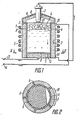
- the plasma induction furnace contains an inductor 1 (FIG. 1) with a crucible 2 arranged therein.
- the inductor is designed in the form of a tube with a round or special cross-section, which lies near the helix around the crucible 2.
- the crucible 2 has the shape of a cylinder, its side wall being formed by vertically arranged sections 3 (FIGS. 1, 2) which consist of a current-conducting material, in particular of metal ceramic.
- sections 3 In the embodiment of the plasma induction furnace shown in FIGS. 1, 2, five sections 3 are shown. Depending on the outer dimensions of the crucible 2, the number and the material of these sections 3 can be different. It is expedient that S etechnischsaniere within 5 to 35 select, which optimal energy parameters of the plasma induction furnace z . B. the efficiency, the performance can be guaranteed.
- the sections 3 of the crucible 2 can also be made from other current-conducting materials such as graphite, metal.
- the sections 3 are electrically insulated from one another by electro-insulating layers 6 consisting of magnesite, which lie between the sections 3 and have been applied to the surfaces of the sections 3 facing the inside of the crucible 2, to the bottom 5, to the end faces of the sections 3.
- the thickness of each layer 6 depends on the material and application method of the electrical insulation.
- the electrical insulation made of Al203 can, for example, be applied using the vapor deposition method.
- the plasma induction furnace also contains a DC arc plasmatron 7 (Fig. 1).
- the plasmatron 7 is mounted in the lid 8 of the crucible 2 and causes the batch 9 to be heated and melted down with the aid of a plasma arc 10.
- the inner surface of the lid 8 is provided with a lining layer 11.
- a segment-shaped part 12 (FIG. 2) of the crucible 2 (FIG. 1) lying in the vicinity of one of the sections 3 of the crucible 2 is insulation-free.
- This part 12 (FIG. 2) serves to supply current to the melt 4 (FIG. 1), via which the circuit of the plasmatron 7 is closed.
- the section 3 of the crucible 2, to which the part 12 (FIG. 2) of the base 5 (FIG. 1) adjoins, is connected to the circuit of the plasmatron 7.
- the current direction in the arc of the plasmatron 1 0 7 coincides with the direction of current in the section 3 together (in Fig. 1, the current directions are indicated with arrows).
- Power supply terminals 13, 14 of the plasma t rons 7 are connected to a supply source, in the embodiment in question - to a direct current source.
- An AC power source can be used as the power source. If a DC plasmatron is used it is connected to the AC power source via a rectifier. Only one AC power source is used for the AC plasmatron. When using an AC power source, a power source can be used for the inductor.
- one of the terminals - 13 - is connected to the bottom 5 of the crucible 2 and the other terminal 14 to a power supply 15 arranged in the upper part of section 3, while another power supply 16, which is located in the lower part of this section 3, with the plasmatron 7 is connected.
- the section 3 to the power is - _ circle of the plasmatron 7 connected so that the Stremcardien in opposite directions in the section 3 and in the arc 10 of the plasmatron 7.
- the power supply 15 is connected to the terminal 13 and the Plasmatron 7 to the terminal 14.
- the bottom 5 of the crucible 2 is completely covered with the electrical insulating layer 6, while a part 17 of the inner surface of the section 3, which is connected to the circuit of the plasmatron 7, is insulation-free and serves to supply current to the melt 4.
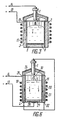
- Fig. 4 shows a plasma induction furnace, the crucible 18, which is enclosed by an inductor 19 designed in a known manner, contains twelve sections 20 (Fig. 5), which are designed with a cooled composite crucible as in known induction furnaces.
- Each section 20 is made of a metal, e.g. made of copper, and has a circulation channel 21 for a coolant, as which water, gas, cryogenic liquid can be used.
- the sections 20 are electrically isolated from one another with the aid of electrical insulating layers 22, 23, for example made of Al 2 O 3 , which have been applied by vapor deposition to the surfaces facing the inside of the crucible 18 and to one another.
- electrical insulating layers 22, 23, for example made of Al 2 O 3 which have been applied by vapor deposition to the surfaces facing the inside of the crucible 18 and to one another.
- an electric device can also be used insulating layer, for example made of magnesite or alundum.
- the lid 24 of the crucible 18 was made similar to the lid 8.
- a coolant circulation channel 28 is provided in the bottom 27, and the surface of the bottom 27 facing the interior of the crucible 18 is covered with an electrical insulating layer 29.
- an annular part 30 (FIG. 5) of the base 27 adjoining the sections 18 is insulation-free.
- FIG. 6 shows an embodiment of the plasma induction furnace similar to that shown in FIGS. 4, 5, in which all sections 20 of the crucible 18 are connected to the circuit of the plasma cartridge 7 in such a way that the current directions in the arc 10 and in the sections 20 coincide .
- the current leads 31 arranged in the upper part of the sections 20 are connected to the terminal 14 and the current leads 32 located in the lower part of the sections 20 are connected to the Plasmatron 7.
- the bottom 27 is completely insulation-free and connected to the terminal 13.
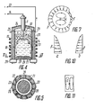
- the force F of the electromagnetic field on the melt 4 is indicated in FIG. 7, 8a, b, 10a, b, 12a, b with arrows.
- the type of circulation of the melt 4 is in the plasma induction furnaces shown in FIGS. 1, 2, 3, 4, 5, 6 with closed lines "1" in FIG . 7, 9, 11, 13 indicated.
- the plasma induction furnace is operated as follows.
- the cover 8 is closed and the plasmatron 7 is brought into the ignition position of the arc 10. Then a voltage is supplied to the inductor 1 and the plasmatron 7 and the arc 10 is ignited.
- the insert Under the action of the arc 10 of the plasmatron 7 and the electromagnetic field of the inductor 1, the insert begins to melt down.
- the arc 10 melts the insert layer quickly through its thickness, burns between the surface of the melt 4 and the plasmatron 7 and gives off its heat intensively to the surrounding insert.
- the length of the arc 10 becomes shorter, the conditions for the heat emission from the arc 10 to the melt 4 deteriorate.
- the conditions for supplying energy from the inductor 1 to the melt 4 are improved.
- the force F (FIG. 7) on the melt 4 (FIG. 1) is weakened by the section 3 connected to the circuit of the plasmatron 7, which leads to the circulation of the melt 4 in the horizontal plane in the entire volume of the crucible 2.
- the surface of the melt 4 has no meniscus, and a continuous supply of the slag under the arc 10 of the plasmatron 7 is ensured, its melting and heating accelerating, which leads to an increase in the furnace output.
- the homogeneity of the melt 4 in the total volume of the crucible 2 is also improved.
- This constructive design of the crucible 2 makes it possible to rapidly change the type of movement of the melt from the circulation in the vertical plane to the circulation in the horizontal plane by continuously changing the current in the inductor 1 or in the arc 10 of the plasmatron 7.
- Refractory metals and alloys e.g. Tungsten are usually melted in a plasma induction furnace with the cooling crucible 18 (FIGS. 4, 5, 6).
- a coolant is introduced into the channels 21 of the sections 20 and the channel 28 of the base 27, which coolant circulates during the entire melting process.
- the arc 10 is ignited.
- a section flows through the sections 20 connected to the circuit of the plasma cartridge 7, the direction of which is opposite to the current direction in the arc 10 of the plasma cartridge 7.
- the melt 4 is mixed thoroughly, and the surface of the melt 4 acquires a convex shape.
- the current of the arc 10 flowing through the melt 4 will strive to flow along the surface of the melt 4 in the vicinity of the electrically insulated sections 20 connected to the circuit of the plasma cartridge 7.
- a component of the force of the electromagnetic field of the sections 20 on the current flowing through the arc 10 and the melt 4 thus arises in the upper part of the melt 4 and is directed downward to the bottom 27 of the crucible 18.
- the size of this component decreases.
- the component directed from the periphery towards the center of the melt 4 of the similar interaction of the electromagnetic field generated by the current in the sections 20 with the current flowing through the melt 4 increases, thereby pushing back. the melt 4 is increased by the sections 20 of the crucible 18.
- the specific power to be supplied by the inductor 19 can be increased in that, as a result of the connection of the sections 20 of the crucible 18, their current direction with the current direction in the arc 1: 0 of the plasmatron 7 coincides, the resulting force F (FIG. 12a, b) of the electromagnetic field from the inductor 19 on the melt 4 (FIG. 6) can be weakened on the circuit of the plasmatron 7.
- the circulation type "1" (Fig. 13) is similar to the circulation taking place under the effect of the electromagnetic field from the inductor 19, only the speed of movement of the melt 4 changes Period through the inductor 19 of the melt 4 to be supplied leads to an increase in the furnace output.
- the present plasma induction furnace can preferably be used in the metallurgical industry, in technological processes when melting different metals and alloys, e.g. on the tungsten, molybdenum basis, especially in processes associated with the use of highly active hot slags.
Abstract
Description
Die Erfindung beziehtdsich auf ein Gebiet dein Elektrotechnik und betrifft insbesondere elektrische Heizeinrichtungen, und zwar einen Plasmainduktionsofen.The invention relates to a field of electrical engineering and is particularly concerned with electrical heaters, namely a plasma induction furnace.
Die Leistung verschiedener Schmelzöfen und die Güte des zu erzeugenden Metalls oder der Legierung sind von der Bewegungsart und -intensität der Schmelze im Schmelztiegel bedeutend abhängig.The performance of different melting furnaces and the quality of the metal or alloy to be produced depend significantly on the type and intensity of movement of the melt in the crucible.
Jeder der technologischen Vorgängen beim Schmelzen eines Metalls oder einer Legierung wie Herunterschmelzen der Charge, Überhitzung des gesamten Schmelzvolumens, Temperaturausgleich im Gesamtvolumen der Schmelze, Gewinnung einer homogenen ihrer Zusammensetzung nach Schmelze sowie Diffusionsvorgänge sowohl in der Schmelze selbst, als auch an der Grenze "Schmelze-Schlacke", "Atmosphäre-Schmelze" werden durch die zwangsläufige Mischung intensiviert, wodurch die Produktivität des Prozesses im ganzen letzten Endes beträchtlich gesteigert wird.Each of the technological processes involved in melting a metal or an alloy, such as melting down the batch, overheating the entire melting volume, temperature compensation in the total volume of the melt, obtaining a homogeneous composition after the melt, and diffusion processes both in the melt itself and at the "melting point" Slag "," atmosphere melt "are intensified by the inevitable mixing, whereby the productivity of the process in the end is increased considerably.
Es sind Induktionsschmelzofen weitgehend bekannt, die einen Induktor mit einem darin angeordneten Schmelztiegel enthalten, der mit einem feuerfesten Futter ausgekleidet ist. Sie sorgen für eine kontaktlose Energiezufuhr an den im Tiegel befindlichen Einsatz, d.h. Charge, Schmelze oder Charge-Schmelze-Gemisch. Der Einsatz wird mit Hilfe des elektromagnetischen Feldes des Induktors durchgemischt.Induction melting furnaces are largely known which contain an inductor with a crucible arranged therein, which is lined with a refractory lining. They ensure contactless energy supply to the insert in the crucible, i.e. Batch, melt or batch-melt mixture. The insert is mixed using the electromagnetic field of the inductor.
In bei normaler Frequenz (50 bis 60 Hz) betriebenen Induktionsschmelzöfen ist die Geschwindigkeit der Scmelze hoch, wodurch ein wirksames Schmelzen des festen Einsatzes und die Homogenisierung der Schmelze gewährleistet werden. Dabei sind jedoch ein verstärkter Verschleiss des Tiegelfutters und eine erhöhte Oxydation der Schmelze zu verzeichnen, was zur Verunreinigung des Metalls mit Einschlüssen verschiedener. Art führt. Dabei ist ein Metallauswurf aus dem Tiegel möglich- Solche Induktionsöfen haben daher eine Begrenzung in bezug auf die zuzuführende spezifische Leistung innerhalb 300 bis 400 kW/t.In induction melting furnaces operated at normal frequency (50 to 60 Hz), the speed of the melt is high, which ensures effective melting of the fixed insert and homogenization of the melt. However, there is increased wear of the crucible chuck and increased oxidation of the melt, which leads to contamination of the metal with inclusions of various types. Kind of leads. A metal ejection from the crucible is possible - such induction furnaces therefore have a limit in relation to the specific power to be supplied within 300 to 400 kW / t.
In bei einer erhöhten Frequenz (150 bis 10000 Hz) betriebenen Öfen kann die zuzuführende spezifische Leistung vergrössert werden, aber die Bewegungsgeschwindigkeit der Schmelze ist in diesen Öfen bedeutend niedriger.In furnaces operated at an increased frequency (150 to 10,000 Hz), the specific power to be supplied can be increased, but the speed of movement of the melt is significantly lower in these furnaces.
Bekanntlich erfolgt die natürliche Zirkulation in Induktionsschmelzöfen, bei denen der Induktor an eine einphasige Speisequelle angeschlossen ist, in zwei Kreisläufen, die in Vertikalebene, im Ober- und Unterteil des Tiegels liegen, in jedem von denen die Schmelze des Einsatzes getrennt zirkuliert, indem eine Vermischung schwach vor sich geht. Eine solche Zirkulationsart in Induktionsöfen führt zur Entstehung eines konvexen Meniskus an der Schmelzenoberfläche, wodurch die erforderliche Men- ge Schlacke vergrössert wird, die zu den Wandungen des Tiegels herunterrollt, dessen Futter zerstört und die Schmelze verunreinigt.As is known, natural circulation in induction melting furnaces, in which the inductor is connected to a single-phase supply source, takes place in two circuits, which lie in the vertical plane, in the upper and lower part of the crucible, in each of which the melt of the insert circulates separately, by mixing is going on weakly. Such a circulation type in induction leads to the formation of a convex meniscus at the melt surface, whereby the required Men - ge slag is increased, the rolling down to the walls of the crucible, the feed destroyed and contaminating the melt.
Ausserdem führt die Vergrösserung der Schlackenmenge zur Herabsetzung der Raffinierfähigkeit der Schmelze,da die Schlacke durch den Wärmeübergang von der Schmelze erhitzt wird.In addition, the increase in the amount of slag leads to a reduction in the refinability of the melt, since the slag is heated by the heat transfer from the melt.
Um das elektrodynamische Vermischen der Schmelze in Induktionsschmelzöfen verbessern zu können, werden Einrichtungen verwendet, in denen mit Hilfe eines Lauffeldes, das ein Mischen des Einsatzes auf der ganzen Tiegelhöhe unter Verkleinerung des Meniskus gewährleistet, die Zirkulation des Einsatzes in einem Kreislauf erzeugt wird (A.E.Slukhotsky, V.S.Nemkov, N.A.Pavlov, A.V.Bamune, Ustanovka induktsionnogo nagreva. Energoizdat, Leningradskoe otdelenie/ Induktionserwärmungsanlage, Verlag Energoizdat, Leningrader Abteilung/, 1981, S.246 bis 247).In order to be able to improve the electrodynamic mixing of the melt in induction melting furnaces, devices are used in which the circulation of the insert is generated in a circuit with the aid of a running field which ensures that the insert is mixed over the entire crucible height while reducing the meniscus (AESlukhotsky , VSNemkov, NAPavlov, AVBamune, Ustanovka induktsionnogo nagreva. Energoizdat, Leningradskoe otdelenie / induction heating system, publisher Energoizdat, Leningrader Department /, 1981, pp. 246 to 247).
Die Erhitzung und Durchmischung des Einsatzes können sowohl gleichzeitig, als auch abwechselnd erfolgen. Im ersten Fall werden getrennte Induktoren verwendet: ein einphasiger Induktor zur Erhitzung und ein dreiphasiger Induktor zur Durchmischung, die mit Elektrofiltern zum Schutz der Speisequelle gegen Eindringen eine Frequenz in die andere ausgerüstet sind. Im zweiten Fall hat der Ofen einen unterteilten Induktor, der abwechselnd an verschiedene Speisequellen angeschlossen wird. Bei einer beträchtlichen Komplizierung der Speiseschaltung des Induktionsschmelzofens werden jedoch nur zwei Zirkulationsarten erzeugt: in zwei Kreisläufen - beim Anschluss des Induktors an eine einphasige Speisequelle, in einem Kreislauf - bei seinem Anschluss an eine dreiphasige Speisequelle.The insert can be heated and mixed both simultaneously and alternately. In the first case, separate inductors are used: a single-phase inductor for heating and a three-phase inductor for mixing, which uses electrostatic filters to protect the feed source against intrusion into which others are equipped. In the second case, the oven has a divided inductor, which is alternately connected to different food sources. However, if the supply circuit of the induction melting furnace is considerably complicated, only two types of circulation are generated: in two circuits - when connecting the inductor to a single-phase supply source, in a circuit - when connecting it to a three-phase supply source.
Es sind Plasmoinduktionsöfen bekannt, die einen Induktor mit einem darin angeordneten Schmelztiegel und ein Lichtbogenplasmatron enthalten, dessen Stromkreis über die Schmelze geschlossen wird. Im Vergleich zu den Induktionsschmelzöfen gestatten diese Öfen es, auf Grund der Vereinigung der örtlichen und der räumlichen Erhitzung des Einsatzes die Produktivität des Prozesses der Erschmelzung von Metallen und Legierungen wesentlich beispielsweise um das Doppelte zu steigern. Durch Erhitzen der Schlacken mit Hilfe des Plasmalichtbogens des Lichtbogenplasmatrons wird die Güte der zu erzeugenden Metalle und Legierungen auf Grund der Durchführung einer tiefgehenden Raffination der Schmelze zum Entfernen nichtmetallischer Einschlüsse und schädlucher Begleitstoffe verbessert.Plasmo induction furnaces are known which contain an inductor with a crucible arranged therein and an arc plasmatron, the circuit of which is closed via the melt. In comparison to induction melting furnaces, these furnaces make it possible, for example, to double the productivity of the process of melting metals and alloys, due to the combination of the local and the spatial heating of the insert. By heating the slags with the help of the plasma arc of the arc plasma matron, the quality of the metals and alloys to be produced is improved due to the in-depth refining of the melt to remove non-metallic inclusions and harmful substances.
Dank der Verwendung des Plasmatrons kann die Schmelze ; sowohl mit inerten, als auch aktiven plasmabildenden Gasen behandelt werden. Wie der Durchmischungsvorgang des Einsatzes in Plasmainduktionsöfenveranstaltet ist, ist daher von besonderer Bedeutung für die Leistungssteigerung der Öfen und die Güteverbesserung der durch Schmelzen zu gewinnenden )Metalle und Legierungen.Thanks to the use of the plasmatron, the melt; be treated with both inert and active plasma-forming gases. How the mixing process of use in plasma induction furnaces takes place is therefore of particular importance for the performance increase of the furnaces and the quality improvement of the metals and alloys to be obtained by melting.
Es ist ebenfalls ein Plasmainduktionsofen bekannt, der einen Induktor mit einem darin angeordneten Schmelztiegel, dessen Seitenwand zylinderförmig ausgebildet ist, und ein Lichtbogenplasmatron enthält, dessen Stromkreis über die 5 im Tiegel befindliche Schmelze geschlossen wird (S.Asada. Dvukhtonnaya plazmenno-induktsionnaya pech na zavode g.Sibukava/ 2 t - Plasmainduktionsofen im Werk der Stadt Sibukava/, "Denki seiko", Band 47, Nr. T, 1976, S. 60 bis 63). Die Innenfläche des Tiegels besteht aus einem Elektroisoliermaterial, u.z. ist mit einem Magnesitfutter versehen und sorgt für die elektrische Isolation des Plasmatronstromkreises gegen den Induktorstromkreis.A plasma induction furnace is also known, which contains an inductor with a crucible arranged therein, the side wall of which is cylindrical, and an arc plasmatron, the circuit of which is closed via the 5 melt located in the crucible (S.Asada. Dvukhtonnaya plazmenno-induktsionnaya pech na zavode g.Sibukava / 2 t - plasma induction furnace in the city factory Sibukava /, "Denki seiko", volume 47, No. T, 1976, pp. 60 to 63). The inner surface of the crucible is made of an electrical insulating material, and it is provided with a magnesite lining and provides the electrical insulation of the plasmatron circuit from the inductor circuit.
Im Boden des Schmelztiegels ist eine Bodenelektrode zum Schliessen des Plasmatronstromkreises angeordnet. Der Induktor ist an eine einphasige Speisequelle mit 150 Hz Ausgangsfrequenz angeschlossen. Zum Durchmischen der Schmelze im gesamten Volumen des Tiegels ist ein Dreiphasensystem für die elektromagentische Durchmischung vorgesehen, das drei Induktoren enthält, jeder von denen an eine Phase einer dreiphasigen Speisequelle mit 60 Hz Frequenz angeschlossen ist. Durch dieses System kann die Zirkulation der Schmelze in zwei Kreisläufen auf die Zirkulation in einem Kreislauf und umgekehrt geändert werden. Die Richtung der Zirkulation in einem Kreislauf kann durch entsprechende Umschaltungen in der Speiseschaltung geändert werden.A bottom electrode for closing the plasmatron circuit is arranged in the bottom of the crucible. The inductor is connected to a single-phase supply source with an output frequency of 150 Hz. To mix the melt in the entire volume of the crucible, a three-phase system for electromagnetic mixing is provided, which contains three inductors, each of which is connected to a phase of a three-phase supply source with a frequency of 60 Hz. With this system, the circulation of the melt in two circuits can be changed to the circulation in one circuit and vice versa. The direction of the circulation in a circuit can be changed by appropriate switches in the feed circuit.
Durch solch eine konstruktive Ausführung des Plasmainduktionsofens wird die Bauart des Ofens wesentlich kompliziert werden die Aussenabmessungen vergrossert, die Kosten gesteigert wird die maximale Leistungsaufnahme beim Herunterschmelzen des Einsatzes gesenkt.Such a constructive design of the plasma induction furnace considerably complicates the construction of the furnace, the external dimensions are enlarged, the costs are increased and the maximum power consumption when the insert is melted down is reduced.
Mit diesem System zum Durchmischen der Schmelze kann eine andere, für andere technologische Vorgänge beim Erschmelzen von Metallen und Legierungen erforderliche Zirkulationsart der Schmelze nicht erzeugt werden. Zum Entschlacken und Schlakkemachen ist z.B. eine gerichtete Bewegung der Schmelze an ihrem Spiegel in Richtung zu der Abflussöffnung hin erforderlich, besonders bei Vorgängen mit mehrfachem Schlackemachen. Bei solch einem Ofen kann ausserdem die Intensität und die Art der Zirkulation, z.B. von der horizontalen auf die vertikale stufenlos nicht geändert werden.With this system for mixing the melt, another type of circulation of the melt, which is required for other technological processes when melting metals and alloys, cannot be produced. For detoxifying and making slag is e.g. a directed movement of the melt at its mirror towards the drain opening is required, especially in processes with multiple slag making. In such an oven, the intensity and type of circulation, e.g. cannot be changed continuously from horizontal to vertical.
Der Erfindung liegt die Aufgabe zugrunde, einen Plasmainduktionsofen mit einer solchen konstruktiven Ausführung des Tiegels und einer solchen elektrischen Kopplung des Tiegels mit einem Plasmatron zu schaffen, durch die eine vorgegebene Zirkulationsart der Schmelze im Tiegel je nach dem technologischen Vorgang beim Schmelzprozess erzeugt und somit die Leistung des Plasmainduktionsofens gesteigert werden können.The invention has for its object a To create a plasma induction furnace with such a design of the crucible and such an electrical coupling of the crucible with a plasmatron, by means of which a predetermined type of circulation of the melt in the crucible can be generated depending on the technological process during the melting process and thus the performance of the plasma induction furnace can be increased.
Die gestellte Aufgabe wird dadurch gelost, dass bei einem Plasmainduktionsofen, der einen Induktor mit einem darin angeordneten Schmelztiegel, dessen Seitenwand zylinderförmig ausgebildet ist, und ein Lichtbogenplasmatron enthält, dessen Stromkreis über die im Tiegel befindliche Schmelze geschlossen wird, erfindungsgemäss die Seitenwand des Tiegels durch senkrecht angeordnete Sektionen gebildet ist, die aus einem stromleitenden Werkstoff bestehen und elektrisch gegeneinander isoliert sind, wobei wenigstens eine von denen in den Plasmatronstromkreis in Reihe so geschaltet ist, dass die Stromrichtung im Plasmatronlichtbogen mit der Stromrichtung in der Tiegelsektion zusammenfällt oder dieser entgegengesetzt ist.The object is achieved in that, in the case of a plasma induction furnace which contains an inductor with a crucible arranged therein, the side wall of which is cylindrical, and an arc plasmatron, the circuit of which is closed via the melt located in the crucible, according to the invention the side wall of the crucible is perpendicular arranged sections is formed, which consist of a current-conducting material and are electrically insulated from one another, at least one of which is connected in series in the plasmatron circuit in such a way that the current direction in the plasmatron arc coincides with the current direction in the crucible section or is opposite thereto.
Durch solch eine konstruktive Ausführung des Tiegels des Plasmainduktionsofens kann eine vorgegebene Zirkulationsart der Schmelze je nach der technologischen Verfahrensstufe beim Erschmelzen von Metallen und Legierungen auf Grund der elektromagnetischen Wechselwirkung von durch den Induktorstrom und den Strom in den Sektionen des Schmelztiegels erzeugten Feldern mit in der Schmelze fliessenden Strömen geschaffen werden. Die erfindungsgemässe konstruktive Ausführung des Tiegels gestattet es also im Plasmainduktionsofen eine beliebige, je nach der technologischen Verfahrensstufe beim Erschmelzen von Metallen oder Legierungen erforderliche Zirkulationsart der Schmelze zu erzeugen, ohen dass der Aufbau des Ofens wesentlich kompliziert werden muss.Such a constructive design of the crucible of the plasma induction furnace allows a predetermined type of circulation of the melt, depending on the technological process stage when metals and alloys are melted, due to the electromagnetic interaction of fields generated by the inductor current and the current in the sections of the crucible with those flowing in the melt Streams are created. The constructive design of the crucible according to the invention thus allows any type of circulation of the melt, which is required depending on the technological process step when melting metals or alloys, to be produced in the plasma induction furnace without the structure of the furnace having to be considerably complicated.
Nachstehend wird die Erfindung an Hand konkreter Ausführungsbeispiele und der beigefügten Zeichnungen näher erläutert; es zeigen:
- Fig. 1 in schematischer Darstellung einen erfindungsgemässen Plasmainduktionsofen, bei dem eine Tiegelsektion an den Plasmatronstromkreis so angeschlossen ist, dass die Richtungen der im Plasmatronlichtbogen und in der Tiegelsektion fliessenden Ströme zusammenfallen (teilweiser Längsschnitt' ;
- Fig. 2 einen Schnitt gemäss der Linie II-II in Fig. 1, nach der Erfindung;
- Fig. 3 in schematischer Darstellung einen erfindungsgemässen Plasmainduktionsofen, bei dem eine Tiegelsektion an den Plasmatronstromkreis so angeschlossen ist, dass die Richtungen des im Plasmatronlichtbogen und in der Tiegelsektion fliessenden ströme einander entgegengesetzt sind (teilweiser Längsschnitt);
- Fig. 4 in schematischer Darstellung einen erfindungsgemässen Plasmainduktionsofen, bei dem sechs Tiegelsektionen an den Plasmatronstromkreis so angeschlossen sind, dass die Richtungen der im Plasmatronlichtbogen und in den Tiegelsektionen fliessenden Ströme einander entgegengesetzt sind (teilweiser Längsschnitt);
- Fig. 5 einen Schnitt gemäss der Linie V-V in Fig. 4, nach der Erfindung;
- Fig. 6 in schematischer Darstellung einen erfindungsgemassen Plasmainduktionsofen, bei dem sämtliche Tiegelsektionen an den Plasmatronstromkreis so angeschlossen sind, dass die Richtungen der im Plasmatronlichtbogen und in den Tiegelsektionen fliessenden Ströme zusammenfallen (teil- weiser Längsschnitt);
- Fig. 7 eine Kennlinie der Krafteinwirkung auf die Schmelze von seiten des resultierenden elektromagnetischen Feldes im Querschnitt durch den in Fig. 1 dargestellten erfindungsgemässen Plasmainduktionsofen, die die Zirkulationsart der Schmelze näher erläutert;
- Fig. 8 (a, b) Kennlinien der Krafteinwirkung des elektromagnetischen Feldes auf die Schmelze im Längsschnitt durch den in Fig. 3 dargestellten erfindungsgemässen Plasmainduktionsofen, jeweils von seiten der an den Plasmatronstromkreis angeschlossenen Tiegelsektion und von seiten des restlichen Tiegelteils;
- Fig. 9 eine Zirkulationsart der Schmelze im Längsschnitt durch den in Fig. 3 dargestellten erfindungsgemässen Plasmainduktionsofen;
- Fig. 10 (a, b) Kennlinien der Krafteinwirkung des resultierenden elektromagnetischen Feldes auf die Schmelze im Längsschnitt durch den in Fig. 4 dargestellten erfindungsgemässen Plasmainduktionsofen;
- Fig. 11 eine Zirkulationsart der Schmelze im Längsschnitt durch den in Fig. 4 dargestellten erfindungsgemässen Plasmainduktionsofen;
- Fig. 12 (a, b) Kennlinien der Krafteinwirkung des resultierenden elektromagnetischen Feldes auf die Schmelze im Längsschnitt durch den in Fig. 6 dargestellten erfindungsgemässen Plasmainduktionsofen;
- Fig. 13 eine Zirkulationsart der Schmelze im Längsschnitt durch den in Fig. 6 dargestellten erfindungsgemässen Plasmainduktionsofen;
- 1 shows a schematic representation of a plasma induction furnace according to the invention, in which a crucible section is connected to the plasmatron circuit in such a way that the directions of the currents flowing in the plasmatron arc and in the crucible section coincide (partial longitudinal section);
- 2 shows a section along the line II-II in Figure 1, according to the invention.
- 3 shows a schematic representation of a plasma induction furnace according to the invention, in which a crucible section is connected to the plasmatron circuit in such a way that the directions of the currents flowing in the plasmatron arc and in the crucible section are opposite one another (partial longitudinal section);
- 4 shows a schematic representation of a plasma induction furnace according to the invention, in which six crucible sections are connected to the plasmatron circuit in such a way that the directions of the currents flowing in the plasmatron arc and in the crucible sections are opposite one another (partial longitudinal section);
- 5 shows a section along the line VV in Figure 4, according to the invention.
- Are connected as a schematic representation of a plasma induction furnace according to the invention, in which all the sections to the crucible Plasmatronstromkreis Fig 6 that the directions of current flowing in the Plasmatronlichtbogen and into the crucible sections streams coincide (part - fragmentary longitudinal section).
- 7 shows a characteristic curve of the force acting on the melt from the side of the resulting electromagnetic field in cross section through the plasma induction furnace according to the invention shown in FIG. 1, which explains the type of circulation of the melt in more detail;
- 8 (a, b) characteristics of the force of the electromagnetic field on the melt in longitudinal section through the plasma induction furnace according to the invention shown in FIG. 3, in each case from the side of the plasmatron circuit connected crucible section and on the part of the remaining crucible part;
- 9 shows a type of circulation of the melt in longitudinal section through the plasma induction furnace according to the invention shown in FIG. 3;
- 10 (a, b) characteristics of the force effect of the resulting electromagnetic field on the melt in longitudinal section through the plasma induction furnace according to the invention shown in FIG. 4;
- 11 shows a type of circulation of the melt in longitudinal section through the plasma induction furnace according to the invention shown in FIG. 4;
- 12 (a, b) characteristics of the force effect of the resulting electromagnetic field on the melt in longitudinal section through the plasma induction furnace according to the invention shown in FIG. 6;
- 13 shows a type of circulation of the melt in longitudinal section through the plasma induction furnace according to the invention shown in FIG. 6;
Der Plasmainduktionsofen enthält einen Induktor 1 (Fig. 1) mit einem darin angeordneten Schmelztiegel 2. Der Induktor ist ähnlich wie Induktoren in bekannten Plasmainduktionsöfen in Form eines Rohres runden oder Sonderquerschnitts ausgebildet-das-naheiner Schraubenlinie um den Tiegel 2 herum liegt. Der Schmelztiegel 2 hat die Form eines Zylinders, wobei seine Seitenwand durch senkrecht angeordnete Sektionen 3 (Fig. 1, 2) gebildet ist, die aus einem stromleitenden Werkstoff insbesondere aus Metallkeramik bestehen. Bei der in Fig. 1, 2 gezeigten Ausführungsform des Plasmainduktionsofens sind fünf Sektionen 3 dargestellt. Je nach den Aussenabmessungen des Schmelztiegels 2 kann die Anzahl und der Werkstoff dieser Sektionen 3 verschieden sein. Es ist zweckmässig, die Sektionsanzahl innerhalb 5 bis 35 auszuwählen, wodurch optimale Energiekennwerte des Plasmainduktionsofens z.B. der Wirkungsgrad, die Leistung gewährleistet werden.The plasma induction furnace contains an inductor 1 (FIG. 1) with a
Die Sektionen 3 des Tiegels 2 können auch aus anderen stromleitenden Werkstoffen wie Graphit, Metall hergestellt werden.The
Die Sektionen 3 sind elektrisch durch aus Magnesit bestehende Elektroisolierschichten 6 gegeneinander isoliert, die zwischen den Sektionen 3 liegen sowie auf die dem Inneren des Tiegels 2 zugekehrten Oberflächen der Sektionen 3, auf den Boden 5, auf die Stirnflächen der Sektionen 3 aufgetragen worden sind. Die Dicke jeder Schicht 6 hängt von dem Werkstoff und Auftragsverfahren der Elektroisolationen ab. Die Elektroisolation aus Al203 kann beispielsweise im Aufdampfverfahren aufgetragen werden.The
Der Plasmainduktionsofen enthält auch ein Gleichstrom-Lichtbogenplasmatron 7 (Fig. 1). Das Plasmatron 7 ist im Deckel 8 des Tiegels 2 montiert und bewirkt das Erhitzen und Herunterschmelzen der Charge 9 mit Hilfe eines Plasmalichtbogens 10. Die Innenfläche des Deckels 8 ist mit einer Futterschicht 11 versehen. Dabei ist ein in der Nähe einer der Sektionen 3 des Tiegels 2 liegender segmentförmiger Teil 12(Fig. 2) des Tiegels 2 (Fig. 1) isolationsfrei. Dieser Teil 12 (Fig. 2) dient zur Stromzuführung an die Schmelze 4 (Fig. 1), über die der Stromkreis des Plasmatrons 7 geschlossen ist.The plasma induction furnace also contains a DC arc plasmatron 7 (Fig. 1). The plasmatron 7 is mounted in the lid 8 of the
Bei der in Rede stehenden Ausführungsform ist die Sektion 3 des Tiegels 2, an die der Teil 12 (Fig. 2) des Bodens 5 (Fig. 1) angrenzt, an den Stromkreis des Plasmatrons 7 angeschlossen. Die Stromrichtung im Lichtbogen 10 des Plasmatrons 7 fällt mit der Stromrichtung in der Sektion 3 zusammen (in Fig. 1 sind die Stromrichtungen mit Pfeilen angegeben). Stromzuführungsklemmen 13, 14 des Plasmatrons 7 sind an eine Speisequelle, bei der in Rede stehenden Ausführungsform - an eine Gleichstromquelle angeschlossen.In the embodiment in question, the
Als Speisequelle kann eine Wechselstromquelle ausgenutzt werden. Wenn ein Gleichstromplasmatron eingesetzt wird, wird es über einen Gleichrichter an die Wechselstromquelle angeschlossen. Für das Wechselstromplasmatron wird nur eine Wechselstromquelle verwendet. Bei Verwendung einer Wechselstromquelle kann eine Speisequelle für den Induktör ausgenutzt werden.An AC power source can be used as the power source. If a DC plasmatron is used it is connected to the AC power source via a rectifier. Only one AC power source is used for the AC plasmatron. When using an AC power source, a power source can be used for the inductor.
Dei eine der Klemmen - 13 - ist an den Boden 5 des Tiegels 2 und die andere Klemme 14 an eine im Oberteil der Sektion 3 angeordnete Stromzuführung 15 angeschlossen, während eine andere Stromzuführung 16, die sich im Unterteil dieser Sektion 3 befindet, mit dem Plasmatron 7 verbunden ist.Dei one of the terminals - 13 - is connected to the
Bei der in Fig. 3 dargestellten Ausführungsform des Plaemainduktionsofens ist die Sektion 3 an den Strom-_ kreis des Plasmatrons 7 so angeschlossen, dass die Stremrichtungen in der Sektion 3 und im Lichtbogen 10 des Plasmatrons 7 gegenläufig sind. Dabei ist die Stromzuführung 15 an die Klemme 13 und das Plasmatron 7 an die Klemme 14 angeschlossen. Der Boden 5 des Tiegels 2 ist mit der Elektroisolierschicht 6 gänzlich überzogen, während ein Teil 17 der Innenfläche der Sektion 3, die an den Stromkreis des Plasmatrons 7 angeschlossen ist, ist isolationsfrei und dient zur Stromzufuhr an die Schmelze 4.. In the embodiment shown in Figure 3 embodiment of the Plaemainduktionsofens the
Fig. 4 zeigt einen Plasmainduktionsofen, dessen Schmelztiegel 18, der von einem auf bekannte Weise ausgeführten Induktor 19 umschlossen ist, zwölf Sektionen 20 (Fig. 5) enthält, die wie bei bekannten Induktionsöfen mit einem gekühlten zusammengesetzten Tiegel ausgeführt sind. Jede Sektion 20 besteht aus einem Metall, z.B. aus Kupfer, und hat einen Zirkulationskanal 21 für ein KÜhlmittel, als welches Wasser, Gas, kryogene Flüssigkeit verwendet werden können.Fig. 4 shows a plasma induction furnace, the
Die Sektionen 20 sind mit Hilfe von Elektroisolierschichten 22, 23, z.B. aus Al2O3, die durch Aufdampfen jeweils auf die dem Inneren des Tiegels 18 und einander zugekehrten Oberflächen aufgetragen worden sind, elektriech gegeneinander isoliert. Auf die dem Inneren des Tiegels 18 zugewandten Oberflächen kann zusätzlich eine Elektroisolierschicht, z.B. aus Magnesit oder Alundum aufgetragen werden.The
Der Deckel 24 des Tiegels 18 wurde ähnlich wie der Deckel 8 ausgeführt.The
Um die Zirkulationsart der Schmelze 4 unter Wirkung des in Analogie zu dem in Fig. 1 beschriebenen Induktor ausgeführten Induktors 19 ändern zu können, sind sechs parallel untereinander verbundene Sektionen 20 (Fig. 5) des Tiegels 18 (Fig. 4) durch jede zweite in Reihe mit dem Stromkreis des Plasmatrons 7 so geschaltet, dass die Stromrichtungen im Lichtbogen 10 des Plasmatrons 7 und in den Sektionen 20 gegenläufig sind. Die im Oberteil dieser Sektionen 20 angeordneten Stromzuführungen 25 sind untereinander verbunden und an die Klemme 13 angeschlossen. Der Unterteil jeder der Sektionen 20 ist über Stromzuführungen 26 mit dem Boden 27 verbunden. Im Boden 27 ist ein Kühlmittelzirkulationskanal 28 vorgesehen, und die dem Inneren des Tiegels 18 zugewandte Oberfläche des Bodens 27 ist mit einer Elektroisolierschicht 29 überzogen. Zur Stromzufuhr an die Schmelze 4 ist ein ringförmiger und an die Sektionen 18 angrenzender Teil 30 (Fig. 5) des Bodens 27 isolationsfrei.In order to be able to change the type of circulation of the
Fig. 6 zeigt eine Ausführungsform des dem in Fig. 4, 5 dargestellten Ofen ähnlichen Plasmainduktionsofens, bei dem sämtliche Sektionen 20 des Tiegels 18 an den Stromkreis des Plasmatrons 7 so angeschlossen sind, dass die Stromrichtungen im Lichtbogen 10 un .in den Sektionen 20 zusammenfallen. Dazu sind die im Oberteil der Sektionen 20 angeordneten Stromzuführungen 31 mit der Klemme 14 und die im Unterteil der Sektionen 20 befindlichen Stromzuführunggen 32 mit dem Plasmatron 7 verbunden. Der Boden 27 ist völlig isolationsfrei und an die Klemme 13 angeschlossen.FIG. 6 shows an embodiment of the plasma induction furnace similar to that shown in FIGS. 4, 5, in which all
Die Krafteinwirkung F des elektromagnetischen Feldes auf die Schmelze 4 ist in Fig. 7, 8a, b, 10a, b, 12a, b mit Pfeilen angegeben. Die Zirkulationsart der Schmelze 4 ist bei den in Fig. 1, 2, 3, 4, 5, 6 dargestellten Plasmainduktionsöfen mit geschlossenen Linien "1" in Fig. 7, 9, 11, 13 angegeben.The force F of the electromagnetic field on the
Der Plasmainduktionsofen wird wie folgt betrieben.The plasma induction furnace is operated as follows.
Nach dem Aufgeben des festen Einsatzes 9 in den Tiegel 2 (Fig. 1) wird der Deckel 8 verschlossen und das Plasmatron 7 in die Zündstellung des Lichtbogens 10 gebracht. Dann wird dem Induktor 1 und dem Plasmatron 7 eine Spannung zugeführt und der Lichtbogen 10 gezündet.After the fixed insert 9 has been placed in the crucible 2 (FIG. 1), the cover 8 is closed and the plasmatron 7 is brought into the ignition position of the
Unter Einwirkung des Lichtbogens 10 des Plasmatrons 7 und des elektromagnetischen Feldes des Induktors 1 beginnt das Herunterschmelzen des Einsatzes. Der Lichtbogen 10 schmilzt die Einsatzschicht über ihre Dicke schnell durch, brennt zwischen der Oberfläche der Schmelze 4 und dem Plasmatron 7 und gibt seine Wärme intensiv an den umgebenden Einsatz ab. Je nach dem Herunterschmelzen des Einsatzes und der Vergrösserung der Menge an der Schmelze 4 wird die Länge des Lichtbogens 10 kürzer, die Bedingungen für die Wärmeabgabe von dem Lichtbogen 10 an die Schmelze 4 verschlechtern sich. Gleichzeitig damit werden die Bedingungen für die Energiezuführung von dem Induktor 1 an die Schmelze 4 verbessert. Da der Hauptteil der Energie in der Verfahrensstufe Nachschmelzen des Einsatzes 9 und Überhitzen der Schmelze 4 von dem Induktor 1 zugeführt wird, erfolgt die Zirkulation der Schmelze 4 in natürlichen zwei Kreisläufen, was sich günstig auf den Warmestoffaustausch auswirkt. Danach wird zur Entfernung schädlicher Begleitstoffe auf die Oberfläche der Schmelze 4 in den Tiegel 2 durch (in der Zeichnung nicht gezeigte) Sonderlöcher im Dickel 8 eine Schlacke portionsweise in vorgegebener Reihenfolge auf die überhitzte Schmelze 4 aufgegeben.Under the action of the
Zur gleichmässigen Verteilung der Schlacke über die gesamte Oberfläche der Schmelze 4im Tiegel 2 und zu ihrer gleichmässigen Erhitzung wird die Zirkulation der Schmelze 4 solcher Aft zustandegebracht, die mit geschlossenen Linien "1" in Fig. 7 dargestellt ist. Dazu wird die Spannung am Induktor 1 stufenlos abgesenkt oder die Spannung an den Klemmen 13, 14 erHöht, was im ersten Fall zur Stromabnahme im Induktor 1 und im zweiten Fall zur Stromzunahme im Stromkreis des Plasmatrons 7 führt.In order to evenly distribute the slag over the entire surface of the
Durch die gleichen Stromrichtungen in der Sektion 3 und im Lichtbogen 10 und folglich in der Schmelze 4 wird die Krafteinwirkung F (Fig. 7) auf die Schmelze 4 (Fig. 1) von seiten der an den Stromkreis des Plasmatrons 7 angeschlossenen Sektion 3 abgeschwächt, was zur Zirkulation der Schmelze 4 in Horizontalebene im gesamten Volumen des Tiegels 2 führt. Bei dieser Zirkulationsart weist die Oberfläche der Schmelze 4 keinen Meniskus auf, und es wird eine kontinuierliche Zufuhr der Schlacke unter den Lichtbogen 10 des Plasmatrons 7 gewährleistet, deren Schmelzen und Erhitzen beschleunigt, was zur Steigerung der Ofenleistung führt. Ebenfalls wird die Homogenität der Schmelze 4 im Gesamtvolumen des Tiegels 2 verbessert. Diese konstruktive Ausführung des Tiegels 2 gestattet es, durch stufenlose Stromänderung im Induktor 1 oder im Lichtbogen 10 des Plasmatrons 7 die Bewegungsart der Schmelze von der Zirkulation in Vertikalebene auf die Zirkulation in Horizontalebene zügig zu ändern.Due to the same current directions in
Beim Erschmelzen von hochreinen Metallen und Legierungen ist gemäss der Technologie ein mehrfaches Schlackemachen und Entschlacken erforderlich. Bei Verwendung des in Fig. 4 dargestellten Plasmainduktionsofens kann der Entschlackungsvorgang aus dem Tiegel 2 beschleunigt werden. Die Zirkulationsart der Schmelze 4 ist mit der geschlossenen Linie "1" (Fig. 9) angegeben, durch die ein Durchmischen der Schmelze 4 (Fig. 3) auf der Gesamthöhe des Tiegels 2 gewährleistet wird. Von seiten des Oberteils der an den Stromkreis des Plasmatrons 7 angeschlossenen Sektion 3 wird auf dem mit der Elektroisolierschicht 6 versehenen Abschnitt eine Krafteinwirkung F1 (Fig. 8a) auf die Schmelze 4 (Fig. 3) erzeugt, die stärker als die Krafteinwirkung F2 (Fig. 8b) von seiten des restlichen Teils der Sektion 3 (Fig. 3) ist, weil die Ströme in der Sektion 3 und dem Lichtbogen 10 gegenläufig gerichtet sind.When melting high-purity metals and alloys, multiple slagging and deslagging is required according to the technology. When using the plasma induction furnace shown in FIG. 4, the detoxification process from the
Durch eine stufenlose Stromänderung im Induktor 1 und im Stromkreis des Plasmatrons 7, durch eine Änderung des Verhältnisses von F1 zu F2 wird die vorgegebene Zirkulationsart erzeugt, bei der das Ansammeln der verbrauchten Schlacke an der Abstichstelle zu ihrer Entfernung gewährleistet wird.By a continuous change in current in the inductor 1 and in the circuit of the plasmatron 7, by changing the ratio of F 1 to F 2 , the predetermined type of circulation is generated, in which the accumulation of the used slag at the tapping point is ensured for its removal.
Hochschmelzende Metalle und Legierungen, z.B. Wolfram, werden in der Regel in Plasmainduktionsofen mit dem Kühltiegel 18 (Fig. 4, 5, 6) geschmolzen. Vor der Spannungszuführung an den Induktor 19 und das Plasmatron 7 wird in die Kanäle 21 der Sektionen 20 und den Kanal 28 des Bodens 27 ein Kühlmittel augeführt, der während des ganzen Schmelzvorganges umläuft. Nach der Spannungszuführtung an den Induktor 19 und das Plasmatran 7 wird der Lichtbogen 10 gezündet. Die an den Stromkreis des Plasmatrons 7 angeschlossenen Sektionen 20 durchfliesst dabei ein Strom, dessen Richtung der Stromrichtung im Lichtbogen 10 des Plasmatrons 7 entgegengesetzt ist. Je nach der Vergräeserung der Menge an der Schmelze 4 unter Wirkung des elektromagnetischen Feldes vom Induktor 19 wird die Schmelze 4 intensiv durchgemischt, und die Oberfläche der Schmelze 4 gewinnt eine konvexe Form. Dabei wird der die Schmelze 4 durchfliessende Strom des Lichtbogens 10 danach streben, längs der Oberfläche der Schmelze 4 in der Nähe der elektrisch isolierten, an den Stromkreis des Plasmatrons 7 angeschlossenen Sektionen 20 zu fliessen.Refractory metals and alloys, e.g. Tungsten are usually melted in a plasma induction furnace with the cooling crucible 18 (FIGS. 4, 5, 6). Before the voltage supply to the
Im Oberteil der Schmelze 4 entsteht also eine Komponente der Krafteinwirkung des elektromagnetischen Feldes der Sektionen 20 auf den den Lichtbogen 10 und die Schmelze 4 durchfliessenden Strom, die nach unten zum Boden 27 des Tiegels 18 hingerichtet ist. Mit der Annäherung dem Boden 27 nimmt die Grösse dieser Komponente ab. Je nach dieser Annäherung nimmt die von der Peripherie zum Mittelpunkt der Schmelze 4 hin gerichtete Komponente der ähnlichen Wechselwirkung des durch den Strom in den Sektionen 20 erzeugten elektromagnetischen Feldes mit dem die Schmelze 4 durchfliessenden Strom zu, indem dadurch das Zurückdrängen. der Schmelze 4 von den Sektionen 20 des Tiegels 18 erhöht wird. Dadurch werden erstens die Wärmeverluste vermindert und die Unversehrtheit der Elektroisolierschicht der Sektionen 20 gegen Zerstörung begünstigt, und zweitens die Höhe der Säule der Schmelze 4 vergrössert, sodass die Zone der Berührung der Schmelze 4 mit dem Einsatz vergrössert und eine wirksame Aufnahme .des Einsatzes durch die in Bewegung befindliche Schmelze 4 sowie eine Auflösung in dieser erhöht werden. Die resultierende Krafteinwirkung F (Fig. 10a, b) auf die Schmelze 4(Fig. 4) ermöglicht es, die Zirkulation in einem Kreislauf von der Art "1" (Fig. 11) mit einem Austrag der Schmelze 4 (Fig. 4) samt mit dem von ihr aufzunehmenden Einsatz nach oben an einer Achse entlang unter den Lichtbogen 10 zu erzeugen,wodurch die Schmelzzeit des Einsatzes verkürzt und eine Erhöhung der Homogenität der Schmelze 4 gegen Ende dieser Periode gefördert werden, wobei die Schmelze 4 auf der Gesamthöhe des Tiegels 18 durchgemischt wird.A component of the force of the electromagnetic field of the
In dem in Fig. 6 dargestellten Plasmainduktionsofen kann,beim Nachschmelzen und Überhitzen der Schmelze 4 die durch den Induktor 19 zuzuführende spezifische Leistung dadurch erhöht werden, dass infolge des Anschlusses der Sektionen 20 des Tiegels 18,deren Stromrichtung mit der Stromrichtung im Lichtbogen 1:0 des Plasmatrons 7 zusammen fällt, an den Stromkreis des Plasmatrons 7 die resultierende Krafteinwirkung F (Fig. 12a, b) des elektromagnetischen Feldes vom Induktor 19 auf die Schmelze 4 (Fig. 6) abgeschwächt werden kann. Unter Wirkung von F (Fig. 12a, b) ist die Zirkulationsart "1" (Fig. 13) der unter Wirkung des elektromagnetischen Feldes vom Induktor 19 stattfindenden Zirkulation ähnlich, es ändert sich nur die Bewegungsgeschwindigkeit der Schmelze 4. Eine Erhöhung der in dieser Periode durch den Induktor 19 der Schmelze 4 zuzuführenden spezifischen Leistung führt zur Steigerung der Ofenleistung.In the plasma induction furnace shown in FIG. 6, during the remelting and overheating of the
Der vorliegende Plasmainduktionsofen kann im Hüttenwesen, in technologischen Vorgängen beim Erschmelzen verschiedener Metalle und Legierungen vorzugsweise hochschmelzenden, z.B. auf der Wolfram-, Molybdänbasis, insbesondere in Vorgängen, die mit der Verwendung hochaktiver heisser Schlacken verbunden sind, angewendet werden.The present plasma induction furnace can preferably be used in the metallurgical industry, in technological processes when melting different metals and alloys, e.g. on the tungsten, molybdenum basis, especially in processes associated with the use of highly active hot slags.
Claims (1)
Priority Applications (1)
| Application Number | Priority Date | Filing Date | Title |
|---|---|---|---|
| AT86906036T ATE57052T1 (en) | 1986-07-04 | 1986-07-04 | PLASMA INDUCTION FURNACE. |
Applications Claiming Priority (1)
| Application Number | Priority Date | Filing Date | Title |
|---|---|---|---|
| PCT/SU1986/000070 WO1988000426A1 (en) | 1986-07-04 | 1986-07-04 | Induction plasma furnace |
Publications (3)
| Publication Number | Publication Date |
|---|---|
| EP0273975A1 true EP0273975A1 (en) | 1988-07-13 |
| EP0273975A4 EP0273975A4 (en) | 1988-09-28 |
| EP0273975B1 EP0273975B1 (en) | 1990-09-26 |
Family
ID=21617017
Family Applications (1)
| Application Number | Title | Priority Date | Filing Date |
|---|---|---|---|
| EP86906036A Expired - Lifetime EP0273975B1 (en) | 1986-07-04 | 1986-07-04 | Induction plasma furnace |
Country Status (7)
| Country | Link |
|---|---|
| EP (1) | EP0273975B1 (en) |
| JP (1) | JPH01500152A (en) |
| AT (1) | ATE57052T1 (en) |
| DE (1) | DE3674594D1 (en) |
| HU (2) | HU200405B (en) |
| IN (1) | IN164477B (en) |
| WO (1) | WO1988000426A1 (en) |
Cited By (2)
| Publication number | Priority date | Publication date | Assignee | Title |
|---|---|---|---|---|
| EP2895812A4 (en) * | 2012-09-18 | 2016-06-01 | Retech Systems Llc | System and method of melting raw materials |
| CN106756073A (en) * | 2016-12-28 | 2017-05-31 | 哈尔滨工业大学 | A kind of multi-functional melt casting machine for being applied to high-melting-point high activity metal material |
Families Citing this family (2)
| Publication number | Priority date | Publication date | Assignee | Title |
|---|---|---|---|---|
| DE4207694A1 (en) * | 1992-03-11 | 1993-09-16 | Leybold Durferrit Gmbh | DEVICE FOR THE PRODUCTION OF METALS AND METAL ALLOYS OF HIGH PURITY |
| JP7428632B2 (en) | 2020-12-14 | 2024-02-06 | 信越化学工業株式会社 | Manufacturing method and manufacturing device for porous glass base material |
Citations (1)
| Publication number | Priority date | Publication date | Assignee | Title |
|---|---|---|---|---|
| EP0056915A1 (en) * | 1980-12-23 | 1982-08-04 | Societe D'applications De La Physique Moderne Et De L'electronique Saphymo-Stel | Arrangement for direct induction melting in a cooled vessel with supplementary electromagnetic confinement of the contents |
Family Cites Families (7)
| Publication number | Priority date | Publication date | Assignee | Title |
|---|---|---|---|---|
| US3793468A (en) * | 1972-09-22 | 1974-02-19 | Westinghouse Electric Corp | Furnace apparatus utilizing a resultant magnetic field or fields produced by mutual interaction of at least two independently generated magnetic fields and methods of operating an electric arc furnace |
| SE400013B (en) * | 1974-07-23 | 1978-03-06 | Asea Ab | DEVICE FOR DIRECTION-FEED LIGHT BACK OVEN |
| SE408958B (en) * | 1976-07-05 | 1979-07-16 | Asea Ab | PROCEDURE FOR MELTING METALS OR METAL ALLOYS |
| SE447846B (en) * | 1982-09-09 | 1986-12-15 | Asea Ab | DINNER WITH DIRECT HEATING |
| US4495625A (en) * | 1983-07-05 | 1985-01-22 | Westinghouse Electric Corp. | Magnetic field stabilized transferred arc furnace |
| SE449132B (en) * | 1984-01-25 | 1987-04-06 | Asea Ab | DC LIGHT REAR OR PUMP FOR HEATING |
| JPS63100687A (en) * | 1986-05-19 | 1988-05-02 | Anritsu Corp | Cassette |
-
1986
- 1986-07-04 EP EP86906036A patent/EP0273975B1/en not_active Expired - Lifetime
- 1986-07-04 HU HU88822A patent/HU200405B/en unknown
- 1986-07-04 JP JP61505350A patent/JPH01500152A/en active Granted
- 1986-07-04 WO PCT/SU1986/000070 patent/WO1988000426A1/en active IP Right Grant
- 1986-07-04 DE DE8686906036T patent/DE3674594D1/en not_active Expired - Fee Related
- 1986-07-04 AT AT86906036T patent/ATE57052T1/en not_active IP Right Cessation
- 1986-07-22 IN IN554/CAL/86A patent/IN164477B/en unknown
-
1988
- 1988-06-04 HU HU88822A patent/HUT46496A/en unknown
Patent Citations (1)
| Publication number | Priority date | Publication date | Assignee | Title |
|---|---|---|---|---|
| EP0056915A1 (en) * | 1980-12-23 | 1982-08-04 | Societe D'applications De La Physique Moderne Et De L'electronique Saphymo-Stel | Arrangement for direct induction melting in a cooled vessel with supplementary electromagnetic confinement of the contents |
Non-Patent Citations (1)
| Title |
|---|
| See also references of WO8800426A1 * |
Cited By (3)
| Publication number | Priority date | Publication date | Assignee | Title |
|---|---|---|---|---|
| EP2895812A4 (en) * | 2012-09-18 | 2016-06-01 | Retech Systems Llc | System and method of melting raw materials |
| US9598747B2 (en) | 2012-09-18 | 2017-03-21 | Retech Systems Llc | System and method of melting raw materials |
| CN106756073A (en) * | 2016-12-28 | 2017-05-31 | 哈尔滨工业大学 | A kind of multi-functional melt casting machine for being applied to high-melting-point high activity metal material |
Also Published As
| Publication number | Publication date |
|---|---|
| WO1988000426A1 (en) | 1988-01-14 |
| JPH01500152A (en) | 1989-01-19 |
| DE3674594D1 (en) | 1990-10-31 |
| IN164477B (en) | 1989-03-25 |
| HU200405B (en) | 1990-05-28 |
| JPH0361318B2 (en) | 1991-09-19 |
| EP0273975A4 (en) | 1988-09-28 |
| EP0273975B1 (en) | 1990-09-26 |
| ATE57052T1 (en) | 1990-10-15 |
| HUT46496A (en) | 1988-10-28 |
Similar Documents
| Publication | Publication Date | Title |
|---|---|---|
| DE3910777C2 (en) | Induction furnace with a metal crucible | |
| DE2912843A1 (en) | PLASMA BURNER, PLASMA BURNER ARRANGEMENT AND METHOD FOR PLASMA PRODUCTION | |
| DE2300341A1 (en) | ARC FURNACE FOR FINE METAL, IN PARTICULAR DC FLOW ARC FURNACE FOR MELTING AND FINE STEEL SCRAP | |
| EP0151415B1 (en) | Direct current arc furnace or direct current arc ladle | |
| EP0557518B1 (en) | D.c. furnace with a hearth electrode, hearth electrode and electrode block, as well as process for operating said furnace | |
| EP0589150B1 (en) | Bottom electrode for direct current arc furnaces | |
| EP0273975B1 (en) | Induction plasma furnace | |
| DD236636A5 (en) | ELECTRICAL CONNECTING DEVICE FOR INSERTING IN THE WALL OF A METALLURGICAL CONTAINER AND FOR CONTACTING WITH MELTING METAL | |
| EP0422406B1 (en) | Anode for direct current arc furnace | |
| DE2856305A1 (en) | METHOD AND DEVICE FOR STIRRING A METAL MELT | |
| DE4429340C2 (en) | Crucibles for inductive melting or overheating of metals, alloys or other electrically conductive materials | |
| DE3242209C2 (en) | ||
| DE2847946C2 (en) | DC powered arc furnace | |
| EP0530534A1 (en) | Lining for a direct-current arc furnace | |
| EP0150483A2 (en) | Bottom electrode arrangement for an electric furance | |
| DE2355168A1 (en) | MELTING PROCESS FOR ARC FURNACE USING DC CURRENT AND ARC FURNACE FOR PERFORMING THE PROCESS | |
| DE69432892T2 (en) | DEVICE FOR ELECTRIC MELTING | |
| DE2520655A1 (en) | DC ARC FURNACE | |
| DE726445C (en) | Electrically heated hearth melting furnace for melting light metals or their alloys | |
| DE3446260A1 (en) | Electric smelting furnace, especially induction furnace | |
| DE4022720A1 (en) | UNDERWAY OF A DC ARC FURNACE | |
| DE2708227A1 (en) | Plasma melting furnace fitted with induction coils - using three phase travelling magnetic field for stirring molten metal | |
| EP0540832B1 (en) | Anode for a direct-current arc furnace | |
| WO2009059345A1 (en) | Electrically heated shaft furnace | |
| DE19517151C1 (en) | Melting metal scrap in electric arc furnace of good operational effectiveness and durability |
Legal Events
| Date | Code | Title | Description |
|---|---|---|---|
| PUAI | Public reference made under article 153(3) epc to a published international application that has entered the european phase |
Free format text: ORIGINAL CODE: 0009012 |
|
| 17P | Request for examination filed |
Effective date: 19880211 |
|
| AK | Designated contracting states |
Kind code of ref document: A1 Designated state(s): AT DE GB IT SE |
|
| A4 | Supplementary search report drawn up and despatched |
Effective date: 19880928 |
|
| 17Q | First examination report despatched |
Effective date: 19891002 |
|
| GRAA | (expected) grant |
Free format text: ORIGINAL CODE: 0009210 |
|
| AK | Designated contracting states |
Kind code of ref document: B1 Designated state(s): AT DE GB IT SE |
|
| REF | Corresponds to: |
Ref document number: 57052 Country of ref document: AT Date of ref document: 19901015 Kind code of ref document: T |
|
| ITF | It: translation for a ep patent filed |
Owner name: ING. C. GREGORJ S.P.A. |
|
| GBT | Gb: translation of ep patent filed (gb section 77(6)(a)/1977) | ||
| REF | Corresponds to: |
Ref document number: 3674594 Country of ref document: DE Date of ref document: 19901031 |
|
| PGFP | Annual fee paid to national office [announced via postgrant information from national office to epo] |
Ref country code: GB Payment date: 19910627 Year of fee payment: 6 |
|
| PGFP | Annual fee paid to national office [announced via postgrant information from national office to epo] |
Ref country code: AT Payment date: 19910701 Year of fee payment: 6 |
|
| PGFP | Annual fee paid to national office [announced via postgrant information from national office to epo] |
Ref country code: SE Payment date: 19910719 Year of fee payment: 6 |
|
| PLBE | No opposition filed within time limit |
Free format text: ORIGINAL CODE: 0009261 |
|
| STAA | Information on the status of an ep patent application or granted ep patent |
Free format text: STATUS: NO OPPOSITION FILED WITHIN TIME LIMIT |
|
| ITTA | It: last paid annual fee | ||
| PGFP | Annual fee paid to national office [announced via postgrant information from national office to epo] |
Ref country code: DE Payment date: 19910830 Year of fee payment: 6 |
|
| 26N | No opposition filed | ||
| PG25 | Lapsed in a contracting state [announced via postgrant information from national office to epo] |
Ref country code: GB Effective date: 19920704 Ref country code: AT Effective date: 19920704 |
|
| PG25 | Lapsed in a contracting state [announced via postgrant information from national office to epo] |
Ref country code: SE Effective date: 19920705 |
|
| GBPC | Gb: european patent ceased through non-payment of renewal fee |
Effective date: 19920704 |
|
| PG25 | Lapsed in a contracting state [announced via postgrant information from national office to epo] |
Ref country code: DE Effective date: 19930401 |
|
| EUG | Se: european patent has lapsed |
Ref document number: 86906036.8 Effective date: 19930204 |
|
| PG25 | Lapsed in a contracting state [announced via postgrant information from national office to epo] |
Ref country code: IT Free format text: LAPSE BECAUSE OF NON-PAYMENT OF DUE FEES;WARNING: LAPSES OF ITALIAN PATENTS WITH EFFECTIVE DATE BEFORE 2007 MAY HAVE OCCURRED AT ANY TIME BEFORE 2007. THE CORRECT EFFECTIVE DATE MAY BE DIFFERENT FROM THE ONE RECORDED. Effective date: 20050704 |