EP0149531A2 - Durchlaufofen - Google Patents
Durchlaufofen Download PDFInfo
- Publication number
- EP0149531A2 EP0149531A2 EP85300167A EP85300167A EP0149531A2 EP 0149531 A2 EP0149531 A2 EP 0149531A2 EP 85300167 A EP85300167 A EP 85300167A EP 85300167 A EP85300167 A EP 85300167A EP 0149531 A2 EP0149531 A2 EP 0149531A2
- Authority
- EP
- European Patent Office
- Prior art keywords
- kiln
- side wall
- wall halves
- body half
- feed means
- Prior art date
- Legal status (The legal status is an assumption and is not a legal conclusion. Google has not performed a legal analysis and makes no representation as to the accuracy of the status listed.)
- Granted
Links
- 239000011449 brick Substances 0.000 claims abstract description 9
- 230000004044 response Effects 0.000 claims abstract description 3
- 229910052573 porcelain Inorganic materials 0.000 claims description 24
- 238000010304 firing Methods 0.000 claims description 10
- 239000007789 gas Substances 0.000 claims description 8
- PNEYBMLMFCGWSK-UHFFFAOYSA-N aluminium oxide Inorganic materials [O-2].[O-2].[O-2].[Al+3].[Al+3] PNEYBMLMFCGWSK-UHFFFAOYSA-N 0.000 claims description 4
- 239000000112 cooling gas Substances 0.000 claims description 3
- 229910000831 Steel Inorganic materials 0.000 claims description 2
- 239000003779 heat-resistant material Substances 0.000 claims description 2
- 239000010959 steel Substances 0.000 claims description 2
- 241001131688 Coracias garrulus Species 0.000 description 38
- 239000003570 air Substances 0.000 description 31
- 230000007246 mechanism Effects 0.000 description 14
- 238000001816 cooling Methods 0.000 description 6
- 239000011295 pitch Substances 0.000 description 6
- 238000001035 drying Methods 0.000 description 5
- 238000010276 construction Methods 0.000 description 4
- 238000000034 method Methods 0.000 description 4
- 238000003825 pressing Methods 0.000 description 4
- 230000008569 process Effects 0.000 description 4
- 230000035939 shock Effects 0.000 description 4
- 238000005452 bending Methods 0.000 description 3
- VYPSYNLAJGMNEJ-UHFFFAOYSA-N Silicium dioxide Chemical compound O=[Si]=O VYPSYNLAJGMNEJ-UHFFFAOYSA-N 0.000 description 2
- 239000012080 ambient air Substances 0.000 description 2
- 230000005540 biological transmission Effects 0.000 description 2
- 239000000835 fiber Substances 0.000 description 2
- 238000004519 manufacturing process Methods 0.000 description 2
- 238000010791 quenching Methods 0.000 description 2
- 230000000171 quenching effect Effects 0.000 description 2
- 229910018487 Ni—Cr Inorganic materials 0.000 description 1
- 238000007599 discharging Methods 0.000 description 1
- 238000010438 heat treatment Methods 0.000 description 1
- 238000003780 insertion Methods 0.000 description 1
- 230000037431 insertion Effects 0.000 description 1
- 239000002184 metal Substances 0.000 description 1
- 239000000203 mixture Substances 0.000 description 1
- 238000012986 modification Methods 0.000 description 1
- 230000004048 modification Effects 0.000 description 1
- 230000002093 peripheral effect Effects 0.000 description 1
- 230000005855 radiation Effects 0.000 description 1
- 230000009467 reduction Effects 0.000 description 1
- 239000000377 silicon dioxide Substances 0.000 description 1
- 230000000007 visual effect Effects 0.000 description 1
Images


Classifications
-
- F—MECHANICAL ENGINEERING; LIGHTING; HEATING; WEAPONS; BLASTING
- F27—FURNACES; KILNS; OVENS; RETORTS
- F27B—FURNACES, KILNS, OVENS OR RETORTS IN GENERAL; OPEN SINTERING OR LIKE APPARATUS
- F27B9/00—Furnaces through which the charge is moved mechanically, e.g. of tunnel type; Similar furnaces in which the charge moves by gravity
- F27B9/14—Furnaces through which the charge is moved mechanically, e.g. of tunnel type; Similar furnaces in which the charge moves by gravity characterised by the path of the charge during treatment; characterised by the means by which the charge is moved during treatment
- F27B9/20—Furnaces through which the charge is moved mechanically, e.g. of tunnel type; Similar furnaces in which the charge moves by gravity characterised by the path of the charge during treatment; characterised by the means by which the charge is moved during treatment the charge moving in a substantially straight path
- F27B9/24—Furnaces through which the charge is moved mechanically, e.g. of tunnel type; Similar furnaces in which the charge moves by gravity characterised by the path of the charge during treatment; characterised by the means by which the charge is moved during treatment the charge moving in a substantially straight path being carried by a conveyor
- F27B9/2407—Furnaces through which the charge is moved mechanically, e.g. of tunnel type; Similar furnaces in which the charge moves by gravity characterised by the path of the charge during treatment; characterised by the means by which the charge is moved during treatment the charge moving in a substantially straight path being carried by a conveyor the conveyor being constituted by rollers (roller hearth furnace)
-
- C—CHEMISTRY; METALLURGY
- C03—GLASS; MINERAL OR SLAG WOOL
- C03B—MANUFACTURE, SHAPING, OR SUPPLEMENTARY PROCESSES
- C03B29/00—Reheating glass products for softening or fusing their surfaces; Fire-polishing; Fusing of margins
- C03B29/04—Reheating glass products for softening or fusing their surfaces; Fire-polishing; Fusing of margins in a continuous way
- C03B29/06—Reheating glass products for softening or fusing their surfaces; Fire-polishing; Fusing of margins in a continuous way with horizontal displacement of the products
- C03B29/08—Glass sheets
-
- F—MECHANICAL ENGINEERING; LIGHTING; HEATING; WEAPONS; BLASTING
- F27—FURNACES; KILNS; OVENS; RETORTS
- F27B—FURNACES, KILNS, OVENS OR RETORTS IN GENERAL; OPEN SINTERING OR LIKE APPARATUS
- F27B9/00—Furnaces through which the charge is moved mechanically, e.g. of tunnel type; Similar furnaces in which the charge moves by gravity
- F27B9/30—Details, accessories or equipment specially adapted for furnaces of these types
- F27B9/32—Casings
-
- F—MECHANICAL ENGINEERING; LIGHTING; HEATING; WEAPONS; BLASTING
- F27—FURNACES; KILNS; OVENS; RETORTS
- F27D—DETAILS OR ACCESSORIES OF FURNACES, KILNS, OVENS OR RETORTS, IN SO FAR AS THEY ARE OF KINDS OCCURRING IN MORE THAN ONE KIND OF FURNACE
- F27D3/00—Charging; Discharging; Manipulation of charge
- F27D3/02—Skids or tracks for heavy objects
- F27D3/026—Skids or tracks for heavy objects transport or conveyor rolls for furnaces; roller rails
-
- Y—GENERAL TAGGING OF NEW TECHNOLOGICAL DEVELOPMENTS; GENERAL TAGGING OF CROSS-SECTIONAL TECHNOLOGIES SPANNING OVER SEVERAL SECTIONS OF THE IPC; TECHNICAL SUBJECTS COVERED BY FORMER USPC CROSS-REFERENCE ART COLLECTIONS [XRACs] AND DIGESTS
- Y02—TECHNOLOGIES OR APPLICATIONS FOR MITIGATION OR ADAPTATION AGAINST CLIMATE CHANGE
- Y02P—CLIMATE CHANGE MITIGATION TECHNOLOGIES IN THE PRODUCTION OR PROCESSING OF GOODS
- Y02P40/00—Technologies relating to the processing of minerals
- Y02P40/50—Glass production, e.g. reusing waste heat during processing or shaping
- Y02P40/57—Improving the yield, e-g- reduction of reject rates
Definitions
- the present invention relates to a tunnel kiln for firing articles such as tile bases.
- Conventional tunnel kilns have been composed of a tunnel-shaped or elongate tubular kiln body made of refractory brick, and a number of article feed rollers extending respectively through a number of holes defined at suitable intervals in opposite side walls of the kiln body, the article feed rollers being rotatable about their own axes but immovable longitudinally of the kiln body.
- a conventional tunnel kiln l has porcelain feed rollers 4 extending respectively through a number of insertion holes 3, 3 defined in opposite kiln walls 2a, 2b of a kiln body 2 and spaced at suitable intervals in the longitudinal direction of the kiln walls 2a, 2b.
- Each of the porcelain rollers 4 has opposite ends mounted on roller supports 5, 6 disposed one on each side of the kiln body 2.
- Roller supports 5 on one side have a number of chain sprockets 5a associated respectively with the rollers 4 in coaxial relation thereto, with a common drive chain 7 being in mesh with the chain sprockets 5a.
- a common drive chain 7 By driving the drive chain 7, the chain sprockets 5a and hence of all of the rollers 4 are rotated about their own axes at a prescribed rotational speed.
- An article 8 being fired which is placed on the porcelain rollers 4 is fed along successively over the rollers 4. Therefore, the article 8 can be fed along through the kiln.
- a second object of the present invention is to provide a tunnel kiln in which feed means such as porcelain rollers can be replaced simply and within a short period of time.
- a third object of the present invention is to provide a tunnel kiln including feed means having a bending strength and a shock resistance much higher than those of porcelain rollers, and a sufficiently practical heat resistance.
- a fourth object of the present invention is to provide a tunnel kiln in which articles being fired can be fed along in an aligned row without being displaced.
- a tunnel kiln comprising a lower kiln body half composed integrally of a kiln bottom and a pair of transversely spaced lower kiln side wall halves which are made of refractory brick, a pair of endless chains disposed respectively on transversely opposite sides of the lower kiln body half outside thereof, the endless chains being movable forward along the lower kiln side wall halves at a height substantially equal to the upper ends of the lower kiln side wall halves and movable backward along the lower kiln side wall halves at a height lower than the kiln bottom, a drive device for driving the endless chains in synchronism with each other, chucking means mounted at regular intervals on link plates or link pins of each of the endless chains, feed means having opposite ends gripped by each of the chucking means and movable in a longitudinal direction of the lower kiln body half directly thereabove in response to the endless chains being synchronously driven, the
- front and rear are used hereinafter to mean lefthand and righthand sides, respectively, in FIGS. 1, 4, 5, 10, 11, 13, and 15, and the terms “lefthand” and “righthand” are used hereinafter to mean lefthand and righthand sides, respectively, in FIGS. 2, 3, 6, 8, 9(A), 9(B), 12, 14, 16, and 17.
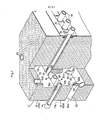
- a tunnel kiln includes a kiln body 11 divided into several sections in a longitudinal direction in which articles to be fired are fed along.
- Each of the sections is composed of an upper kiln body half 12 of an integral construction comprising a ceiling and a pair of upper side wall halves made e.gof refractory brick, and a lower kiln body half 13 of an integral construction comprising a bottom and a pair of lower side wall halves made egof refractory brick.
- a clearance (hereinafter referred to as a feed means passage A) having a vertical dimension large enough to allow feed means 14 such as porcelain rollers having a length greater than the width of the lower kiln body half 13 to be fed along in the direction in which articles to be fired are delivered.
- the lower kiln body half 13 is mounted on a lower transverse beam 18a of a securely assembled frame 18.
- the upper kiln body half 12 is suspended by members 19 from an upper transverse beam 18b of the frame 18, the upper kiln body half 12 being vertically adjustable in height.
- the upper kiln body half 12 has opposite sides connected to brackets 18c of the frame 18 so as to be vertically adjustable in height.
- Delivery means 15, 15 are disposed laterally outside of the kiln body 11 and extend in the longitudinal direction thereof.
- Each of the delivery means 15 is composed of ap endless chain 21, chain sprockets 22, 22 around which the endless chain 21 is trained, a pair of upper and lower chain guide rails 23, 23 mounted on the frame 18, and a chain drive motor 24 operatively coupled to one of the chain sprockets 22.
- the endless chains 21, 21 on both sides are driven synchronously by the motor 24.
- a drive motor or a brake for braking the sprockets 22, 22 disposed on an inlet end E of the tunnel kiln or a brake (not shown) is actuated to tens the chains 21, 21 extending between the inlet end E and outlet end F, so that the endless chains 21, 21 are driven smoothly.
- each of the delivery means 15 has been shown as including the single endless chain 21 disposed outside of the kiln body 11, the present invention is not limited to the illustrated arrangement.
- the endless chain mounting area may be divided into a preheating zone, a firing zone, and a cooling zone, for example, in each of which an endless chain or endless chains may be provided.
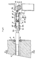
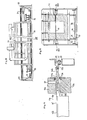
- the chucking means 26 (27) comprises a support shaft 28 (28') having an integral link pin 28a (28'a) of the endless chain 21, a rotatable sleeve 30 (30') mounted by bearings 29, 29 on the support shaft 28 (28'), and a pressing holder 31 (31') threaded in the rotatable sleeve 30 (30').
- the righthand chucking means 26 also includes a planet device 32 comprising a chain sprocket threaded in the rotatable sleeve 30.
- a planet device 32 comprising a chain sprocket threaded in the rotatable sleeve 30.
- One or both of the pressing holders 31, 31' includes a pressing head 3la (31'a) in the form of a resilient body made of heat-resistant rubber or comprising a coil spring.
- the resilient body is laterally expandable and contractable for allowing attachment and detachment of a porcelain feed roller 14, as described later on.
- the pressing head 31a has a cavity 31a' defined therein for taking up longitudinal thermal expansion of the feed roller 14.
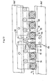
- the feed means 14 comprise cylindrical porcelain rollers detachably mounted on each pair of chucking means 26, 27 of the feed means support mechanism 25. As the delivery means 15, 15 move on, the feed means 14 are moved through the feed means passage A extending in the longitudinal direction of the tunnel kiln. Seal plates 34 are fitted as required over two longitudinally adjacent feed rollers 14, 14 closely to their ends for reducing the amount of ambient flowing into the kiln and preventing heat radiation from leaking outwardly from the kiln through the feed means passaage A. The seal plates 34 are moved with the feed rollers 14 through seal plate passages B (FIG. 4) defined in outer edges of the upper and lower kiln body halves 12, 13.
- the planet device 32 mounted on the rotatable sleeve 30 of the chucking means 26 has been described as comprising a chain sprocket, the planet device is not limited to the chain sprocket, but may comprise a suitable transmission member such as an external spur gear or a frictional roller, not shown.
- the planetary device 32 may not be mounted on the chucking means 26, but may be mounted on the feed roller 14 (preferably near a supported end thereof).
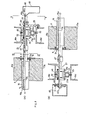
- a sun device 38 for imposing rotative reactive forces to the planet devices 32 for rotating the feed rollers 14 on their own axes comprises a second endless chain 39 trained around the chain sprockets of the planet devices 32, guide rails 40 (FIGS. 3 and 5) attached to the frame 18 for guiding the second endless chain 39, a sprocket 41 around which the second endless chain 39 is trained, a transmission means 42 composed of a gear box 42a and a line shaft 42b for transmitting drive forces to the sprocket 41, and a drive source 43 (FIG. 1) comprising a variable-speed motor.
- the sun device 38 serves to drive the feed means 14 to rotate about their own axes at a desired rotational speed.
- FIG. 8 is illustrative of a feed means support mechanism and a feed roller according to another embodiment.
- the arrangement of FIG. 8 differs from that shown in FIG. 3 in that a support shaft 28" of chucking means 26' is fixedly connected to an attachment 15 1 of delivery means 15 1 , an engagement ring 36 is axially slidably fitted over a holder 31"b of a holder 31" composed of a cylinderial metal body having an axial recess 31"c, the engagement ring 36 being urged inwardly by a spring 37, and an end of a feed roller 14' can automatically be locked in place by allowing a journal 14'a of polygonal cross section on the end of the feed roller 14' to fall downwardly into the recess 31"c in the holder 31"b.
- a sun device 38 for applying rotational reactive forces to a planet device 32 mounted on a rotatable sleeve 30 of the chucking means 26' comprises an endless chain 39 meshing with the planet device 32 and fixed to a guide plate 40 in the longitudinal direction from the inlet end E to the outlet end F (FIG. 1), so that the feed roller 14' can be rotated about its own axis as the delivery means 15' is driven.
- the sun device 38 comprises a rack gear.
- the sun device 38 comprises a web-shaped frictional plate.
- the sun device 38 has a portion parallel to a full length or a portion of the circulating endless chain 21 which constitutes the delivery means 15'.
- the endless chain 21, the planet device 32, and the sun device 38 constitute a differential rotation mechanism which operates on the same principle as that of a differential gear.
- a feed means support mechanism includes righthand chucking means 26 each composed of bearings 44, 44 mounted on link plates 21a, 21a of an endless chain 21, a hollow shaft 45 supported by the bearings 44,44, a guide roller 46 rotatably fitted over the hollow shaft 45 intermediate between the bearings 44,44, a chuck head 47 slidably fitted over the lefthand end of the hollow shaft 45, a compresssion coil spring 49 fitted over the hollow shaft 45 between a retaining ring 48 fitted over the hollow shaft 45 and the chuck head 47, and a rectangular cam plate 50 and a pinion 51 fitted over the hollow shaft 45 for preventing the same from rotating.
- the feed means support mechanism 25 also includes a lefthand chucking means 27 comprising, as shown in FIG. 9(B), bearings 44, 44, a hollow shaft 45', a guide roller 46, and a chuck head 47'on a righthand end of the hollow shaft 45' .
- Roller guide rails 52 are mounted respectively on longitudinal beams 18e, 18e of the frame 18 parallel to the chain guide rails 23 for guiding the guide rollers 46, 46 to keep the hollow shafts 45, 45' of the chucking means 26, 27 in a horizontal position.
- righthand longitudinal beams 18d, 18d' of the frame 18 support cam guide rails 53 for guiding upper and lower sides of the rectangular cam plate 50.
- the feed means support mechanism 25 thus constructed is effective in delivering cylindrical feed rollers 16 detachably mounted on each pair of chucking means 26, 27 in the longitudinal direction of the tunnel kiln along a feed means passage A when the endless chains 21, 21 are driven.
- a seal plate 34 is fitted as required over cores 17 exposed on righthand and lefthand ends of adjacent feed rolleres 16, 16 for preventing hot air from leaking from the kiln through the feed means passage A.
- the seal plates 34 are arranged to pass through seal plate passages B defined in outer edges of upper and lower kiln side wall halves 12a, 13a.
- Each of the feed rollers 16 includes a fibrous layer 16a of silica and alumina covering an outer periphery 17a of the core 17 except its opposite ends the core 17 being in the form of a heat-resistant steel pipe.
- the core 17 is made of Ni-Cr heat- resistaatsteel, and has an outside diameter D of about 25 mm and a wall thickness Tl ranging from 3 to 4 mm.
- the fibrous layer 16a is formed of entangled silica-alumina fibers each having a diameter ranging from 2 to 3 fm and a length ranging from 40 to 250 mm, and has a bulk density ranging from 60 to 200 kg/cm and a thermal conductivity of about 0.18 Kcal/mh°C at 1,000°C. the fibrous layer 16a having a layer thickness T2 ranging from 10 to 15 mm.
- the fibrous layer 16a is mounted by fitting a tubular construction of silica-alumina fibers over the core 17.
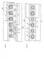
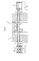
- the tunnel kiln is assembled such that a lower surface 12b of each of the upper side wall halves 12a of the upper kiln body half 12 and an upper surface 13b of each of the lower side wall halves 13a of the lower kiln body half 13 are positioned as closelv to each other as possible so as not to leave large clearances above and below the ends of the feed means 14 moving in the feed means passage A, and such that area of the confronting end surfaces 12b, 13b (the end surface 12b in the illustrated embodiment) has a suction port 54 while the other end surface (13b in the illustrated embodiment) has a hot air outlet port 55.
- the hot air outlet port 55 is open in a position for directing hot air discharged therefrom toward the suction port 54.
- the suction port 54 is composed of a recess 56 extending in the longitudinal direction in the lower end surface 12b of the upper kiln side wall half 12a, with lower ends 57a of inlet pipes 57 opening into the recess 56 at suitable pitches or intervals.
- the inlet pipes 57 have upper ends 57b (FIG. 6) connected to a common pipe 58 coupled to a suction port of a suction unit (not shown) located outside of the kiln body 51 and comprising a turbofan, for example.
- the recess 56 is employed for straightening an air flow to make a uniform suction vacuum on the lower surface 12b of the upper kiln side wall half 12a. Where the inlet pipes 57 are arranged at smaller pitches, the recess 56 may be dispensed with, and the lower ends 57a of the inlet pipes 57 may be directly open at the lower end surface 12b (see FIG.14).
- the hot air outlet port 55 is an upper opening of a slit-shaped hot air passage 59 directed toward the upper end surface 13b of the lower kiln side wall half 13a and extending in the longitudinal direction.
- a compressed-air supply pipe 60 lies in the bottom of the hot air passage 59, and nozzles 61 project from the compressed-air supply pipe 60 at suitable pitches into the hot air passage 59.
- Kiln gas inlet passages 62 having ends 62a opening into a kiln lla have opposite ends 62b opening into the hot air passage 59 in the vicinity of nozzle orifices 61a of the nozzles 61.
- a high-temperature gas in the kiln lla is drawn under dynamic suction from the kiln gas inlet passages 62 and mixed with the air, and the mixture is discharged as a high-temperature air flow (at 400°C, for example ) from the outlet port 55 of the slit-shaped hot air passage 59 in toward the suction port 54.
- the high temperature air flow from the hot air passage 59 forms an air curtain directly thereabove, dividing the feed means passage A into inner and outer sections.
- the slit-shaped hot air passage 59 is employed to disperse the high-temperature air in the longitudinal direction therein for forming a single air film extending from the upper end of the hot air passage 59 and in the longitudinal direction.
- the slit-shaped hot air passage 59 may be dispensed with where the pitches of the nozzles 61 and the pitches of the kiln gas inlet passages 62 are small.
- the slit-shaped hot air passage 59 may be replaced with a column-shaped hot air discharge passage (not shown) defined in the lower kiln side wall half l3a and having an upper end opening at the upper end surface 13b of the lower kiln side wall half 13a, and the nozzle orifices 61a and the ends 62b of the kiln gas inlet passages 62 may open into the column-shaped hot air discharge passage in the vicinity of the bottom thereof.
- the suction port 54 opens at the lower end surface 12b of the upper kiln side wall half 12a, while the hot air outlet port 55 opens at the upper end surface 13b of the lower kiln side wall half 13a.
- the suction port 54 may open at the upper end surface 13b of the lower kiln side wall half 13a, and the hot air outlet port 55 may open at the lower end surface 12b of the upper kiln side wall half 12a.
- FIG. 14 shows an another arrangement in which the suction ports 57a at the lower ends of the inlet pipes 57 open at the lower end surface 12b of the upper kiln side wall half 12a at suitable pitches in the longitudinal directions.
- the suction ports 57a should preferably be open more closely to an outer edge of the lower end surface 12b than to a central portion thereof. This is because the greater distance between the suction aorts 57a and the kiln interior lla, the greater the resistance to the flow of hot air passing from the kiln through the feed means passage A, thus reducing the amount of hot air drawn from the kiln, and preventing any temperature difference between a body 14"b and an arm 14"a of feed means 14" from becoming larger.
- a reduction in the distance between the suction ports 57a and the exterior side of the kiln allows a greater amount of ambient air to be drawn in through the suction ports 57a, thereby cooling the seal plates 34 fitted over the feed means 14 at the ends thereof to prevent the feed means 14 from being overheated.
- the other ends of the inlet pipes 57 are connected through a common pipe (see FIG. 6) or directly to an inlet port of a suction unit comprising a turbofan, for example.
- the feed means 14" shown in FIG. 14 is not cylindrical in shape, but has a body 14"b in the form of a depending plate of porcelain having a vertical cross-sectional shape of T or I.
- the feed means 14" has its end 14"a detachably fixed to an attachment 15'a of delivery means 15'. Therfore, the feed means 14" is not rotatable about its own axis unlike the feed means previously described.
- the tunnel kiln of the present invention also has forced cooling means, indicated at 65 in FIGS. 9 (A) and 9 (B), for cooling the covered feed rollers 16 heated to a high temperature.
- the forced cooling means 65 comprises a cooling gas supply chamber 66 having an open nozzle 66a for ejecting a cooling gas toward axial end openings 45a of hollow shafts 45 constituting the righthand chuck 26, and a suction chamber 67 for drawing a high-temperature gas from axial end openings 45' a of hollow shafts 45' constituting the lefthand chuck 27.
- the suction chamber 67 has a second seal plate passage C for guiding seal plates 68 fitted therein near the axial ends of the adjacent hollow shafts 45' so that no ambient air will be drawn into the suction chamber 67.
- the forced; cooling means 65 is located in the firing zone in which the cores 17 of the covered feed rollers 16 are heated to a higher temperature than is allowable.
- FIG. 13 shows in side elevation an inverter mechanism 69 for turning the covered feed roller 16 180° upside down with its core 17 slightly curved by the heat from the firing zone, while the covered feed roller 16 is moving along a return path outside of the kiln after it has fed an article.
- the inverter mechanism 69 includes a rack 70 mounted on the longitudinal beam 18e' and having an effective length required to rotate the pinion 51 of the chucking means 26 through 180 0 ,.
- Recesses 53a are defined in the cam guide rails 53 for allowing rotation of the cam plates 50.
- FIG. 1 articles (not shown) such as tile bases placed on the feed means 14 (FIG. 2) at the inlet end E are fed along by the feed means 14 which are moved in the feeding direction as the endless chains 21 are driven.
- the articles are fired while they pass through the heated kiln lla and are delivered to the outlet end F.
- the delivery means 15 composed of the endless chains are moved intermittently toward the inlet end E or the outlet end F, and the feed means 14 moved out of the kiln due to intermittent movement of the delivery means 15 are replaced with new ones while the delivery means 15 are at rest.
- the feed means 14 can be replaced in a short period of time. It is important that the delivery means 15 be intermittently fed at a safe speed lower than a speed at which the feed means 14 might be subjected to the danger of becoming broken due to rapid quenching or heating, since the temperature in the high-temperature firing zone is not lowered.
- a drying chamber 71 may be disposed below the kiln body 11 as illustrated in FIGS. 15 and 16.
- the drying chamber 71 is composed of upper and lower thermally insulating wall bodies 72, 73 between which feed means return passages H are vertically sandwiched.
- the feed means 14 can be moved at a desired speed from a position below a. loading device 74 which deposits the articles on the feed means 14 to a position below a discharging device 75 which picks up the dried articles.
- the interior of the drying chamber 71 is heated by an exhaust gas from the kiln body 11.
- the cores 17 are of a high bending strength and a high shock resistance since they comprise heat-resistant pipes, and hence the feed rollers 16 will not be broken under normal use. Therefore, no articles will be dropped in the kiln while they are being fed along, and the production efficiency is increased to a large degree.
- the feed rollers 16 can be renewed simply by replacing the fibrous layer 16a which is inexpensive. Accordingly, the cost of replacement is lowered.
- the tunnel kiln of the invention employs so-called differential rotational mechanisms composed of the planet devices 32 and the sun device 38, so that the feed means 14 will be rotated about their own axes at a low peripheral speed, or the feed means 14", 16 will not be rotated about their own axes at least during a feeding cycle.
- the articles can be fed along without being displaced out of a row, and can be discharged smoothly into an unloader at the outlet end of the tunnel kiln.
Landscapes
- Engineering & Computer Science (AREA)
- Mechanical Engineering (AREA)
- General Engineering & Computer Science (AREA)
- Chemical & Material Sciences (AREA)
- Materials Engineering (AREA)
- Organic Chemistry (AREA)
- Tunnel Furnaces (AREA)
- Muffle Furnaces And Rotary Kilns (AREA)
Applications Claiming Priority (6)
| Application Number | Priority Date | Filing Date | Title |
|---|---|---|---|
| JP59005098A JPS60149874A (ja) | 1984-01-13 | 1984-01-13 | 焼成炉 |
| JP5098/84 | 1984-01-13 | ||
| JP59031100A JPS60174480A (ja) | 1984-02-20 | 1984-02-20 | 焼成炉 |
| JP31100/84 | 1984-02-20 | ||
| JP59212337A JPS6190908A (ja) | 1984-10-09 | 1984-10-09 | 焼成帯用搬送ロ−ラ及び焼成炉 |
| JP212337/84 | 1984-10-09 |
Publications (3)
| Publication Number | Publication Date |
|---|---|
| EP0149531A2 true EP0149531A2 (de) | 1985-07-24 |
| EP0149531A3 EP0149531A3 (en) | 1985-08-21 |
| EP0149531B1 EP0149531B1 (de) | 1987-06-10 |
Family
ID=27276593
Family Applications (1)
| Application Number | Title | Priority Date | Filing Date |
|---|---|---|---|
| EP85300167A Expired EP0149531B1 (de) | 1984-01-13 | 1985-01-10 | Durchlaufofen |
Country Status (5)
| Country | Link |
|---|---|
| US (1) | US4596527A (de) |
| EP (1) | EP0149531B1 (de) |
| KR (1) | KR890002783B1 (de) |
| DE (1) | DE3560245D1 (de) |
| ES (1) | ES538878A0 (de) |
Cited By (4)
| Publication number | Priority date | Publication date | Assignee | Title |
|---|---|---|---|---|
| CN102853655A (zh) * | 2012-06-20 | 2013-01-02 | 张崇云 | 墙砖焙烧隧道窑及焙烧方法 |
| CN104880091A (zh) * | 2015-06-03 | 2015-09-02 | 贵阳白云云雾铝矾土煅烧加工厂 | 节能环保型新式轮窑 |
| CN112229209A (zh) * | 2020-10-26 | 2021-01-15 | 应城市华兴新型环保材料有限公司 | 一种多层网带窑 |
| CN113088740A (zh) * | 2021-04-07 | 2021-07-09 | 北京宏钧新材料技术有限公司 | 一种泡沫铝生产系统及生产方法 |
Families Citing this family (8)
| Publication number | Priority date | Publication date | Assignee | Title |
|---|---|---|---|---|
| US4706651A (en) * | 1986-02-24 | 1987-11-17 | The United States Of America As Represented By The United States Department Of Energy | Solar solids reactor |
| JPH0714353Y2 (ja) * | 1988-07-08 | 1995-04-05 | 中外炉工業株式会社 | ローラハース型熱処理炉 |
| US5205398A (en) * | 1990-07-27 | 1993-04-27 | Eltech Systems Corporation | Insulating roll cover |
| US5848890A (en) * | 1996-12-13 | 1998-12-15 | Mccormick; Edward V. | Furnace product transport system |
| DE102010031245B4 (de) * | 2010-07-12 | 2013-04-11 | Von Ardenne Anlagentechnik Gmbh | Substratbehandlungsanlage |
| CN107619773B (zh) * | 2016-07-14 | 2021-03-09 | 湖南鼎玖能源环境科技股份有限公司 | 一种回转式发酵设备 |
| CN107218811A (zh) * | 2017-05-16 | 2017-09-29 | 李达 | 一种可移动的环保砖窑 |
| CN110953879A (zh) * | 2019-12-27 | 2020-04-03 | 佛山市天禄智能装备科技有限公司 | 一种辊道窑 |
Family Cites Families (10)
| Publication number | Priority date | Publication date | Assignee | Title |
|---|---|---|---|---|
| FR1448278A (fr) * | 1965-06-24 | 1966-08-05 | Saint Gobain | Perfectionnement au transport de feuilles de verre |
| US3867748A (en) * | 1974-03-07 | 1975-02-25 | Libbey Owens Ford Co | Supporting and driving frangible rollers |
| US3934970A (en) * | 1975-02-19 | 1976-01-27 | Mcmaster Harold | Glass tempering system |
| US4034837A (en) * | 1975-11-07 | 1977-07-12 | Hi-Hard Rolls, Inc. | Conveyor roller structure |
| FR2409472A1 (fr) * | 1977-11-19 | 1979-06-15 | Lingl Anlagenbau | Procede et dispositif de montage des rouleaux d'entrainement dans un four tunnel |
| US4332608A (en) * | 1979-05-29 | 1982-06-01 | Rhonehouse Donald E | Chain drive mechanism for equipment for heating and cooling workpieces |
| US4242782A (en) * | 1979-06-08 | 1981-01-06 | Ppg Industries, Inc. | Ceramic conveyor rolls with metal end caps frictionally fixed thereto |
| US4247000A (en) * | 1979-07-16 | 1981-01-27 | Ppg Industries, Inc. | Ceramic conveyor rolls with metal end caps clamped thereto |
| US4352230A (en) * | 1980-01-11 | 1982-10-05 | New Hudson Corporation | Fiber covered roller for high temperature applications |
| US4317667A (en) * | 1981-01-05 | 1982-03-02 | Western Electric Co., Inc. | Method and apparatus for fabricating lightguide preforms |
-
1984
- 1984-12-06 US US06/679,009 patent/US4596527A/en not_active Expired - Fee Related
- 1984-12-20 ES ES538878A patent/ES538878A0/es active Granted
-
1985
- 1985-01-10 KR KR1019850000100A patent/KR890002783B1/ko not_active Expired
- 1985-01-10 EP EP85300167A patent/EP0149531B1/de not_active Expired
- 1985-01-10 DE DE8585300167T patent/DE3560245D1/de not_active Expired
Cited By (4)
| Publication number | Priority date | Publication date | Assignee | Title |
|---|---|---|---|---|
| CN102853655A (zh) * | 2012-06-20 | 2013-01-02 | 张崇云 | 墙砖焙烧隧道窑及焙烧方法 |
| CN104880091A (zh) * | 2015-06-03 | 2015-09-02 | 贵阳白云云雾铝矾土煅烧加工厂 | 节能环保型新式轮窑 |
| CN112229209A (zh) * | 2020-10-26 | 2021-01-15 | 应城市华兴新型环保材料有限公司 | 一种多层网带窑 |
| CN113088740A (zh) * | 2021-04-07 | 2021-07-09 | 北京宏钧新材料技术有限公司 | 一种泡沫铝生产系统及生产方法 |
Also Published As
| Publication number | Publication date |
|---|---|
| US4596527A (en) | 1986-06-24 |
| DE3560245D1 (en) | 1987-07-16 |
| ES8600500A1 (es) | 1985-10-01 |
| ES538878A0 (es) | 1985-10-01 |
| EP0149531B1 (de) | 1987-06-10 |
| EP0149531A3 (en) | 1985-08-21 |
| KR890002783B1 (ko) | 1989-07-28 |
| KR850007876A (ko) | 1985-12-09 |
Similar Documents
| Publication | Publication Date | Title |
|---|---|---|
| EP0149531B1 (de) | Durchlaufofen | |
| US6776008B1 (en) | Method and apparatus for heating glass | |
| JPH04292780A (ja) | ピン加熱炉とその転送装置および転送方法 | |
| JPS5941944B2 (ja) | セラミツクタイルの乾燥及び急速単相焼成を行う自動プラント | |
| US6514340B1 (en) | Lubricant coat forming apparatus | |
| KR100847758B1 (ko) | 얇은 요소의 적어도 한 면위에 유체를 송풍시키는 장치와이와 연계된 송풍 유닛 | |
| US4142304A (en) | Apparatus for gas treatment of articles traversing an enclosure | |
| KR100729429B1 (ko) | 램프 소성장치 | |
| JPH0582450B2 (de) | ||
| US4983201A (en) | Method and apparatus in a glass sheet bending furnace for preventing the deflection of mould wagon bearing rails | |
| CS209875B2 (en) | Device for the heat processing of generated particularly porous objects | |
| US5149352A (en) | Method of and system for bending sheet glass | |
| US2548683A (en) | Annealing furnace and conveyer | |
| KR200318436Y1 (ko) | 피디피 페이스트막 소성용 연속소성로 | |
| US2317009A (en) | Apparatus for subjecting cylindrical members to heat treatment | |
| JPS6190908A (ja) | 焼成帯用搬送ロ−ラ及び焼成炉 | |
| US3223252A (en) | Treatment of glass | |
| IT8367093A1 (it) | Apparecchio e procedimento per la tempra di lastre di vetro | |
| JPS61122484A (ja) | 2段焼成炉 | |
| KR100308082B1 (ko) | 튜브 성형장치 및 방법 | |
| RU1772554C (ru) | Установка дл сушки труб с внутренним покрытием | |
| JP2003014375A (ja) | 被焼成板の連続式焼成炉装置 | |
| US4597735A (en) | High-efficiency porcelain enameling furnace | |
| JPS6228384B2 (de) | ||
| JPH047506Y2 (de) |
Legal Events
| Date | Code | Title | Description |
|---|---|---|---|
| PUAI | Public reference made under article 153(3) epc to a published international application that has entered the european phase |
Free format text: ORIGINAL CODE: 0009012 |
|
| PUAL | Search report despatched |
Free format text: ORIGINAL CODE: 0009013 |
|
| AK | Designated contracting states |
Designated state(s): DE FR GB IT |
|
| AK | Designated contracting states |
Designated state(s): DE FR GB IT |
|
| 17P | Request for examination filed |
Effective date: 19851022 |
|
| 17Q | First examination report despatched |
Effective date: 19860826 |
|
| RAP1 | Party data changed (applicant data changed or rights of an application transferred) |
Owner name: INAX CORPORATION |
|
| GRAA | (expected) grant |
Free format text: ORIGINAL CODE: 0009210 |
|
| AK | Designated contracting states |
Kind code of ref document: B1 Designated state(s): DE FR GB IT |
|
| REF | Corresponds to: |
Ref document number: 3560245 Country of ref document: DE Date of ref document: 19870716 |
|
| ITF | It: translation for a ep patent filed | ||
| ET | Fr: translation filed | ||
| PLBE | No opposition filed within time limit |
Free format text: ORIGINAL CODE: 0009261 |
|
| STAA | Information on the status of an ep patent application or granted ep patent |
Free format text: STATUS: NO OPPOSITION FILED WITHIN TIME LIMIT |
|
| 26N | No opposition filed | ||
| ITTA | It: last paid annual fee | ||
| PGFP | Annual fee paid to national office [announced via postgrant information from national office to epo] |
Ref country code: GB Payment date: 19930104 Year of fee payment: 9 |
|
| PGFP | Annual fee paid to national office [announced via postgrant information from national office to epo] |
Ref country code: FR Payment date: 19930111 Year of fee payment: 9 |
|
| PGFP | Annual fee paid to national office [announced via postgrant information from national office to epo] |
Ref country code: DE Payment date: 19930115 Year of fee payment: 9 |
|
| PG25 | Lapsed in a contracting state [announced via postgrant information from national office to epo] |
Ref country code: GB Effective date: 19940110 |
|
| GBPC | Gb: european patent ceased through non-payment of renewal fee |
Effective date: 19940110 |
|
| PG25 | Lapsed in a contracting state [announced via postgrant information from national office to epo] |
Ref country code: FR Effective date: 19940930 |
|
| PG25 | Lapsed in a contracting state [announced via postgrant information from national office to epo] |
Ref country code: DE Effective date: 19941001 |
|
| REG | Reference to a national code |
Ref country code: FR Ref legal event code: ST |