EP0149436A2 - Vorrichtung zum Beschicken und Verdichten des Mülls im Inneren eines Müllfahrzeugtanks - Google Patents
Vorrichtung zum Beschicken und Verdichten des Mülls im Inneren eines Müllfahrzeugtanks Download PDFInfo
- Publication number
- EP0149436A2 EP0149436A2 EP84830348A EP84830348A EP0149436A2 EP 0149436 A2 EP0149436 A2 EP 0149436A2 EP 84830348 A EP84830348 A EP 84830348A EP 84830348 A EP84830348 A EP 84830348A EP 0149436 A2 EP0149436 A2 EP 0149436A2
- Authority
- EP
- European Patent Office
- Prior art keywords
- shovel
- refuse
- shovels
- loading
- hinge
- Prior art date
- Legal status (The legal status is an assumption and is not a legal conclusion. Google has not performed a legal analysis and makes no representation as to the accuracy of the status listed.)
- Granted
Links
Images


Classifications
-
- B—PERFORMING OPERATIONS; TRANSPORTING
- B65—CONVEYING; PACKING; STORING; HANDLING THIN OR FILAMENTARY MATERIAL
- B65F—GATHERING OR REMOVAL OF DOMESTIC OR LIKE REFUSE
- B65F3/00—Vehicles particularly adapted for collecting refuse
- B65F3/14—Vehicles particularly adapted for collecting refuse with devices for charging, distributing or compressing refuse in the interior of the tank of a refuse vehicle
- B65F3/20—Vehicles particularly adapted for collecting refuse with devices for charging, distributing or compressing refuse in the interior of the tank of a refuse vehicle with charging pistons, plates, or the like
Definitions
- This invention relates to a device for loading refuse into the body of a refuse collecting vehicle and for compacting refuse in said vehicle body, the device including a pair of shovels pivotally connected to one another and individually driven by means, preferably of the hydraulic type, which cause the shovels to perform such movements as to permit refuse that is being fed to a refuse receiving trough, to be picked up therefrom, transferred to a box-like body of the vehicle and compacted therein.
- Refuse collecting vehicles usually include a loading body or chamber that is carried by the structure of the vehicle and is provided at the rear with a loading opening or. inlet through which waste matter is fed to a receiving trough to be then pushed by suitable means to the interior of said chamber.
- a movable gate that is designed to form a front end vail for the chamber opposite to said inlet opening therefor, the movable gate being caused to move rearwardly during unloading in order to allow refuse to be discharged from the rear side of the chamber after the unit comprising the receiving trough and the loading and compacting device have been raised.
- a vide-spread device comprises a pair of swingable shovels, one of which is intended for bringing refuse up from the bottom of a receiving trough, while the other, which is to accurately operate in step with the first named shovel, is designed to push the raised refuse to the interior of a collecting box.
- the shove arrangement thereof does not allow a comparatively bulky refuse, such as a waste electro- domestic appliance, entering the collecting chamber.
- Another prior known device makes use of a receiving trough provided with a bottom semi-circular in shape, and a shovel comprising and arm having a length equal to a radius of said bottom, the arm being so pivoted at a central part thereof as to be swingable through 180 0 to cause refuse collected during the successive strokes to be pushed to the interior of the collecting chamber alternatively on one side and the other of the swinging axis of the shovel.
- a complicate kinematics is required for displacing the shovel and the problem again arises that bulky refuse is not able to be loaded due to the rear opening of the collecting chamber being for less than half its effective capacity available for use.
- the quantity of refuse that may be fed to the collecting chamber during each single loading step is small.
- vhich device is so constructed as to make the rear opening of a vehicle collecting body thoroughly available for use, that is to an extent that permits refuse of considerable bulky nature, such as waste pieces of electro- domestic appliance and the like, to be easily admitted thereto.
- the device of the invention considerably increases the working rate, as compared to devices of a technique known, since it is able, .in a single step, to load into a collecting chamber the entire contents of the receiving trough, the curvilinear-shaped bottom of which is designed to increase its capacity.
- this device included a pair of sholvels that extend throughout the width of a loading container and are hingedly connected to one another, the upper shovel also being hinged to a fixed structure of a vehicle in such a manner that said upper shovel is able to swing about the axis of said latter hinge point, while the lover shovel, which preferably is of substantial greater size than the upper-one is, can both swing about the hinge axis pivotally connecting the two shovels together, and perform translating motions that are due to the displacement of said latter hinge axis as a result of the swinging movement of the upper shovel, means being provided for driving the two shovels into separate and combined motions in order to permit the lower shovel to go down the receiving trough and to follow the curved shape of the bottom thereof to transfer contents of the receiving trough to the loading chamber or container.
- Said means for driving the two shovels into motion are preferably hydraulic jacks that are arranged in pairs- one pair jacks for each shovel-near the side walls of a vehicle, that are acting substantially on the center lines of the shovels, and that react upon the fixed structure of the concerned vehicle.
- an hydraulic motor could be substituted for the pair of hydraulic jacks to impart swinging motion to the upper shovel.
- a movable framework 3 in which the loading and compacting device according to the invention is housed, the device being generally indicated by the reference numeral 4 and having a refuse receiving space or trough 5 carried in a lover part thereof.
- the framework 3 is a movable in that, vhen refuse loading is completed and in order to allow for the body 2 being emptied, the framework 3 is raised by causing it to rotate about a suspension axis that is arranged in a upper part of the body 2 according to a well known technique. During refuse loading and compacting operations, however, the framework 3 is rigidly locked with the body or chamber 2, that is to say the fixed structure of the vehicle. Thus, it is to be intended that the expression “movable framework” could also be replaced by "fixed structure of the vehicle” throughout the following description.
- the device according to the invention essentially comprises a pair of shovels 6 and 7 extending over the width of the chamber 2 and being hinged to one another by means of a hinge 8.
- the upper shovel 6 has its other end 9 hinged to the fixed structure of the vehicle in such a manner that said shovel 6, upon being appropriately driven, only can swing about the axis of hinge 9, by the hinge 8 being displaced over. an arc of a circle.
- the lover shovel 7 has its other end in a free condition and is usually substantially greater in size than is the upper shovel 6, the operation of loading refuse into the chamber 2 and compacting it therein being almost entirely accomplished by said shovel 7.
- the shovel 7 can swing about the axis of hinge 8 pivotally interconnecting the two shovels, and it is displaceable in a fixed relationship with the axis of said hinge 8.
- the shovels 6 and 7 are driven into motion under action of pairs of hydraulic jacks 10 and 11 respectively, which act through hinge means 12 and 13 respectively, substantially upon the center lines of shovels 6. and 7 and which react, also through hinged connections 14 and 15 respectively, upon a rear end portion of the fixed structure of the vehicle.
- the jacks 10, 11 of each pair thereof preferably are arranged in proximity to the side walls of the vehicle so as to allow for easy movements of the shovels and prevent effective loading space from being obstructed.
- the curvilinear bottom 5' of the receiving trough 5 should be shaped so as to through l y match the path decribed by the free end 7' of shovel 7 during the loading step, which path is imposed through the kinematics by which the two shovels 6 and 7 are acted upon.
- the loading and compacting device operates on a continuous basis; in that refuse may be admitted to the receiving trough 5 from a rear inlet opening 16 in the movable framework 3 at any position occupied by the device 4 during a working cycle.
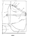
- Figure 2 shows the device when at the end of a loading and compacting cycle, with the upper shovel 6 being inclined slight upwardly and the lower shovel 7 in a right vertical position.
- the oil fluid in the pair of jacks 11 driving the shovel 7 is pumped out to completely retract the associated piston rode back to the position in figure 3 thereby causing the shovel 7 to perform a swinging motion about the axis of hinge 8 that is remained stationary during this step.
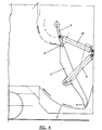
- the oil fluid in the pair of jacks 10 driving the upper shovel 6 is pumped out whereby this shovel 6 is . caused to perform a rotation about the stationary hinge 9 to bring the device to the position shown in figure 4.
- the figure 4 position is the starting position for the loading and compacting step.
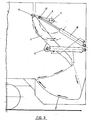
- both the pairs of jacks 10 and 11 are charged to simultaneously produce a clockwise rotation of shovel 6 and a motion of shovel 7 which is the effective compacting shovel this motion being such that the free end 7' of shovel 7 will describe a path that follows so the curvilinear-shaped bottom 5' of the receiving trough 5 as to cause refuse contained therein to be pushed to the interior of the container 2.
- Figure 5 shows the device at an intermediate position thereof during the loading step, while figure 2 shows its position at the end of the loading and compacting cycle.
- the pair of jacks 10 driving the shovel 6 complete their strocke shortly before the end of stroke of the pair of jacks 11 drawing the compacting shovel 7 so that this shovel 7, being further acted upon by the associated jacks 11, may swing about the axis of hinge 8 to give the refuse a final compaction.
- movements of shovels 6 and 7 could be obtained by means other than the described hydraulic jacks 10 and 11, so long as the end 7' of shovel 7 is enabled to follow the curvilinear bottom 5' of the receiving trough 5.
- a hydraulic motor could be substituted for the pair of jacks 10 driving the shovel 6, which motor would cause the shovel 6 to perform a rotation about the axis of hinge 9 in the same manner as described herein before.
Landscapes
- Engineering & Computer Science (AREA)
- Mechanical Engineering (AREA)
- Refuse-Collection Vehicles (AREA)
- Refuse Collection And Transfer (AREA)
- Refuse Receptacles (AREA)
Priority Applications (1)
| Application Number | Priority Date | Filing Date | Title |
|---|---|---|---|
| AT84830348T ATE48113T1 (de) | 1984-01-06 | 1984-12-19 | Vorrichtung zum beschicken und verdichten des muells im inneren eines muellfahrzeugtanks. |
Applications Claiming Priority (2)
| Application Number | Priority Date | Filing Date | Title |
|---|---|---|---|
| IT1905284 | 1984-01-06 | ||
| IT19052/84A IT1172971B (it) | 1984-01-06 | 1984-01-06 | Dispositivo per il carico e la compattazione di rifiuti solidi nei cassoni dei veicoli di raccolta |
Publications (3)
| Publication Number | Publication Date |
|---|---|
| EP0149436A2 true EP0149436A2 (de) | 1985-07-24 |
| EP0149436A3 EP0149436A3 (en) | 1986-10-08 |
| EP0149436B1 EP0149436B1 (de) | 1989-11-23 |
Family
ID=11154140
Family Applications (1)
| Application Number | Title | Priority Date | Filing Date |
|---|---|---|---|
| EP84830348A Expired EP0149436B1 (de) | 1984-01-06 | 1984-12-19 | Vorrichtung zum Beschicken und Verdichten des Mülls im Inneren eines Müllfahrzeugtanks |
Country Status (8)
| Country | Link |
|---|---|
| US (1) | US4786228A (de) |
| EP (1) | EP0149436B1 (de) |
| AT (1) | ATE48113T1 (de) |
| CA (1) | CA1252068A (de) |
| DE (1) | DE3480537D1 (de) |
| ES (1) | ES539361A0 (de) |
| GR (1) | GR82603B (de) |
| IT (1) | IT1172971B (de) |
Cited By (2)
| Publication number | Priority date | Publication date | Assignee | Title |
|---|---|---|---|---|
| EP1028072A1 (de) | 1999-02-12 | 2000-08-16 | Haller Umweltsysteme GmbH & Co. | Belade- und Verdichtungseinrichtung für den Sammelbehälter eines Abfallsammelfahrzeugs |
| KR100805809B1 (ko) * | 2005-08-24 | 2008-02-21 | 가부시키가이샤 엔.티.티.도코모 | 송신 전력 제어 방법 및 이동 통신 시스템 |
Families Citing this family (11)
| Publication number | Priority date | Publication date | Assignee | Title |
|---|---|---|---|---|
| US5123801A (en) * | 1990-09-27 | 1992-06-23 | Daniel Harold W O | Refuse collecting vehicle |
| US5478188A (en) * | 1994-05-05 | 1995-12-26 | The Heil Company | Programmable controlled tailgate compaction mechanism for rear-loading refuse vehicles |
| FI5550U1 (fi) * | 2001-04-19 | 2002-10-17 | Bent Eriksen Handelsselskab Ap | Paperijätteiden tiivistämiseen tarkoitettu säiliö |
| US20080105761A1 (en) * | 2004-08-25 | 2008-05-08 | Blast N Clean Llc | Interior and exterior cleaning of waste carts and containers |
| US20080105474A1 (en) * | 2004-08-25 | 2008-05-08 | Blast N Clean Llc | Cart and container cleaning system with heated fluid |
| US20080110476A1 (en) * | 2004-08-25 | 2008-05-15 | Blast N Clean Llc | Container cleaning system using nozzles |
| US9102466B2 (en) | 2012-01-01 | 2015-08-11 | Haul-All Equipment Ltd. | Waste collection vehicle with bucket drive mechanism |
| JP6418933B2 (ja) * | 2014-12-16 | 2018-11-07 | 極東開発工業株式会社 | 塵芥収集車 |
| JP6418939B2 (ja) * | 2014-12-25 | 2018-11-07 | 極東開発工業株式会社 | 塵芥収集車 |
| CA3154028A1 (en) | 2019-10-07 | 2021-04-15 | Eric BOIVIN | System for lifting and tipping a bin containing solid waste materials in a container body and container assembly having the same |
| WO2021090337A1 (en) * | 2019-11-10 | 2021-05-14 | Indico Motors Pvt. Ltd. | Hopper tipper with shovel fitment |
Family Cites Families (7)
| Publication number | Priority date | Publication date | Assignee | Title |
|---|---|---|---|---|
| LU38556A1 (de) * | 1959-04-28 | |||
| JPS5243289B2 (de) * | 1973-02-19 | 1977-10-29 | ||
| US3889828A (en) * | 1973-09-27 | 1975-06-17 | Sargent Industries | Noise reduction apparatus and method |
| US3874529A (en) * | 1974-05-31 | 1975-04-01 | Leach Corp | Refuse loading apparatus |
| US4050594A (en) * | 1975-10-20 | 1977-09-27 | Leach Company | Refuse loading apparatus |
| NL7811772A (nl) * | 1978-12-01 | 1980-06-03 | Vandekerckhove Constr | Verbeterde laadinrichting voor vuilniswagens. |
| US4460307A (en) * | 1982-08-02 | 1984-07-17 | Dempster Systems Inc. | Refuse collection vehicle compaction apparatus |
-
1984
- 1984-01-06 IT IT19052/84A patent/IT1172971B/it active
- 1984-12-19 AT AT84830348T patent/ATE48113T1/de not_active IP Right Cessation
- 1984-12-19 EP EP84830348A patent/EP0149436B1/de not_active Expired
- 1984-12-19 DE DE8484830348T patent/DE3480537D1/de not_active Expired
- 1984-12-28 GR GR82603A patent/GR82603B/el unknown
-
1985
- 1985-01-04 CA CA000471527A patent/CA1252068A/en not_active Expired
- 1985-01-04 ES ES539361A patent/ES539361A0/es active Granted
-
1986
- 1986-08-15 US US06/898,812 patent/US4786228A/en not_active Expired - Fee Related
Cited By (3)
| Publication number | Priority date | Publication date | Assignee | Title |
|---|---|---|---|---|
| EP1028072A1 (de) | 1999-02-12 | 2000-08-16 | Haller Umweltsysteme GmbH & Co. | Belade- und Verdichtungseinrichtung für den Sammelbehälter eines Abfallsammelfahrzeugs |
| DE19905986C1 (de) * | 1999-02-12 | 2001-01-04 | Haller Umweltsysteme Gmbh & Co | Belade- und Verdichtunseinrichtung für den Sammelbehälter eines Abfallsammelfahrzeugs sowie Arbeitsverfahren dafür |
| KR100805809B1 (ko) * | 2005-08-24 | 2008-02-21 | 가부시키가이샤 엔.티.티.도코모 | 송신 전력 제어 방법 및 이동 통신 시스템 |
Also Published As
| Publication number | Publication date |
|---|---|
| CA1252068A (en) | 1989-04-04 |
| GR82603B (en) | 1985-03-08 |
| EP0149436A3 (en) | 1986-10-08 |
| US4786228A (en) | 1988-11-22 |
| DE3480537D1 (en) | 1989-12-28 |
| EP0149436B1 (de) | 1989-11-23 |
| ES8601060A1 (es) | 1985-11-01 |
| IT8419052A0 (it) | 1984-01-06 |
| ATE48113T1 (de) | 1989-12-15 |
| IT1172971B (it) | 1987-06-18 |
| ES539361A0 (es) | 1985-11-01 |
Similar Documents
| Publication | Publication Date | Title |
|---|---|---|
| EP0149436A2 (de) | Vorrichtung zum Beschicken und Verdichten des Mülls im Inneren eines Müllfahrzeugtanks | |
| US4877366A (en) | Refuse vehicle | |
| US4096956A (en) | Refuse vehicle | |
| US4050594A (en) | Refuse loading apparatus | |
| CA2093164A1 (en) | Automated carry can and method of use | |
| US4113120A (en) | Container handling and transporting apparatus | |
| US4316695A (en) | Garbage compaction truck | |
| US4460307A (en) | Refuse collection vehicle compaction apparatus | |
| WO1999019237A1 (en) | Refuse collection vehicle | |
| US7086818B2 (en) | Full-eject automated side/front loading collection vehicle | |
| SU1012795A3 (ru) | Устройство дл загрузки мусора в кузов мусоровоза | |
| CN2547690Y (zh) | 自装卸式垃圾车 | |
| US4298306A (en) | Apparatus for loading solid material into a container | |
| US6402453B1 (en) | Side dump body including a material compaction assembly | |
| US4173423A (en) | Trash bin loader and compactor for trash collecting vehicles | |
| US2793769A (en) | Refuse truck with load packing means | |
| US3662908A (en) | Vehicle loader | |
| GB2138386A (en) | Refuse collection vehicle | |
| US2879906A (en) | Refuse loader | |
| US3779409A (en) | Container dumping mechanism for a rear loader refuse vehicle | |
| EP0659659A1 (de) | Müllpresse für ein Müllsammelfahrzeug | |
| GB1601846A (en) | Refuse collection device | |
| GB2167036A (en) | Refuse loading apparatus | |
| US3632000A (en) | Vehicle for collecting refuse and the like | |
| US6478527B2 (en) | Loading and compacting device for the trash container of a trash-collecting vehicle and a working method therefor |
Legal Events
| Date | Code | Title | Description |
|---|---|---|---|
| PUAI | Public reference made under article 153(3) epc to a published international application that has entered the european phase |
Free format text: ORIGINAL CODE: 0009012 |
|
| AK | Designated contracting states |
Designated state(s): AT BE CH DE FR GB LI LU NL SE |
|
| PUAL | Search report despatched |
Free format text: ORIGINAL CODE: 0009013 |
|
| AK | Designated contracting states |
Kind code of ref document: A3 Designated state(s): AT BE CH DE FR GB LI LU NL SE |
|
| 17P | Request for examination filed |
Effective date: 19870327 |
|
| 17Q | First examination report despatched |
Effective date: 19880324 |
|
| GRAA | (expected) grant |
Free format text: ORIGINAL CODE: 0009210 |
|
| AK | Designated contracting states |
Kind code of ref document: B1 Designated state(s): AT BE CH DE FR GB LI LU NL SE |
|
| REF | Corresponds to: |
Ref document number: 48113 Country of ref document: AT Date of ref document: 19891215 Kind code of ref document: T |
|
| ET | Fr: translation filed | ||
| REF | Corresponds to: |
Ref document number: 3480537 Country of ref document: DE Date of ref document: 19891228 |
|
| PLBE | No opposition filed within time limit |
Free format text: ORIGINAL CODE: 0009261 |
|
| STAA | Information on the status of an ep patent application or granted ep patent |
Free format text: STATUS: NO OPPOSITION FILED WITHIN TIME LIMIT |
|
| 26N | No opposition filed | ||
| EPTA | Lu: last paid annual fee | ||
| PGFP | Annual fee paid to national office [announced via postgrant information from national office to epo] |
Ref country code: DE Payment date: 19941229 Year of fee payment: 11 Ref country code: CH Payment date: 19941229 Year of fee payment: 11 |
|
| PGFP | Annual fee paid to national office [announced via postgrant information from national office to epo] |
Ref country code: SE Payment date: 19941230 Year of fee payment: 11 Ref country code: FR Payment date: 19941230 Year of fee payment: 11 |
|
| PGFP | Annual fee paid to national office [announced via postgrant information from national office to epo] |
Ref country code: NL Payment date: 19941231 Year of fee payment: 11 |
|
| PGFP | Annual fee paid to national office [announced via postgrant information from national office to epo] |
Ref country code: LU Payment date: 19950101 Year of fee payment: 12 |
|
| PGFP | Annual fee paid to national office [announced via postgrant information from national office to epo] |
Ref country code: BE Payment date: 19950111 Year of fee payment: 11 |
|
| PGFP | Annual fee paid to national office [announced via postgrant information from national office to epo] |
Ref country code: GB Payment date: 19950118 Year of fee payment: 11 |
|
| EAL | Se: european patent in force in sweden |
Ref document number: 84830348.3 |
|
| PG25 | Lapsed in a contracting state [announced via postgrant information from national office to epo] |
Ref country code: GB Effective date: 19951219 |
|
| PG25 | Lapsed in a contracting state [announced via postgrant information from national office to epo] |
Ref country code: SE Effective date: 19951220 |
|
| PGFP | Annual fee paid to national office [announced via postgrant information from national office to epo] |
Ref country code: AT Payment date: 19951221 Year of fee payment: 12 |
|
| PG25 | Lapsed in a contracting state [announced via postgrant information from national office to epo] |
Ref country code: LI Effective date: 19951231 Ref country code: CH Effective date: 19951231 Ref country code: BE Effective date: 19951231 |
|
| BERE | Be: lapsed |
Owner name: F.LLI MAZZOCCHIA S.R.L. OFFICICINE MECCANICHE Effective date: 19951231 |
|
| PG25 | Lapsed in a contracting state [announced via postgrant information from national office to epo] |
Ref country code: NL Effective date: 19960701 |
|
| GBPC | Gb: european patent ceased through non-payment of renewal fee |
Effective date: 19951219 |
|
| REG | Reference to a national code |
Ref country code: CH Ref legal event code: PL |
|
| PG25 | Lapsed in a contracting state [announced via postgrant information from national office to epo] |
Ref country code: FR Effective date: 19960830 |
|
| NLV4 | Nl: lapsed or anulled due to non-payment of the annual fee |
Effective date: 19960701 |
|
| PG25 | Lapsed in a contracting state [announced via postgrant information from national office to epo] |
Ref country code: DE Effective date: 19960903 |
|
| REG | Reference to a national code |
Ref country code: FR Ref legal event code: ST |
|
| PG25 | Lapsed in a contracting state [announced via postgrant information from national office to epo] |
Ref country code: LU Free format text: LAPSE BECAUSE OF NON-PAYMENT OF DUE FEES Effective date: 19961219 Ref country code: AT Effective date: 19961219 |