EP0148812A2 - In geschlossenem Zustand koplanares Schiebefenster - Google Patents
In geschlossenem Zustand koplanares Schiebefenster Download PDFInfo
- Publication number
- EP0148812A2 EP0148812A2 EP85850009A EP85850009A EP0148812A2 EP 0148812 A2 EP0148812 A2 EP 0148812A2 EP 85850009 A EP85850009 A EP 85850009A EP 85850009 A EP85850009 A EP 85850009A EP 0148812 A2 EP0148812 A2 EP 0148812A2
- Authority
- EP
- European Patent Office
- Prior art keywords
- window
- sashes
- profile
- frame
- profiles
- Prior art date
- Legal status (The legal status is an assumption and is not a legal conclusion. Google has not performed a legal analysis and makes no representation as to the accuracy of the status listed.)
- Granted
Links
Images
Classifications
-
- E—FIXED CONSTRUCTIONS
- E06—DOORS, WINDOWS, SHUTTERS, OR ROLLER BLINDS IN GENERAL; LADDERS
- E06B—FIXED OR MOVABLE CLOSURES FOR OPENINGS IN BUILDINGS, VEHICLES, FENCES OR LIKE ENCLOSURES IN GENERAL, e.g. DOORS, WINDOWS, BLINDS, GATES
- E06B3/00—Window sashes, door leaves, or like elements for closing wall or like openings; Layout of fixed or moving closures, e.g. windows in wall or like openings; Features of rigidly-mounted outer frames relating to the mounting of wing frames
- E06B3/32—Arrangements of wings characterised by the manner of movement; Arrangements of movable wings in openings; Features of wings or frames relating solely to the manner of movement of the wing
- E06B3/34—Arrangements of wings characterised by the manner of movement; Arrangements of movable wings in openings; Features of wings or frames relating solely to the manner of movement of the wing with only one kind of movement
- E06B3/42—Sliding wings; Details of frames with respect to guiding
- E06B3/46—Horizontally-sliding wings
- E06B3/4609—Horizontally-sliding wings for windows
- E06B3/4627—Horizontally-sliding wings for windows with the sliding wing flush closing or moving a considerable distance towards the opening when closing
Definitions
- the present invention refers to a coplanar closure sliding window which has been designed to carry out two main objectives, viz.:
- a metal window such as aluminium sliding windows
- a metal window must be constructed using six profiles having different structures.
- One profile is used to construct the side section of the window frame, whilst another type of profile defines the upper section, the frame structure being completed with another type of profile defining the lower section.
- another three different types of profiles are necessary, since one of them constitutes the vertical section of the central sash, another type constitutes the vertical sections of the sides of the window sash, and a third type constitutes the horizontal sections which close the rectangular structure of each window.
- Utility Model 274,043 With the idea of overcoming this disadvantage, the structure described in Utility Model 274,043 was registered, which consists of an improved sliding window having a sealed closure.
- This window constitutes the most up-to-date embodiment and, in principle, improves all the windows of the mentioned registrations, wherefore the merits of the present invention will be discussed subsequently based on the structure thereof.
- a window constructed in accordance with the structure of the present invention is only and exclusively made from the functional association of three different types of profiles, which clearly implies a substantial reduction in the production costs of a window.
- the entire window frame is constructed using a single profile, all the vertical sections of the window sashes being formed of another different profile having an exceptional cesign, whereas the horizontal sections of the sashes are constructed from a third type of profile.
- the window of this invention has other important characteristics of design which will be described.
- the assembly was closed by placing in the window a three-point closure which actuated the corresponding sash fasteners.
- the window of the present invention discards a high number of all these accessories, presenting a dual interest since apart from not having to purchase them, they do not have to be incorporated when constructing the window.
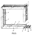
- the profile determining the shape of the window frame is made with an intrinsic and studied design which not only permits the entire configuration of the frame with a single profile, but its different sections carry out interesting services, referring to both the vertical sections of the frame and the horizontal sections thereof.
- the window frame has a U-shaped configuration and its central section has a straight section, the sliding sashes could slide along this central section easily, whilst facilitating Eachining of the frame itself.
- the profile of utility model 274,043 presented at its central zone two concave grooves along which the window rolled.
- a large amount of dust and dirt accumulates in such grooves, which apart from preventing the correct sliding of the sliding sashes, acted as an emery deteriorating the surface of the horizontal sections of the frame.
- the profile constituting the frame has two longitudinal wings disposed at its central section, which will act as guides for the sliding sashes, referring to the horizontal sections of the frame.
- one of these guides plays the important role of a deflecting device of the window sashes, leading them to their closed position.
- a gutter rail in the lower horizontal section thereof since this will be integrated in the structure itself of the window frame, precisely due to this structure with which it has been provided.
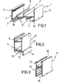
- the coplanar closure sliding window of the present invention is comprised of only three profiles, differing from one another.
- the profile 1 represented in figure 1 constitutes the entire window frame. As can be seen, this profile has a predominantly U-shaped configuration, its central section 2 being completely flat, and at a centered zone thereof there is a longitudinal flange 3 normal to its plane.
- this central section 2 does not join the two wings 4 and 5 of the profile, but ends in an inclined wing 6 which projects in an inclined position from a point lower than this central section 2, ending at a short horizontal sector 7 to be joined to the wing 4.
- this inclined wing 6 will play an important role in the correct functioning offered by this sliding window, furthermore forcing the sashes to exert a pressure on a perimetral weatherstrip placed in the rail 4' of the wing 4.
- Figure 2 illustrates the configuration of the profile 8 determining the vertical sections of the window sashes.
- This profile 8 has a zone 9 which will be coupled to a profile determining the horizontal sections of the window sashes.
- the most characteristic pert of this profile 8 resides in its face or front 10 which has a flat zone 11 and a dovetailed rail 12 which, at the outer face 13 of this profile 8 projects into a stepped projectionl4.
- This configuration is highly important at the time of coupling or closing the window between the two sashes, as well as at the time of producing displacement thereof to the operative closure position, as will subsequently be described.
- This dovetailed recess 12 will be provided with a tight seal 15 pressure-coupled in the recess and having a lip 16 which will be housed beneath the projection 14.
- the horizontal sections of the window sashes are constructed with the profile 17 illustrated in .figure 3.
- This profile has an upper zone 18 in which will be housed the edges of the window pane and a lower zone 19 in which will be housed the roller supports 20 of the window itself, as well as complementary cleaning or sweeping elements of the rolling, adjustment and sealing zones of the wings thereof.
- the face 21 which will be located at the outer zone of the window, incorporates a widening 22 whereby the difference in width between profiles will be compensated when this profile 17 is coupled to the profile 18, to form a window sash.
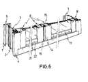
- a window is obtained whose exterior appearance can be seen in figure 6 in which not only the perfect sealed closure effected by this window is illustrated, but also the appearance proportioned ty it, since the appearance offered by the two central vertical sections of the window is completely symmetrical, that is the amplitude of each of these sections 8 is practically the same, differing from other embodiments in which the system or configuration adopted prevented this appearance from being obtained.
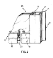
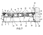
- the inclined wings 6 of the frame 1 press a rubber piece 12' fixed to the cut outs 12 and supported on the stepping 14 of the corresponding profile 8, which causes a displacement of the sash to be placed under pressure against the perimetral weatherstrip of the wing 4 of the frame, thereby obtaining a sealed closure.
- the inclined wings 6 act as a bolt or locking element.
- Closure is complemented by the pressure exerted by the set of wedge and counter-wedge 23 and 24 secured to a zone of the frame and at the lower part of the fixed sash respectively, this being blocked.
- this figure 7 illustrates how the closure obtained is entirely sealed and, besides, utilizing the elastic characteristics of the rubber seals 15, the closure is completely silent, thereby obtaining a determined pressure characteristic in the closure obtained, upon actuating the closure and opening control 26.
- this entire structure proportions a completely sealed, coplanar closure sliding window which improves a series of characteristics of already known windows of this type, since apart from eliminating the functional disadvantages represented by them, inasmuch as they proportion a completely correct use and operative functioning, it eliminates the incorporation of a high number of component parts, with the repercussions this detail have on the cost of the finished product, to which must be added the saving in hand labour also involved therein.
- the square joining between the metal profiles of the frame 1 can also take place by means of the pieces 30, whereby a watertight closure is obtained.
- This prismatic piece 30 is preferably obtained by plastic injection, in which a part of its geometry fits by sliding into the outer part of the profile comprising the window frame, the mentioned piece having another part of its geometry emerging from the frame profile and which is capable of entering tightlg in the remaining zone of the profile of the frame determining the other wing of the square.
- the joining between both profiles is secured by screws passing through the holes 31 provided in the joining element 20 and placed in correspondence with the self-tapping screws 31 of the profile of the frame 1.
- the profile 32 illustrates the guide profile for the blind, being coupled, as illustrated in this figure, by sliding on the profile 1 of the frame, when a curvilinear end swelling of this profile 32 is inserted in the corresponding self-tapping screw 31 of the profile 1, simultaneous, ly as the bent end 34 of the profile 1 is inserted between the core of the profile 32 and a projection 35 parallel thereto, emerging from its oblique section 36.
- the profile 33 illustrated in this figure 7 acts as a joint cap for the joining between the profile 1 and the wall 37, having a general T shape, the centre of which has an oblique bending 36, finished in another swelling which is inserted in the corresponding self-tapping screw 31 of the profile l,from which oblique section emerges another flange 35 to carry out fastening in the same manner as the profile 32 of the tlind.
- the crossbar 38 of the "T" has a bending at its ends to be placed against said profile 1 and wall 37.
Landscapes
- Engineering & Computer Science (AREA)
- Civil Engineering (AREA)
- Structural Engineering (AREA)
- Wing Frames And Configurations (AREA)
- Glass Compositions (AREA)
- Window Of Vehicle (AREA)
- Magnetic Heads (AREA)
- Semiconductor Lasers (AREA)
- Memory System Of A Hierarchy Structure (AREA)
Priority Applications (1)
| Application Number | Priority Date | Filing Date | Title |
|---|---|---|---|
| AT85850009T ATE40439T1 (de) | 1984-01-09 | 1985-01-08 | In geschlossenem zustand koplanares schiebefenster. |
Applications Claiming Priority (2)
| Application Number | Priority Date | Filing Date | Title |
|---|---|---|---|
| ES276751 | 1984-01-09 | ||
| ES1984276751U ES276751Y (es) | 1984-01-09 | 1984-01-09 | Ventana corredera de cierre coplanario |
Publications (3)
| Publication Number | Publication Date |
|---|---|
| EP0148812A2 true EP0148812A2 (de) | 1985-07-17 |
| EP0148812A3 EP0148812A3 (en) | 1986-06-25 |
| EP0148812B1 EP0148812B1 (de) | 1989-01-25 |
Family
ID=8428753
Family Applications (1)
| Application Number | Title | Priority Date | Filing Date |
|---|---|---|---|
| EP85850009A Expired EP0148812B1 (de) | 1984-01-09 | 1985-01-08 | In geschlossenem Zustand koplanares Schiebefenster |
Country Status (5)
| Country | Link |
|---|---|
| US (1) | US4662108A (de) |
| EP (1) | EP0148812B1 (de) |
| AT (1) | ATE40439T1 (de) |
| AU (1) | AU578922B2 (de) |
| ES (1) | ES276751Y (de) |
Cited By (2)
| Publication number | Priority date | Publication date | Assignee | Title |
|---|---|---|---|---|
| EP0643191A1 (de) * | 1993-09-15 | 1995-03-15 | Alcan France | Schiebeflügel |
| US5682714A (en) * | 1994-10-28 | 1997-11-04 | Ykk Architectural Products Inc. | Partitioning sash |
Families Citing this family (14)
| Publication number | Priority date | Publication date | Assignee | Title |
|---|---|---|---|---|
| US4850139A (en) * | 1988-02-01 | 1989-07-25 | General Motors Corporation | Flush glass sliding window |
| DE3828288C1 (de) * | 1988-08-19 | 1989-10-19 | Knuerr-Mechanik Fuer Die Elektronik Ag, 8000 Muenchen, De | |
| USD323221S (en) | 1990-03-15 | 1992-01-14 | Robert Thomas Feury | Extrusion for window and door frames |
| USD341216S (en) | 1991-09-13 | 1993-11-09 | Slocomb Industries | Slider master window frame |
| ES2083898B1 (es) * | 1993-01-19 | 1998-03-01 | Alvarez Sergio Campos | Procedimiento para cierre hermetico de ventanas y puertas correderas, y a la vez, practicables. |
| USD358669S (en) | 1994-03-16 | 1995-05-23 | Mikron Industries | Window component extrusion |
| US5799444A (en) * | 1995-07-06 | 1998-09-01 | Donnelly Corp | Sliding vehicle window |
| US7219470B2 (en) * | 2004-01-09 | 2007-05-22 | Agc Automotive Americas Co. | Sliding window assembly and a track member for same |
| US7395631B2 (en) * | 2004-01-09 | 2008-07-08 | Agc Automotive Americas Co. | Sliding window assembly and a carrier component |
| WO2008029394A2 (en) * | 2006-09-03 | 2008-03-13 | Starget Concept Ltd. | Detachable tracks for sliding doors and windows |
| CN101457619B (zh) * | 2007-12-14 | 2011-05-18 | 王瑞汶 | 横拉式平面窗的窗轨装置 |
| US8113607B2 (en) * | 2009-05-08 | 2012-02-14 | Steelcase Inc. | Storage assembly |
| SE533817C2 (sv) * | 2010-04-12 | 2011-01-25 | Nordiska Balco Ab | Ändtätningsanordning för ett profilelement samt därmed försett profilelement |
| ES1117835Y (es) * | 2014-07-11 | 2014-10-16 | C3 Systems S L | Cierre estanco para perfiles superior y/o inferior de cerramientos |
Family Cites Families (19)
| Publication number | Priority date | Publication date | Assignee | Title |
|---|---|---|---|---|
| FR831890A (fr) * | 1937-04-21 | 1938-09-15 | Système de transmission indirecte des vibrations et son application au dénoyautage, dessablage, détartrage, polissage, nettoyage et autres opérations analogues | |
| DE1024401B (de) * | 1954-08-21 | 1958-02-13 | Karl Geisler | Fenster oder Tueren mit schwenkbaren und waagerecht schiebbaren Fluegeln |
| US2889590A (en) * | 1956-07-30 | 1959-06-09 | Albert A Kunkel | Sliding window construction |
| US2952883A (en) * | 1956-08-03 | 1960-09-20 | Kewanee Mfg Company | Horizontal sliding window |
| US2959827A (en) * | 1958-11-07 | 1960-11-15 | Barabas Charles | Sliding doors and windows |
| FR1219364A (fr) * | 1958-12-26 | 1960-05-17 | Bonnet Ets | Perfectionnements aux meubles à portes coulissantes, du genre des vitrines et analogues |
| GB1082209A (en) * | 1963-12-02 | 1967-09-06 | Henderson P C Ltd | Improvements in or relating to glass doors and windows |
| DE1268351B (de) * | 1963-12-14 | 1968-05-16 | Wieland Werke Ag | Ausbildung und Eckverbindung von Profilstaeben eines waagerecht schiebbaren Fluegelrahmens von Fenstern od. dgl. |
| US3295587A (en) * | 1963-12-23 | 1967-01-03 | Pittsburgh Plate Glass Co | Sliding glass door |
| DE1509948B1 (de) * | 1965-07-22 | 1971-02-04 | Christian Steeb | Fuehrungseinrichtung fuer einen Schiebefluegel |
| AU1189066A (en) * | 1966-09-30 | 1969-03-06 | Clive Investments Pty. Limited | Improvements in framed openings and framed panels mounted therein |
| GB1312242A (en) * | 1969-03-18 | 1973-04-04 | Fullex Windowcraft Ltd | Window unit assemblies |
| BE782094A (fr) * | 1972-04-14 | 1972-07-31 | Stevens Henri J | Systeme simplifie de fenetre coulissante, |
| GB1397774A (en) * | 1972-08-07 | 1975-06-18 | Crittall Hope Ltd | Sliding windows |
| IT1018095B (it) * | 1974-07-10 | 1977-09-30 | Color Plast | Finestra scorrevole in materiale |
| FR2349017A1 (fr) * | 1976-04-22 | 1977-11-18 | Saint Gobain | Fenetre a deux vitrages se recouvrant partiellement,dont l'un au moins peut coulisser dans son propre plan |
| AU516227B2 (en) * | 1978-01-06 | 1981-05-21 | Ermete Liverani | Sliding wing operating mechanism |
| ES267318U (es) * | 1982-09-16 | 1983-08-01 | Pirinoli Gomez Jose | Ventana corredera de cierre hermetico. |
| ES274043Y (es) * | 1983-08-18 | 1984-08-01 | Westanca S.A | Ventana corredera perfeccionada de cierre hermetico |
-
1984
- 1984-01-09 ES ES1984276751U patent/ES276751Y/es not_active Expired
-
1985
- 1985-01-02 US US06/688,346 patent/US4662108A/en not_active Expired - Fee Related
- 1985-01-07 AU AU37362/85A patent/AU578922B2/en not_active Ceased
- 1985-01-08 AT AT85850009T patent/ATE40439T1/de not_active IP Right Cessation
- 1985-01-08 EP EP85850009A patent/EP0148812B1/de not_active Expired
Cited By (3)
| Publication number | Priority date | Publication date | Assignee | Title |
|---|---|---|---|---|
| EP0643191A1 (de) * | 1993-09-15 | 1995-03-15 | Alcan France | Schiebeflügel |
| FR2710101A1 (fr) * | 1993-09-15 | 1995-03-24 | Alcan France | Ouvrant coulissant co-planaire. |
| US5682714A (en) * | 1994-10-28 | 1997-11-04 | Ykk Architectural Products Inc. | Partitioning sash |
Also Published As
| Publication number | Publication date |
|---|---|
| ES276751U (es) | 1984-06-16 |
| EP0148812B1 (de) | 1989-01-25 |
| ES276751Y (es) | 1985-01-16 |
| AU3736285A (en) | 1985-07-18 |
| ATE40439T1 (de) | 1989-02-15 |
| EP0148812A3 (en) | 1986-06-25 |
| US4662108A (en) | 1987-05-05 |
| AU578922B2 (en) | 1988-11-10 |
Similar Documents
| Publication | Publication Date | Title |
|---|---|---|
| EP0148812B1 (de) | In geschlossenem Zustand koplanares Schiebefenster | |
| US4944118A (en) | Welded window construction | |
| US4286716A (en) | Building kit for vertical or horizontal sliding windows | |
| US4441290A (en) | Glazing fastener for mounting either rigid or flexible storm windows | |
| US4084361A (en) | Frame and sash for doors and windows | |
| US4167088A (en) | Doors for patios and the like | |
| US5787657A (en) | Method and apparatus for securing a screen to a window frame | |
| US3731430A (en) | Window unit | |
| US4573287A (en) | Double opening exterior french door and door improvements | |
| US3070856A (en) | Weather seal for sliding window | |
| US5042199A (en) | Prefabricated window system | |
| US4370830A (en) | Sliding window | |
| US4202137A (en) | Sliding door or window | |
| US4320609A (en) | Glazing fastener for mounting either rigid or flexible storm windows | |
| US3225393A (en) | Panel structure | |
| DE4007247A1 (de) | Trocken-druck-verglasungsanordnung fuer fassaden- und dach-konstruktionen in pfosten-riegel-bauweise | |
| US3310920A (en) | Door panel assembly | |
| DE4237606C2 (de) | Container, insbesondere Wohncontainer | |
| US4409769A (en) | Heat insulated entrance | |
| US2747240A (en) | Window construction | |
| US4932453A (en) | Prefabricated window system with an overhanging still | |
| DE10200449B4 (de) | Pfosten-/Riegel-Konstruktion, insbesondere für Fassaden, Dächer und dergleichen | |
| CN210977212U (zh) | 一种铝合金推拉窗 | |
| US3810332A (en) | Multipurpose weatherstrip construction | |
| JPH10325279A (ja) | 断熱形材 |
Legal Events
| Date | Code | Title | Description |
|---|---|---|---|
| PUAI | Public reference made under article 153(3) epc to a published international application that has entered the european phase |
Free format text: ORIGINAL CODE: 0009012 |
|
| AK | Designated contracting states |
Designated state(s): AT BE CH DE FR GB IT LI LU NL SE |
|
| PUAL | Search report despatched |
Free format text: ORIGINAL CODE: 0009013 |
|
| RHK1 | Main classification (correction) |
Ipc: E06B 3/46 |
|
| AK | Designated contracting states |
Kind code of ref document: A3 Designated state(s): AT BE CH DE FR GB IT LI LU NL SE |
|
| 17P | Request for examination filed |
Effective date: 19860716 |
|
| 17Q | First examination report despatched |
Effective date: 19880316 |
|
| GRAA | (expected) grant |
Free format text: ORIGINAL CODE: 0009210 |
|
| AK | Designated contracting states |
Kind code of ref document: B1 Designated state(s): AT BE CH DE FR GB IT LI LU NL SE |
|
| REF | Corresponds to: |
Ref document number: 40439 Country of ref document: AT Date of ref document: 19890215 Kind code of ref document: T |
|
| PG25 | Lapsed in a contracting state [announced via postgrant information from national office to epo] |
Ref country code: BE Effective date: 19890131 |
|
| ITF | It: translation for a ep patent filed | ||
| REF | Corresponds to: |
Ref document number: 3567927 Country of ref document: DE Date of ref document: 19890302 |
|
| ET | Fr: translation filed | ||
| PLBE | No opposition filed within time limit |
Free format text: ORIGINAL CODE: 0009261 |
|
| STAA | Information on the status of an ep patent application or granted ep patent |
Free format text: STATUS: NO OPPOSITION FILED WITHIN TIME LIMIT |
|
| PG25 | Lapsed in a contracting state [announced via postgrant information from national office to epo] |
Ref country code: GB Effective date: 19900108 Ref country code: AT Effective date: 19900108 |
|
| PG25 | Lapsed in a contracting state [announced via postgrant information from national office to epo] |
Ref country code: SE Effective date: 19900109 |
|
| 26N | No opposition filed | ||
| PG25 | Lapsed in a contracting state [announced via postgrant information from national office to epo] |
Ref country code: LU Free format text: LAPSE BECAUSE OF NON-PAYMENT OF DUE FEES Effective date: 19900131 Ref country code: LI Effective date: 19900131 Ref country code: CH Effective date: 19900131 |
|
| BERE | Be: lapsed |
Owner name: MUNOZ ESCRIBANO JOSE-ANTONIO Effective date: 19900131 Owner name: DURAN ROMERO GUSTAVO Effective date: 19900131 |
|
| PG25 | Lapsed in a contracting state [announced via postgrant information from national office to epo] |
Ref country code: NL Effective date: 19900801 |
|
| GBPC | Gb: european patent ceased through non-payment of renewal fee | ||
| NLV4 | Nl: lapsed or anulled due to non-payment of the annual fee | ||
| PG25 | Lapsed in a contracting state [announced via postgrant information from national office to epo] |
Ref country code: FR Effective date: 19900928 |
|
| REG | Reference to a national code |
Ref country code: CH Ref legal event code: PL |
|
| PG25 | Lapsed in a contracting state [announced via postgrant information from national office to epo] |
Ref country code: DE Effective date: 19901002 |
|
| REG | Reference to a national code |
Ref country code: FR Ref legal event code: ST |
|
| EUG | Se: european patent has lapsed |
Ref document number: 85850009.3 Effective date: 19901107 |