EP0148701B1 - Elektromechanisches Schloss - Google Patents
Elektromechanisches Schloss Download PDFInfo
- Publication number
- EP0148701B1 EP0148701B1 EP19840402728 EP84402728A EP0148701B1 EP 0148701 B1 EP0148701 B1 EP 0148701B1 EP 19840402728 EP19840402728 EP 19840402728 EP 84402728 A EP84402728 A EP 84402728A EP 0148701 B1 EP0148701 B1 EP 0148701B1
- Authority
- EP
- European Patent Office
- Prior art keywords
- bolt
- notch
- lock
- core
- coil
- Prior art date
- Legal status (The legal status is an assumption and is not a legal conclusion. Google has not performed a legal analysis and makes no representation as to the accuracy of the status listed.)
- Expired
Links
- 230000005484 gravity Effects 0.000 claims description 5
- 230000002441 reversible effect Effects 0.000 claims description 4
- 230000035515 penetration Effects 0.000 claims description 3
- 238000006073 displacement reaction Methods 0.000 claims description 2
- GOLXNESZZPUPJE-UHFFFAOYSA-N spiromesifen Chemical compound CC1=CC(C)=CC(C)=C1C(C(O1)=O)=C(OC(=O)CC(C)(C)C)C11CCCC1 GOLXNESZZPUPJE-UHFFFAOYSA-N 0.000 claims 2
- 230000005294 ferromagnetic effect Effects 0.000 description 3
- 230000005291 magnetic effect Effects 0.000 description 3
- 230000006835 compression Effects 0.000 description 2
- 238000007906 compression Methods 0.000 description 2
- 238000011161 development Methods 0.000 description 2
- 230000018109 developmental process Effects 0.000 description 2
- 230000000717 retained effect Effects 0.000 description 2
- 235000008694 Humulus lupulus Nutrition 0.000 description 1
- 244000025221 Humulus lupulus Species 0.000 description 1
- 238000013475 authorization Methods 0.000 description 1
- 230000001419 dependent effect Effects 0.000 description 1
- 230000000694 effects Effects 0.000 description 1
- 230000005284 excitation Effects 0.000 description 1
- 230000000149 penetrating effect Effects 0.000 description 1
Images



Classifications
-
- E—FIXED CONSTRUCTIONS
- E05—LOCKS; KEYS; WINDOW OR DOOR FITTINGS; SAFES
- E05B—LOCKS; ACCESSORIES THEREFOR; HANDCUFFS
- E05B47/00—Operating or controlling locks or other fastening devices by electric or magnetic means
- E05B47/0001—Operating or controlling locks or other fastening devices by electric or magnetic means with electric actuators; Constructional features thereof
- E05B47/0002—Operating or controlling locks or other fastening devices by electric or magnetic means with electric actuators; Constructional features thereof with electromagnets
-
- E—FIXED CONSTRUCTIONS
- E05—LOCKS; KEYS; WINDOW OR DOOR FITTINGS; SAFES
- E05B—LOCKS; ACCESSORIES THEREFOR; HANDCUFFS
- E05B47/00—Operating or controlling locks or other fastening devices by electric or magnetic means
- E05B47/06—Controlling mechanically-operated bolts by electro-magnetically-operated detents
- E05B47/0603—Controlling mechanically-operated bolts by electro-magnetically-operated detents the detent moving rectilinearly
-
- E—FIXED CONSTRUCTIONS
- E05—LOCKS; KEYS; WINDOW OR DOOR FITTINGS; SAFES
- E05B—LOCKS; ACCESSORIES THEREFOR; HANDCUFFS
- E05B47/00—Operating or controlling locks or other fastening devices by electric or magnetic means
- E05B47/0001—Operating or controlling locks or other fastening devices by electric or magnetic means with electric actuators; Constructional features thereof
- E05B47/0002—Operating or controlling locks or other fastening devices by electric or magnetic means with electric actuators; Constructional features thereof with electromagnets
- E05B47/0003—Operating or controlling locks or other fastening devices by electric or magnetic means with electric actuators; Constructional features thereof with electromagnets having a movable core
- E05B47/0004—Operating or controlling locks or other fastening devices by electric or magnetic means with electric actuators; Constructional features thereof with electromagnets having a movable core said core being linearly movable
-
- E—FIXED CONSTRUCTIONS
- E05—LOCKS; KEYS; WINDOW OR DOOR FITTINGS; SAFES
- E05B—LOCKS; ACCESSORIES THEREFOR; HANDCUFFS
- E05B47/00—Operating or controlling locks or other fastening devices by electric or magnetic means
- E05B47/0001—Operating or controlling locks or other fastening devices by electric or magnetic means with electric actuators; Constructional features thereof
- E05B47/0002—Operating or controlling locks or other fastening devices by electric or magnetic means with electric actuators; Constructional features thereof with electromagnets
- E05B47/0006—Operating or controlling locks or other fastening devices by electric or magnetic means with electric actuators; Constructional features thereof with electromagnets having a non-movable core; with permanent magnet
Definitions
- the present invention relates to an electromechanical lock comprising a bolt having a first notch, spring means for translating the bolt forward towards a strike, a rotating nut perpendicular to the bolt, having an arm cooperating with the first notch , and as an electromagnet having a coil capable of being connected to an electrical source and a core immersed in the coil.
- the movable core or armature of the electromagnet is integral with the tail of the bolt.
- the source must produce a large current in order to attract the core into the coil and maintain the lock's lock.
- the object of the invention is to provide an electromechanical lock as defined above in which the current consumption of the electromagnet is lower.
- the excitation current of the electromagnet to lock the lock is just necessary to maintain the core in the coil of the electromagnet, and the approach of the core in the coil is obtained mechanically and not electrically.
- an electromechanical lock is as defined in claim 1.
- the core slides perpendicularly to the bolt and the mechanical means comprise a lug secured to the core, sliding by gravity on a notch in the shape of the upper edge of the bolt when the coil is not energized and the bolt moves back, and a piston returned to the bolt by a spring included in a chamber integral with the core, said piston being engaged in a second notch of the bolt when the core is held in the coil by connection to the source and by the lug on the upper edge of the latch at the start of the latch recoil to lock the lock, and said piston being released from said second notch after the coil is disconnected from the source and the lug has slipped over the vee notch and has crossed the bottom of the vee notch when the bolt moves back to the open position.
- the current consumption of the electromagnet can be further reduced by means, such as a contactor, for disconnecting the coil from the source during a short stroke of the bolt from the extreme position of advance of the bolt and to connect the coil to the source during the rest of the stroke of the bolt in order to lock the lock when the source is connected.
- means such as a contactor
- the lock comprises a spring restoring the arm of the follower in the direction of advance of the bolt
- the means for connecting and disconnecting comprise a contactor in series between a terminal of the coil and a terminal of the source , and a lever fixed to the follower which is applied against the movable contact of the contactor under the action of the follower return spring to open the contactor during the short stroke of the bolt from the extreme forward position of the bolt and which is disengaged from the movable contact by thrust of the follower arm exerted by the first notch of the bolt or by rotation of the follower arm in the first notch without recoil of the bolt to close the contactor during the rest of the stroke of the bolt.
- the lock embodiments described below relate to an enclosed electromechanical lock, that is to say placed on the inside of the leaf of a door leaf.
- the elements of the lock are mounted to obtain a lock by pulling on the left or pushing on the right, although the lock is reversible as will be seen below.
- the elements are seen from the inside, the palaster and the trunk (not shown) of the lock being respectively turned towards the outside and towards the inside with respect to the door.
- the electromechanical lock is particularly intended for an airlock door or an exterior building door.
- the electromechanical mechanism of the lock essentially comprises a body 1 of generally parallelepiped shape, a horizontal latch bolt 2, an electromagnet 3, an actuating follower 4, and a spring return device 5 of the bolt.
- the body 1 has two concurrent axes X'X and Y'Y.
- the axis X'X is horizontal and defines the direction of sliding of the bolt 2.
- the axis Y'Y is vertical and defines the direction of sliding of a cylindrical vertical ferromagnetic core 30 of the electromagnet 3.
- the bolt 2 slides in a longitudinal rectangular slide 10 centered on the axis X'X and formed in the inner face of the body 1.
- the front of the bolt 2 comprises a head 20 with bevel 21 turned outwards.
- the head 20 is fixed to the bolt by two transverse screws 22.
- the tail of the bolt is pushed forward, in the direction of the keeper of the lock, by the spring return device 5.
- the device 5 essentially consists of a compression spring 50 which is kept coaxial with the axis X'X by means of two small cylindrical guides 51 and 52 at the rear 52.
- Each guide 51, 52 has a front stud 510, 520 and a rear stud 511, 521, on either side of a flange 512, 522.
- the studs 511 and 520 receive the turns at the front and rear ends of the spring 50.
- the front stud 510 is housed in a hole 230 in the edge vertical rear 23 of the bolt.
- the flange 511 is pressed against the edge 23 by the spring 50 and can come into abutment against the rear edge 11 a of the body 1.
- the rear stud 521 is housed in a hole 530 in a vertical transverse side 531 of an adjustment bracket 53 against which the flange 511 is permanently pressed by the spring 50.
- the other side 532 of the bracket 53 is fixed to the palastre of the lock in an adjustable manner in order to suitably adjust the recoil stroke of the latch function of the relative positions of the body 1 and the keeper in order to release the head 20 from the keeper when the door is opened.
- the side 532 of the bracket 53 is provided with an oblong slot 533 along the axis X'X, crossed by one or two screws 534 screwed into tapped holes in the palastre of the lock.
- the bolt 2 also includes a vee notch 24 in the upper longitudinal edge 25 of the bolt, at the level of the YY axis, a small rectangular notch 26 in the lower longitudinal edge 27 of the bolt, at the level of the axis Y'Y , a long rectangular cut 28 in the lower longitudinal edge 27 between the notch 26 and the rear edge 23, as well as a horizontal transverse hole 29 between the head 20 and the notch 24.
- the case of the electromagnet 3 is fixed on the palastre of the lock above the body 1 so that the ferromagnetic core 30 is coaxial with the axis Y'Y. Most of the core 30 is immersed in the coil 31 of the electromagnet.
- the coil has two terminals 32 projecting from the housing and connected to a power source remote or not from the lock and connected remotely manually or automatically.
- the lower end of the core 30 penetrates into a bore 330 of a vertical cylindrical bushel 33 coaxial with the axis Y'Y and is fixed to the upper end of the bushel by a cylindrical pin 34 diametrical to the bushel and parallel to the X'X axis without this positioning being mandatory.
- the pin 34 is only intended to secure the core 30 and the plug 33.
- an oblong vertical light 331 in the plug 33 is diametrical and centered on the side and on the other side of the X'X-Y'Y plane. It is crossed by the bolt at the notches 24 and 26.
- the width of the light 331 is substantially greater than the thickness of the bolt 2.
- the height of the light 331 is greater than the height of the bolt 2.
- the lug 35 is intended to slide on the upper longitudinal edge 25 and on the front and rear sides, 240 and 241, of the vee notch 24 of the bolt 2.
- the plug 33 slides in two bores 12 and 12 'coaxial with the axis Y'Y and formed in the body 1 on either side of the slide 10.
- the upper bore 12 receives the upper part of the plug containing the lower end of the core 30 and the lug 35.
- the lower bore 12 'receives the lower part of the plug below the light 331.
- a cylindrical chamber 334 coaxial with the axis Y 'Y.
- the chamber 334 contains a compression spring 36 which pushes towards the upper bottom of the chamber a base 370 of a piston 37 having a stud 371 opening into the lumen 331 of the plug.
- the lower base of the spring 36 is held in the chamber 334 by means of an open elastic ring 38 introduced into an annular groove in the lower part of the chamber.
- the stud 371 of the piston 37 is suitable for being embedded in the small rectangular notch 26 of the bolt having a length greater than the diameter of the stud, and for sliding against the lower longitudinal edge 27 of the bolt at the front of the notch 26.
- the follower 4 is a part whose body is cylindrical, which can rotate between the palaster and the lock bolt in a bore 13a of the body 1 made perpendicular to the plane X'X-Y'Y and below the rear notch 28 of the bolt 2.
- the body 1 comprises between the bore 12 'and the rear edge 11a, a large notch substantially in vee 14a having a bottom terminated by a section of the bore 13a under the slide 10.
- the notch 14a receives a substantially curvilinear arm or cam 40 at the central periphery of the follower 4.
- the arm 40 is intended to transform a rotary movement of the button or of the handle of the lock having a square rod penetrating into a central square hole 41 of the follower 4 in a translational movement of the latch bolt 2 by means of the engagement of the top of the arm 40 in the large notch 28 of the tail of the bolt.
- the follower 4 can be surrounded by a spring with two turns 42 having two strands 420 and 421 re folded horizontally against the base of the rear side of the arm 40 and the rear side of the notch 14a. The spring 42 thus recalls the arm 40 of the follower forwards, against the front side 140a of the rear vee notch 14a when the handle of the lock is released.
- the illustrated embodiment of the lock according to the invention relates to a three-point lock which is also reversible.
- the body 1 is symmetrical with respect to the axis Y'Y.
- the two other additional closing points of the lock are obtained by means of an upper vertical rod 6s and a lower vertical rod 6i.
- the rods 6i and 6s slide in a rectangular slide 15b formed in the outer face of the body 1 against the palaster of the lock, along a vertical axis disposed at a distance from the axis Y'Y equal to the distance between the horizontal axis of rotation of the follower 4 and the axis Y'Y.
- the lower portion of the tail of the rod 6s and the upper portion of the tail of the rod 6i are provided with lights crossed symmetrically with respect to the axis X'X and superimposed in the slide 15b.
- the slots 60s and 60i receive a lug 61 passing through the transverse hole 29 of the bolt and an oblong slot 16b in the bottom of the slide 10 of the body 1.
- the horizontal slot 16b thus bisects the angle formed by the slots 60s and 60i of the two rods.
- An elastic return device in the form of a vertical tension spring 62 can also be provided to return the rods 6s and 6i in the closed position, the return by the spring 62 completing the return by the spring 50 of the bolt 2.
- L 'one of the strands of the spring 62 is fixed to a stud 63 of one of the rods, such as the upper rod 6s.
- the other strand of the spring 62 is fixed to another stud 64 projecting from the palastre of the lock and passing through a vertical lumen 65 formed in the rod 6s.
- the body 1 has a bore 13b and a vee notch 14b at the front of the body 1 symmetrical with the bore 13a and the notch 14a, a vertical slide 15a in the rear of the outer face of the body 1 symmetrical of the slide 15b, and an oblong light 16a along the axis X'X symmetrical of the light 16a.
- Two symmetrical vertical rectangular plates 7a and 7b cover two internal recesses 17a and 17b of the body 1 on either side of a vertical tongue 12-12 '.
- the plates 7a and 7b are fixed to the recesses 17a and 17b by screws 70a and 70b screwed into tapped holes 19a and 19b of the body 1.
- a hole 71a in the plate 7a is crossed by the inner pin of the follower 4 receiving the square rod of the lock handle. Facing the vee notch 14a, the hole 71a has a countersink 72a to receive the return spring 42 of the follower 4.
- the follower 4 When the lock is to be used as a lock by pulling to the right or pushing to the left, the follower 4 is turned over and placed in the bore 13b with its arm 40 in the notch in vee 14b.
- the bolt 2 is turned 180 ° around the axis Y'Y so that the small notch 26 is above the stud 371 of the piston 37 and the large notch 28 is above the arm 40 of the follower.
- the head 20 of the bolt is also turned over so that the bevel 21 is directed outwards and can slide against the corresponding keeper.
- the rods 6s and 6i are placed in the slide 15a and the lug 61 crosses the longitudinal light 16a.
- the pierced plate 7a is placed in the recess 17b and crossed by the pin now inside the follower 4 while the plate 7b is placed in the recess 17a.
- the return device 5 is arranged symmetrically from the position illustrated with respect to the axis Y'Y on the palaster, and the spring 62 has its upper strand fixed to a pin similar and symmetrical to the pin 64 on the palaster.
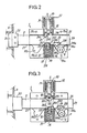
- the high position of the core 30 is defined by the position of the lug 35 on the upper longitudinal edge 25 of the bolt, as shown in FIG. 2. This high position corresponds in practice to a position of maximum penetration of the core into the coil by bonding the core 30 against the fixed armature of the powered electromagnet 3, and to an attractive force exerted upwards. on the core equal to or very substantially greater than the weight of the core 30 and of the plug 33.
- the low position of the core 30 is defined by the position of the lug 35 in the bottom of the v-notch 24 of the bolt, as shown in fig. 4.
- a descent of a few tenths of a millimeter, from the core with respect to its high position corresponds to an already weaker attractive force than the weight of the core 30 and of the bushel 33.
- the head 20 of the bolt 2 has come out of the mortise of the headrest of the lock bolt under the action of the return spring 50.
- the bolt is retained forwards by the pin 371 of the piston 37 abutting against the rear side 261 of the small notch 26.
- the flange 511 of the front guide 51 of the spring 50 is not necessarily in abutment against the rear edge 11a of the body 1.
- the central transverse lug 35 rests on the upper longitudinal edge 25 of the bolt behind the vee notch 24.
- the core 30 is at full travel in the high position in the coil 31, as shown in FIG. 2.
- the arm 40 of the follower is applied against the front side 140a of the vee notch 14a by the spring 42.
- the end of the arm 40 is substantially behind the front side 280 of the large notch 28.
- the authorization to open the door is controlled by removing the power from the coil 31 of the electromagnet 3.
- the start of the reversal of the latch bolt 2 is carried out as previously by rotation of the arm 40 of follower 4 to the rear.
- the stud 371 of the piston 37 is released from the rectangular lower notch 26 of the bolt, as shown in FIG. 4. This allows the recoil of the bolt to be continued by rotation of the arm 40 of the follower 4 always following the arrow F, until the arm 40 abuts against the rear side 141 a of the notch 14a.
- the bolt 2 is then in the open position for which the head 20 of the bolt is completely released from the keeper G, as shown in FIG. 5.
- the core 30 and the plug 33 rises following the sliding of the lug 35 on the front side 240 of the vee notch 24, then on the upper edge 25 of the bolt 2.
- the lower edge 27 of the bolt slides against the stud 371 of the piston 37 and the spring 36 is compressed in the chamber 334 by the raising of the plug 33.
- the upper rod 6s descends and the lower rod 6i rises thanks to the recoil of the lug 61 sliding horizontally in the crossed slots 60s and 60i and in the longitudinal slot 16b. Under these conditions, the three-point lock is in the open position.
- the plug 33 and the core 30 are in the high position.
- the advance of the bolt 2 drives via the lug 61 the rise of the upper rod 6s and the descent of the lower rod 6i.
- the displacement of the rods is accentuated by the pulling of the spring 62 although this is not essential.
- the coil 31 of the electromagnet 3 is energized before the handle of the lock is released, everything goes as above except that the core 30 is held in the high position in the coil 31 and the notch in vé 24 of the bolt passes below the lug 35 without receiving it.
- the coil 31 is supplied when the handle is released after opening the door, the bolt 2 is returned to the position shown in FIG. 2. In this case, the door cannot be closed since the core 30 and plug 33 are kept in the high position and consequently the stud 371 of the piston 37 cannot be released from the notch 26 for the retraction of the bolt.
- the second embodiment shown in figs. 6 to 9 overcomes this drawback and in particular allows the lock to be locked in the closed position without the coil being necessarily supplied.
- the lock according to the second embodiment comprises the elements of the first embodiment with the necessary addition of the return spring 42 of the follower 4 as well as a miniature switch or contactor 8 and a lever 43 controlling the contactor 8.
- the housing of the contactor 8 is fixed to the plate 7a traversed by the follower 4.
- the contactor 8 is connected in series between one of the terminals 32 of the coil 31, and one of the terminals of the power source of the coil.
- the movable contact 80 of the contactor 8 is integral with a small slide 81 sliding parallel to the axis X'X, completely passing through the housing of the contactor.
- a small spring 82 contained in the housing of the contactor 8 recalls rearward the movable contact 80 in the closed position for which the rear end of the slide 81 projects on the rear side of the housing.
- the lever 43 is fixed by two screws to the periphery of the inner pin of the follower 4, above the plate 7a.
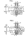
- the lever 43 When the arm 40 of the follower is applied against the front side 140a of the notch 14a by the traction of the spring 42, the lever 43 is substantially vertical and is pressed against the rear side of the housing of the contactor 8, which pushes towards the before the movable contact 80 and opens the contactor 8, as shown in fig. 6.
- the contactor 8 is closed when the follower has turned a small angle so as to release the end of the lever behind the slide 81, which allows the spring 82 to apply the movable contact 80 to the stationary contact 83 of the contactor as shown in figs. 8 and 9.
- the authorized opening of the door is carried out in a manner analogous to FIGS. 4 and 5 by disconnecting the power source.
- the door can be closed, whether the remote power supply to the coil is cut or not.
- a closure can be effected by abruptly pushing the door leaf.
- the head 20 of the latch bolt comes into contact with the keeper G of the lock, which pushes the bolt 2 backwards.
- the front side 260 of the small lower notch 26 abuts against the stud 371 of the piston 37, the front side 280 of the large lower notch 28 has already pushed the arm 40 of the follower in sufficient rotation to release the lever 43 on the rear side of the housing of the contactor 8, as shown in FIG. 7.
- the closing of the door by penetration of the head 20 into the keeper G is carried out as according to the first embodiment thanks to the thrust of the bolt 2 exerted forwards by the spring 50 and thanks to the thrust of the piston 37 in the notch 26 exerted upwards by the spring 36.
- the arm 40 of the follower 4 is applied against the front side 280 of the notch 28 by the traction exerted by the strand 420 of the spring 42 when the bolt advances.
- the lever 43 pushes the small slide 81, which releases the movable contact 80 from the stationary contact 83 and opens the contactor 8.
- the power source of the coil 31 present or not is in any case without effect thanks to the opening of the contactor 8 for the closed position of the door.
Landscapes
- Physics & Mathematics (AREA)
- Electromagnetism (AREA)
- Lock And Its Accessories (AREA)
Claims (10)
Applications Claiming Priority (2)
| Application Number | Priority Date | Filing Date | Title |
|---|---|---|---|
| FR8400385 | 1984-01-12 | ||
| FR8400385A FR2558202B1 (fr) | 1984-01-12 | 1984-01-12 | Serrure electromecanique |
Publications (3)
| Publication Number | Publication Date |
|---|---|
| EP0148701A2 EP0148701A2 (de) | 1985-07-17 |
| EP0148701A3 EP0148701A3 (en) | 1985-08-21 |
| EP0148701B1 true EP0148701B1 (de) | 1988-06-01 |
Family
ID=9300027
Family Applications (1)
| Application Number | Title | Priority Date | Filing Date |
|---|---|---|---|
| EP19840402728 Expired EP0148701B1 (de) | 1984-01-12 | 1984-12-27 | Elektromechanisches Schloss |
Country Status (3)
| Country | Link |
|---|---|
| EP (1) | EP0148701B1 (de) |
| DE (1) | DE3471711D1 (de) |
| FR (1) | FR2558202B1 (de) |
Families Citing this family (15)
| Publication number | Priority date | Publication date | Assignee | Title |
|---|---|---|---|---|
| GB8622120D0 (en) * | 1986-09-13 | 1986-10-22 | Chubb & Sons Lock & Safe Co | Locking mechanisms |
| GB8827906D0 (en) * | 1988-11-30 | 1989-01-05 | Yale Security Prod Ltd | Electromagnetically activated mechanisms |
| GB2231367B (en) * | 1989-04-13 | 1993-05-19 | Chubb Lips Nederland Bv | Lock with an electromechanical release mechanism |
| DE3926132A1 (de) * | 1989-08-08 | 1991-02-14 | Sitec Gmbh Sicherheitseinricht | Schliessfach mit beidseitig angeordneten tueren |
| DE4036579A1 (de) * | 1990-11-16 | 1992-05-21 | Burg Waechter Kg Luelin A | Elektronisches schloss |
| RU2124104C1 (ru) * | 1994-09-01 | 1998-12-27 | Демидов Леонид Анатольевич | Электромагнитный замок |
| FR2726026B1 (fr) * | 1994-10-20 | 1996-11-29 | Deny | Serrure electromecanique pour issue de secours a double action |
| DE19628994A1 (de) * | 1996-07-18 | 1998-01-22 | Mauer Gmbh | Elektromagnetisch betätigbares Schloß |
| US6082153A (en) * | 1997-09-17 | 2000-07-04 | Medeco Security Locks, Inc. | Anti-tampering device for use with spring-loaded electronically moved pin locking mechanisms in electronic locks and the like |
| WO2000011291A1 (en) * | 1998-08-20 | 2000-03-02 | Sergei Nikolaevich Gavrilov | Electromechanical code lock and method for closing the same |
| US6564600B1 (en) * | 1999-03-08 | 2003-05-20 | Videx, Inc. | Electronic access control device |
| KR100391938B1 (ko) * | 1999-07-07 | 2003-08-25 | 주식회사 보고테크 | 도어 잠금장치 |
| US8495899B2 (en) * | 2011-05-23 | 2013-07-30 | Klaus W. Gartner | Electromechanical lock |
| KR102512205B1 (ko) * | 2016-02-18 | 2023-03-22 | 삼성전자주식회사 | 도어 락킹장치 및 이를 갖는 세탁기 |
| CN116968480A (zh) * | 2023-08-14 | 2023-10-31 | 营口市成利汽保设备加工有限公司 | 一种轮胎拆装机用轴式气动锁紧装置 |
Family Cites Families (1)
| Publication number | Priority date | Publication date | Assignee | Title |
|---|---|---|---|---|
| GB191513910A (en) * | 1915-09-30 | 1916-08-31 | Edward Harold Stone | Improvements relating to Automatic Locks for Railway Carraige Doors. |
-
1984
- 1984-01-12 FR FR8400385A patent/FR2558202B1/fr not_active Expired
- 1984-12-27 DE DE8484402728T patent/DE3471711D1/de not_active Expired
- 1984-12-27 EP EP19840402728 patent/EP0148701B1/de not_active Expired
Also Published As
| Publication number | Publication date |
|---|---|
| FR2558202A1 (fr) | 1985-07-19 |
| EP0148701A3 (en) | 1985-08-21 |
| EP0148701A2 (de) | 1985-07-17 |
| FR2558202B1 (fr) | 1986-04-11 |
| DE3471711D1 (en) | 1988-07-07 |
Similar Documents
| Publication | Publication Date | Title |
|---|---|---|
| EP0148701A2 (de) | Elektromechanisches Schloss | |
| EP0235041B1 (de) | Verriegelungsvorrichtung, zum Beispiel für einen Riegelverschluss | |
| EP0082761B1 (de) | Kraftfahrzeugtürschloss | |
| FR2617893A1 (fr) | Dispositif de verrouillage et de deverrouillage d'un moyen d'issue de secours | |
| EP1901327B1 (de) | Mechanismus mit zwei stabilen Positionen und diesen umfassende elektrische Steuervorrichtung | |
| EP0159238A1 (de) | Elektromechanishe Schlossbedienung und Kraftfahrzeugtürschloss damit versehen | |
| EP0292361B1 (de) | Elektrisch betätigbares Schloss | |
| CA1203825A (fr) | Dispositif amovible de verrouillage d'un contacteur dans sa position de travail | |
| CH635911A5 (fr) | Valve pour fluide a commande manuelle. | |
| FR2521201A1 (fr) | Cle a poussoir mobile et barillet de surete utilisant ladite cle | |
| FR2558567A1 (fr) | Dispositif de double commande mecanique d'un interrupteur, et machine en comportant application | |
| EP0928869B1 (de) | Verriegelungsbeschlag für Tür, Fenstertür oder dergleichen | |
| FR2808552A1 (fr) | Serrure a deverrouillage mecanique et electrique | |
| EP1278225B1 (de) | Schnelleinschaltvorrichtung | |
| WO2005078757A2 (fr) | Dispositif de manoeuvre bistable d’un arbre mobile non traversant et coupe-circuit de batterie comprenant un tel dispositif | |
| EP1317784B1 (de) | Elektrische schalteinheit | |
| EP0032870B1 (de) | Auf ein Gestell montierbares Gerät zum Steuern der Bewegung eines Armes und Anwendung dieses Gerätes als Schalter | |
| FR2656026A1 (fr) | Dispositif de commande electrique d'un levier pivotant maintenu libre aux deux extremites de sa course et serrure comportant ce dispositif. | |
| FR2713822A1 (fr) | Rupteur de circuit électrique. | |
| EP0389728B1 (de) | Elektromotorisch angetriebenes Sicherheitsschloss mit doppeltem Riegel | |
| EP1458945B1 (de) | Elektrische verriegelung | |
| EP2586938B1 (de) | Verriegelungsvorrichtung für ein Öffnungselement | |
| EP0410886A1 (de) | Drehgriff mit Entriegelungsdruckknopf | |
| FR2552809A1 (fr) | Serrure a pene demi-tour | |
| EP0246131B1 (de) | Elektrische, bistabile Schaltvorrichtung |
Legal Events
| Date | Code | Title | Description |
|---|---|---|---|
| PUAI | Public reference made under article 153(3) epc to a published international application that has entered the european phase |
Free format text: ORIGINAL CODE: 0009012 |
|
| PUAL | Search report despatched |
Free format text: ORIGINAL CODE: 0009013 |
|
| AK | Designated contracting states |
Designated state(s): CH DE GB IT LI |
|
| AK | Designated contracting states |
Designated state(s): CH DE GB IT LI |
|
| 17P | Request for examination filed |
Effective date: 19851219 |
|
| 17Q | First examination report despatched |
Effective date: 19870305 |
|
| ITF | It: translation for a ep patent filed | ||
| GRAA | (expected) grant |
Free format text: ORIGINAL CODE: 0009210 |
|
| AK | Designated contracting states |
Kind code of ref document: B1 Designated state(s): CH DE GB IT LI |
|
| GBT | Gb: translation of ep patent filed (gb section 77(6)(a)/1977) | ||
| REF | Corresponds to: |
Ref document number: 3471711 Country of ref document: DE Date of ref document: 19880707 |
|
| PLBE | No opposition filed within time limit |
Free format text: ORIGINAL CODE: 0009261 |
|
| STAA | Information on the status of an ep patent application or granted ep patent |
Free format text: STATUS: NO OPPOSITION FILED WITHIN TIME LIMIT |
|
| 26N | No opposition filed | ||
| PGFP | Annual fee paid to national office [announced via postgrant information from national office to epo] |
Ref country code: GB Payment date: 19911129 Year of fee payment: 8 |
|
| ITTA | It: last paid annual fee | ||
| PGFP | Annual fee paid to national office [announced via postgrant information from national office to epo] |
Ref country code: DE Payment date: 19911231 Year of fee payment: 8 |
|
| PGFP | Annual fee paid to national office [announced via postgrant information from national office to epo] |
Ref country code: CH Payment date: 19920107 Year of fee payment: 8 |
|
| PG25 | Lapsed in a contracting state [announced via postgrant information from national office to epo] |
Ref country code: GB Effective date: 19921227 |
|
| PG25 | Lapsed in a contracting state [announced via postgrant information from national office to epo] |
Ref country code: LI Effective date: 19921231 Ref country code: CH Effective date: 19921231 |
|
| GBPC | Gb: european patent ceased through non-payment of renewal fee |
Effective date: 19921227 |
|
| REG | Reference to a national code |
Ref country code: CH Ref legal event code: PL |
|
| PG25 | Lapsed in a contracting state [announced via postgrant information from national office to epo] |
Ref country code: DE Effective date: 19930901 |