EP0148043B1 - Dispositif pour le bombage de plaques de verre - Google Patents
Dispositif pour le bombage de plaques de verre Download PDFInfo
- Publication number
- EP0148043B1 EP0148043B1 EP84402260A EP84402260A EP0148043B1 EP 0148043 B1 EP0148043 B1 EP 0148043B1 EP 84402260 A EP84402260 A EP 84402260A EP 84402260 A EP84402260 A EP 84402260A EP 0148043 B1 EP0148043 B1 EP 0148043B1
- Authority
- EP
- European Patent Office
- Prior art keywords
- glass plates
- shaping
- bed
- chassis
- pivoting
- Prior art date
- Legal status (The legal status is an assumption and is not a legal conclusion. Google has not performed a legal analysis and makes no representation as to the accuracy of the status listed.)
- Expired
Links
- 239000011521 glass Substances 0.000 title claims description 51
- 238000005452 bending Methods 0.000 title description 37
- 238000007493 shaping process Methods 0.000 claims description 66
- 238000011144 upstream manufacturing Methods 0.000 claims description 20
- 230000000694 effects Effects 0.000 claims description 4
- XLYOFNOQVPJJNP-UHFFFAOYSA-N water Substances O XLYOFNOQVPJJNP-UHFFFAOYSA-N 0.000 claims description 2
- 238000004064 recycling Methods 0.000 claims 1
- 238000003303 reheating Methods 0.000 description 9
- 238000009434 installation Methods 0.000 description 8
- 238000010791 quenching Methods 0.000 description 6
- 230000000171 quenching effect Effects 0.000 description 6
- 238000010438 heat treatment Methods 0.000 description 4
- 238000001816 cooling Methods 0.000 description 3
- 238000004519 manufacturing process Methods 0.000 description 3
- 239000005357 flat glass Substances 0.000 description 2
- 230000003287 optical effect Effects 0.000 description 2
- 230000000750 progressive effect Effects 0.000 description 2
- 230000000717 retained effect Effects 0.000 description 2
- 238000005496 tempering Methods 0.000 description 2
- 241001639412 Verres Species 0.000 description 1
- 230000006978 adaptation Effects 0.000 description 1
- 230000002411 adverse Effects 0.000 description 1
- 238000007664 blowing Methods 0.000 description 1
- 238000010276 construction Methods 0.000 description 1
- 238000010586 diagram Methods 0.000 description 1
- 210000000629 knee joint Anatomy 0.000 description 1
- 230000003068 static effect Effects 0.000 description 1
- 239000013589 supplement Substances 0.000 description 1
Images


Classifications
-
- C—CHEMISTRY; METALLURGY
- C03—GLASS; MINERAL OR SLAG WOOL
- C03B—MANUFACTURE, SHAPING, OR SUPPLEMENTARY PROCESSES
- C03B23/00—Re-forming shaped glass
- C03B23/02—Re-forming glass sheets
- C03B23/023—Re-forming glass sheets by bending
- C03B23/025—Re-forming glass sheets by bending by gravity
- C03B23/027—Re-forming glass sheets by bending by gravity with moulds having at least two upward pivotable mould sections
-
- C—CHEMISTRY; METALLURGY
- C03—GLASS; MINERAL OR SLAG WOOL
- C03B—MANUFACTURE, SHAPING, OR SUPPLEMENTARY PROCESSES
- C03B23/00—Re-forming shaped glass
- C03B23/02—Re-forming glass sheets
- C03B23/023—Re-forming glass sheets by bending
- C03B23/025—Re-forming glass sheets by bending by gravity
- C03B23/0252—Re-forming glass sheets by bending by gravity by gravity only, e.g. sagging
- C03B23/0254—Re-forming glass sheets by bending by gravity by gravity only, e.g. sagging in a continuous way, e.g. gravity roll bending
-
- C—CHEMISTRY; METALLURGY
- C03—GLASS; MINERAL OR SLAG WOOL
- C03B—MANUFACTURE, SHAPING, OR SUPPLEMENTARY PROCESSES
- C03B35/00—Transporting of glass products during their manufacture, e.g. hot glass lenses, prisms
- C03B35/14—Transporting hot glass sheets or ribbons, e.g. by heat-resistant conveyor belts or bands
- C03B35/16—Transporting hot glass sheets or ribbons, e.g. by heat-resistant conveyor belts or bands by roller conveyors
- C03B35/161—Transporting hot glass sheets or ribbons, e.g. by heat-resistant conveyor belts or bands by roller conveyors specially adapted for bent sheets or ribbons
-
- C—CHEMISTRY; METALLURGY
- C03—GLASS; MINERAL OR SLAG WOOL
- C03B—MANUFACTURE, SHAPING, OR SUPPLEMENTARY PROCESSES
- C03B35/00—Transporting of glass products during their manufacture, e.g. hot glass lenses, prisms
- C03B35/14—Transporting hot glass sheets or ribbons, e.g. by heat-resistant conveyor belts or bands
- C03B35/16—Transporting hot glass sheets or ribbons, e.g. by heat-resistant conveyor belts or bands by roller conveyors
- C03B35/163—Drive means, clutches, gearing or drive speed control means
-
- C—CHEMISTRY; METALLURGY
- C03—GLASS; MINERAL OR SLAG WOOL
- C03B—MANUFACTURE, SHAPING, OR SUPPLEMENTARY PROCESSES
- C03B35/00—Transporting of glass products during their manufacture, e.g. hot glass lenses, prisms
- C03B35/14—Transporting hot glass sheets or ribbons, e.g. by heat-resistant conveyor belts or bands
- C03B35/16—Transporting hot glass sheets or ribbons, e.g. by heat-resistant conveyor belts or bands by roller conveyors
- C03B35/18—Construction of the conveyor rollers ; Materials, coatings or coverings thereof
- C03B35/185—Construction of the conveyor rollers ; Materials, coatings or coverings thereof having a discontinuous surface for contacting the sheets or ribbons other than cloth or fabric, e.g. having protrusions or depressions, spirally wound cable, projecting discs or tires
Definitions
- the present invention relates to the bending, under the effect of their own weight, of glass plates moving in a horizontal or substantially horizontal position, using a device comprising a shaping bed made of rotating shaping elements which have in an upstream part, in contact with the glass plates, or as they move forward, generators whose casing becomes more and more curved, these shaping elements of this upstream part being mounted on a frame adjustable in height and tiltable in the longitudinal direction of movement of the plates, by pivoting about a transverse horizontal axis located at its upstream end.
- the rotating shaping elements of these devices can be of various configurations.
- rollers with a curved profile, mounted for rotation, as shown in patent document US-A-4 139 359.
- They may also be rods or cylindrical rotating rollers which are flexible and elastic enough to be deformed by inclination of their ends relative to the horizontal and so that this change in shape is compatible and is preserved with rotation.
- deformable rollers are described, for example, in patent document US-A-4,226,608.
- the rotating shaping elements also participate in transport and are formed of flexible tubular sheaths rotated on themselves and around rigid curved rods.
- the adjustment of the radius of curvature of the bending shape, as well as the progression of its curvature in the direction of transport of the glass plates is achieved by the fact that the various curved rods are mounted so that they can be tilted by pivoting around 'an axis which passes through their ends and can be adjusted to different inclinations from each other, which separates them more and more from the transport plane in which the glass plates are located when they arrive.
- an upstream part that is to say the curved rods surrounded by their rotating tubular sheaths located in a head part of the device, are mounted on a frame articulated at its upstream end on a fixed transverse pivot axis located at the level of the cylindrical transport rollers of the previous installation which brings the glass plates to the device.
- each curved rod of this upstream part can be more or less inclined to vary the radius of curvature that each shaping element which contains it presents under the glass plates
- the frame which supports all the shaping elements can pivot around the transverse axis situated at its upstream end so that the vertices of the curvatures of the shaping elements always remain at the level at which the still flat glass plates are introduced into the bending device.
- This upstream part of the bending device often follows a downstream part in which all the curved rods have the same maximum inclination identical to that of the last rod at the end of the upstream part.
- the bending is to be carried out in such a way that the longitudinal edges of the glass volumes extending parallel to the direction of transport remain at the same level, this is not possible, with the device known, that for a determined width of the glass plates.
- the position of their longitudinal edges on the shaping elements is necessarily different and the level of these edges is necessarily lower or higher, which affects the optical quality of the curved glass plates and can influence it adversely.
- the object of the invention is to develop bending devices of the specified type, which make it possible to satisfy the most varied requirements relative to the level of specific zones of the treated glass plates.
- the bending device must be as flexible as it offers the possibility, as well in the case of convex shaping beds as in the case of concave beds, regardless of the size of the glass sheets to be bent, to maintain either the central line at the top of the curvature, or the longitudinal edges of the glass plates, at the initial transport level of the flat glass plates, during bending and possibly the subsequent tempering and / or cooling.
- the settings of the bending device according to the invention can be modified so that, in particular in the case of a bed of concave conformation, the longitudinal edges of the glass plates, parallel to the direction of transport, remain constantly exactly at the same level, both in the reheating oven which precedes the bending device, in the bending device itself, and in the following quenching and / or cooling installations.
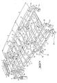
- FIG. 1 illustrates the basic structure of a bending device according to the invention.
- Baking glass plates 1 are heated to the bending temperature in a reheating furnace not shown here, in which they are transported in the direction of the arrow F by means of transport rollers 2 driven in rotation.
- the reheating furnace is followed by the bending station.
- This bending station comprises a shaping bed enclosed in a heated enclosure, not shown, and consisting of a plurality of shaping elements 3 rotating on which the glass plates 1 rest. Under the effect of their own weight, the glass plates 1 conform to the shape of the shaping bed.
- Each rotating conformation element 3 comprises a flexible tubular sheath 4, resistant to torsion, driven in rotation on itself around a rigid curved rod 5.
- All the curved rods have the same shape and the same radius of curvature, each is curved in its median part while its ends 6 are straightened with respect to this median part so that they are arranged in the extension one of the other and form a pivot axis SS 'around which the curved rod can tint.
- These ends 6 of the curved rods are pivotally mounted in longitudinal members 8 parallel to the direction of transport of the glass plates 1, these longitudinal members constituting a support frame for the shaping bed.
- each curved rod 5 is provided with a crank 9 which serves to tilt it into the desired angular position.
- a roller 10 is mounted on the end of each crank 9 and all the rollers 10 associated with all the curved rods 5 of the shaping bed are guided in a U-shaped rail referenced 11 in a first part A of the conformation, referenced 12 in a second part B which follows on from the first.
- the curved rods 5 are all inclined differently, the inclination progressively increasing from one rod to the other, thus constituting a shaping bed whose curvature in the transverse direction perpendicular to the direction of advancement of the glass plates 1, is increasing.
- the shaping bed is concave.
- the rail 11 is pivotally mounted around a transverse articulation 14 located at its upstream end, which makes it possible to tilt it in the direction of progression of the plates of glass, relative to the frame determined by the side members 8, in particular relative to the horizontal if this frame is arranged horizontally.
- a lever 16 belonging to a toggle joint mechanism 17, 18, 19 described in detail below, serves to ensure the pivoting of the rail 11 around the joint 14.
- the rail 12 in which the rollers 10 at the end of the cranks 9 of bent rods 5 roll in the part B of the installation is articulated on an axis 20 belonging to the downstream end of the rail 11. It is movable in height while by remaining parallel to itself, in particular by remaining horizontal, by action on the lever 16 which controls the deformation of two contiguous parallelograms, the first formed by a connecting rod 18, two connecting rods 17 each attached to two points distant from the rail 12, this portion rail 12 constituting the fourth side of the parallelogram, the second formed by the rod 18 common to the two parallelograms, two arms 19 one of which is extended by the lever 16, the fourth side being constituted by a portion of frame not referenced located between two fixed points 21 for attachment of the two arms 19.
- the variation in height of the rail 12 causes makes the connection between said rail 12 and rail 11, the inclination of rail 11 by pivoting around the articulation 14.
- the bent rods 5 "'of part B of the shaping bed are pivotally mounted in a frame 22 which is articulated around the joints 23 on the downstream end of the side members 8 of the frame of part A of the shaping bed.
- 22 is mounted on a knee joint mechanism 24, 25, 26, of the same type as that which carries the rail 12.
- This mechanism 24, 25, 26, can be actuated by a lever 27, which moves the chassis 22 parallel to itself, in the direction of the height and what also changes the inclination of the chassis formed of the side members 8 of the first part A of the shaping bed by pivoting it around the joints 28, located on a transverse horizontal axis XX 'at the head of the installation.
- the lever 16 and the toggle mechanism 17, 18, 19 makes it possible not only to adjust the radius of curvature of the shaping bed, but also to orient the curvature, that is to say to make the bed concave or convex.
- the lever 27, meanwhile, is used to adjust the height of the portion B of the shaping bed, and consequently the inclination of the portion A of the said bed, so that for determined widths of the glass plates 1, namely the line disposed longitudinally in the center of said plates 1, ie the longitudinal edges remain at a constant level.
- the bearings 28 of the side members 8 which constitute the supporting frame of the curved rods 5 in the portion A of the shaping bed are adjustable in height. To do this, they are supported by rods 33 of lifting cylinders 34, rods 33 movable by action on the drive shaft 35.
- the articulation 14 of the U-shaped rail 11 is mounted on a rod 37 of a lifting cylinder 38, which rod can move up or down by action on the drive shaft 39.
- the flexible tubular sheaths 4 resistant to torsion, which cover the curved rods 5 are rotated on themselves around these rods by means of toothed pinions 31 of which they are integral and which mesh on one or more chains 30.
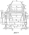
- FIG. 2 shows in longitudinal section along the median axis the assembly of a plant for manufacturing curved glass plates, comprising a bending device according to the invention.
- This bending device is preceded by a reheating oven 58 fitted with rollers 2 for transporting the glass plates in the direction of the arrow F, and followed by a quenching station 59.
- Elements of the bending station are shown in FIG. 1 , namely mainly the shaping elements 3 formed of curved rods 5 surrounded by their flexible tubular sheaths 4 driven in rotation.
- shaping elements 3 determine a shaping bed in two parts: a first part A in which the curvature presented to the glass plates 1 is at entry practically zero, to increase until becoming maximum at the level of the last element of this part A consisting of its curved rod 5 "and its sheath, and a second part B in which the curvature is constant and equal to the curvature established by the last shaping element of part A.
- the curved rods 5 are pivotally mounted in longitudinal members 42 arranged longitudinally and in the second part B, they are mounted in longitudinal members 43.
- the longitudinal members 43 are articulated on the downstream end of the longitudinal members 42 by an articulation 44, the longitudinal members 43 of part B of the shaping bed rest on articulations 45 and 46 mounted on the rods 47 and 48 of lifting cylinders 49 and 50 actuated by the shafts 51 and 52.
- the longitudinal members 42 of part A of the shaping bed are supported on the one hand by the articulation 44, and on the other hand at their upstream end on an articulation 53 situated on a transverse horizontal axis YY 'and mounted on the rod 54 of a lifting jack 55 actuated by the shaft 56.
- the jacks 49, 50 and 55 rest, at the same time as the other parts of the installation, in particular the reheating oven 58 and the quenching station 59 on a general frame 57.
- the tempering station 59 essentially comprises means for supporting curved glass plates, namely curved rods 5 surrounded by their flexible tubular sheaths, having the same orientation as the rods 5 of part B of the shaping bed, and boxes supply air 60 and 61 delivering their cooling air through tubular nozzles 62.
- FIGS. 3 and 4 Another interesting embodiment of a bending device according to the invention is illustrated in FIGS. 3 and 4.
- the beams which support the curved rods of the second part B of the shaping bed are referenced 63 and they form a frame which rests on pillars 64.
- the beams which support the curved rods of the first part A of the shaping bed are referenced 65 and are mounted on joints 66, 67.
- the joints 67 are located on a transverse horizontal axis ZZ '.
- Each front or upstream joint 67 is carried by a rod 69 of a lifting cylinder 70 actuated by a shaft 71, while each rear or downstream joint 66 is carried by a pillar 68.
- the set of pillars 64, 68 and of the jack 70 rests on a frame 75 itself carried by jacks 73 and 74.
- the height adjustment of the shaping bed as a whole setting in which account is taken of the radius of curvature to be given to the glass plates, of the width of said plates in order to orient, notably horizontally, said shaping bed, is first performs using the lifting cylinders 73 and 74. They bring the frame 75 on which the pillars 64, 68 and the cylinder 70 carrying the shaping bed rest, to the desired height.
- cranks fitted on the curved rods, the rollers, the support rails necessary for the orientation of the curved rods still exist in this embodiment, but they are not shown so as not to clutter the drawing.
- enclosures 78 in the form of a funnel, closed at their upper part by perforated plates 80, supplied with gas under pressure, generally air, heated to around 650 ° C, via supply lines 79.
- gas under pressure generally air
- the hot air emitted vertically from bottom to top, through the perforations in the plates 80, is directed towards the underside of the glass plates and thus forms a homogeneous flow and gas uniform providing support to said glass plates.
- the overpressure in the enclosures 78 is approximately 10 to 60 mm of water column (10 to 60 mm CE) or 100 to 600 Pa, that the perforations through the plates 80 have a diameter of 12 to 15 mm and are evenly distributed in both transverse and longitudinal directions with the same pitch of 25 to 35 mm, that the distance between the perforated plates 80 and the glass plates is such that at the level of the glass the static pressure is negligible compared to the dynamic pressure , which corresponds to distances between the plates 80 and the glass plates of the order of 100 to 300 mm, a uniform and uniform pressure is obtained on the glass plates of the order of 2 to 30 mm CE which allows to take charge of around 20 to 80% of the weight of the glass plates, thus reducing the pressure exerted by the shaping elements on said plates and significantly improving the optical quality.
- hood 82 for hot gas suction.
- This hood 82 communicates with an exhaust duct 83 then with a non-illustrated sheath, which recycles the recovered gas.
- This gas receives a heating supplement and is reinjected into the enclosures 78 by the supply lines 79.
- heating elements 86 attached to a support 87 retained by hooking tabs 88.
- the quenching station 59 Downstream of the bending station, the quenching station 59 is arranged with blowing boxes 60 and 61 delivering the quenching gas by tubular nozzles 62.
- FIG. 4 are visible other details concerning the construction and the mounting of the bending station shown in FIG. 3.
- the crank 9 provided at the end of the curved rod 5 ′, first of the curved rods 5, provided with the roller 10 which is guided in the U-shaped rail 11.
- the curved middle part of this rod 5 ′, its ends and the crank 9 are in the same horizontal plane.
- the U-shaped rail II is pivotally mounted on the articulation 14 fixed on the rod 37 of the jack 38.
- the tubular sheath 4 is integral with a pinion 31 which meshes with a chain 30, this pinion 31 being disposed outside the enclosure 84 which encloses the bending station.
- the jack 38 rests, like the jack 70 placed under the upstream end of the part A of the shaping bed, on the frame 75 which for its part can be adjusted in height by the lifting jacks 73.
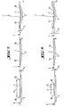
- FIGS 5 and 6 illustrate the effect of the measures which make it possible to implement the device of the invention.
- Figure 5 shows a glass plate 1 of width b, to be curved with a radius of curvature R.
- Figure 6 shows a glass plate 1 'of width b 2 less than b i which must also be curved with a radius of curvature R.
- the transport plane E is determined by the upper generatrices of the cylindrical transport rollers 2.
- the bearings of said rod 5 ′ are raised by a height h, so that the longitudinal edges 92 of the glass plate 1 which are located in the curved portion of the curved rod 5 ', slightly lowered with respect to its ends due to the inclination and the curvature of said rod, remain at the level of the transport plane E.
- the central zone of the glass plate which marries the part curved middle of the rod 5 ' collapses below the level of the edges 9 2.
- the bearings of the following curved rods 5 are raised more and more, to keep the edges 92 always at the same level while the center sinks more and more.
- the rod 5 "last of the rods 5 of the portion A of the bed conformation has its bearings shifted upwards by a height h 2 above the transport plane E, notably greater than h 1 .
- the transverse axis of pivoting of the chassis supporting the shaping bed can be adjusted in height, and said chassis can be tilted by pivoting around this transverse axis making it possible to gradually increase or decrease, depending on the direction of the curvature of the shaping bed, the height of the bearings of the curved rods.
Applications Claiming Priority (2)
| Application Number | Priority Date | Filing Date | Title |
|---|---|---|---|
| FR8317830 | 1983-11-09 | ||
| FR8317830A FR2554437B1 (fr) | 1983-11-09 | 1983-11-09 | Dispositif de bombage de plaques de verre |
Publications (2)
| Publication Number | Publication Date |
|---|---|
| EP0148043A1 EP0148043A1 (fr) | 1985-07-10 |
| EP0148043B1 true EP0148043B1 (fr) | 1988-05-18 |
Family
ID=9293944
Family Applications (1)
| Application Number | Title | Priority Date | Filing Date |
|---|---|---|---|
| EP84402260A Expired EP0148043B1 (fr) | 1983-11-09 | 1984-11-09 | Dispositif pour le bombage de plaques de verre |
Country Status (12)
| Country | Link |
|---|---|
| US (1) | US4575389A (xx) |
| EP (1) | EP0148043B1 (xx) |
| JP (1) | JPS60171238A (xx) |
| KR (1) | KR850003879A (xx) |
| BR (1) | BR8405698A (xx) |
| CA (1) | CA1244243A (xx) |
| DE (1) | DE3471294D1 (xx) |
| ES (1) | ES537493A0 (xx) |
| FI (1) | FI75332C (xx) |
| FR (1) | FR2554437B1 (xx) |
| PT (1) | PT79476B (xx) |
| YU (1) | YU43938B (xx) |
Families Citing this family (12)
| Publication number | Priority date | Publication date | Assignee | Title |
|---|---|---|---|---|
| US4670036A (en) * | 1986-06-04 | 1987-06-02 | Libbey-Owens-Ford Co. | Conveying, supporting and shaping glass sheets |
| FR2604992B1 (fr) * | 1986-10-01 | 1988-12-02 | Saint Gobain Vitrage | Bombage et trempe de plaques de verre defilant sur un lit de conformation courbe dans la direction de defilement |
| US4787504A (en) * | 1986-10-06 | 1988-11-29 | Ppg Industries, Inc. | Adjustable radius conveyor roll |
| US5176733A (en) * | 1988-12-27 | 1993-01-05 | Ford Motor Company | Method and apparatus for directed energy glass heating |
| DE59309533D1 (de) * | 1993-07-15 | 1999-05-27 | Cristales Automatrices De Jali | Verfahren und Vorrichtung zum dreidimensionalen Verformen von Platten, insbesondere Glasscheiben |
| US5395415A (en) * | 1993-12-13 | 1995-03-07 | Libbey-Owens-Ford Co. | Method and apparatus for conveying and shaping glass sheets |
| FI97539C (fi) * | 1995-08-25 | 1997-01-10 | Tambest Oy | Taivutusmuotti lasilevyjen taivuttamiseksi |
| DE19744875C2 (de) * | 1997-10-10 | 2000-03-30 | Kramer Carl | Vorrichtung zum Biegen von Flachglas |
| WO1999065833A1 (fr) * | 1998-06-19 | 1999-12-23 | Asahi Glass Company Ltd. | Procede et dispositif de cintrage d'un panneau de verre |
| FI106952B (fi) * | 1999-11-01 | 2001-05-15 | Uniglass Engineering Oy | Menetelmä lasin taivuttamiseksi ja lasintaivutusmuotti |
| FI109420B (fi) * | 1999-11-01 | 2002-07-31 | Uniglass Engineering Oy | Menetelmä ja laitteisto lasin taivuttamiseksi |
| FI115768B (fi) * | 2003-02-21 | 2005-07-15 | Tamglass Ltd Oy | Menetelmä ja laite kahteen suuntaan kaarevan lasilevyn taivuttamiseksi ja karkaisemiseksi tai lämpölujittamiseksi |
Family Cites Families (4)
| Publication number | Priority date | Publication date | Assignee | Title |
|---|---|---|---|---|
| US3223498A (en) * | 1962-02-27 | 1965-12-14 | Pittsburgh Plate Glass Co | Heat treatment of conveyed glass and apparatus therefor |
| FR2312463A1 (fr) * | 1975-05-30 | 1976-12-24 | Saint Gobain | Perfectionnement au bombage de plaques a l'etat plastique |
| FR2342947A1 (fr) * | 1976-03-05 | 1977-09-30 | Saint Gobain | Procede et dispositif pour le bombage de feuilles de verre |
| US4139359A (en) * | 1977-11-02 | 1979-02-13 | Ppg Industries, Inc. | Method and apparatus for shaping glass sheets by roll forming |
-
1983
- 1983-11-09 FR FR8317830A patent/FR2554437B1/fr not_active Expired
-
1984
- 1984-11-08 PT PT79476A patent/PT79476B/pt not_active IP Right Cessation
- 1984-11-08 BR BR8405698A patent/BR8405698A/pt unknown
- 1984-11-08 ES ES537493A patent/ES537493A0/es active Granted
- 1984-11-08 YU YU1883/84A patent/YU43938B/xx unknown
- 1984-11-08 KR KR1019840006997A patent/KR850003879A/ko not_active Application Discontinuation
- 1984-11-08 JP JP59234220A patent/JPS60171238A/ja active Pending
- 1984-11-08 FI FI844401A patent/FI75332C/fi not_active IP Right Cessation
- 1984-11-09 US US06/669,795 patent/US4575389A/en not_active Expired - Fee Related
- 1984-11-09 EP EP84402260A patent/EP0148043B1/fr not_active Expired
- 1984-11-09 CA CA000467508A patent/CA1244243A/fr not_active Expired
- 1984-11-09 DE DE8484402260T patent/DE3471294D1/de not_active Expired
Also Published As
| Publication number | Publication date |
|---|---|
| FI75332B (fi) | 1988-02-29 |
| FR2554437A1 (fr) | 1985-05-10 |
| YU188384A (en) | 1988-06-30 |
| FI844401A0 (fi) | 1984-11-08 |
| EP0148043A1 (fr) | 1985-07-10 |
| PT79476A (fr) | 1984-12-01 |
| FI75332C (fi) | 1988-06-09 |
| KR850003879A (ko) | 1985-06-29 |
| DE3471294D1 (en) | 1988-06-23 |
| JPS60171238A (ja) | 1985-09-04 |
| FR2554437B1 (fr) | 1986-01-31 |
| YU43938B (en) | 1989-12-31 |
| PT79476B (fr) | 1986-08-05 |
| ES8600174A1 (es) | 1985-10-16 |
| CA1244243A (fr) | 1988-11-08 |
| US4575389A (en) | 1986-03-11 |
| BR8405698A (pt) | 1985-09-10 |
| ES537493A0 (es) | 1985-10-16 |
| FI844401L (fi) | 1985-05-10 |
Similar Documents
| Publication | Publication Date | Title |
|---|---|---|
| EP0143691B1 (fr) | Bombage de volumes de verre sur lit de conformation constitué d'éléments tournants | |
| EP0148043B1 (fr) | Dispositif pour le bombage de plaques de verre | |
| EP0133114B1 (fr) | Installation de bombage et de trempe de feuilles de verre | |
| EP0133113B1 (fr) | Installation à courbure facilement modifiable pour le bombage et la trempe de feuilles de verre | |
| EP0443948B1 (fr) | Bombage de feuilles de verre par effondrement sur un cadre de bombage | |
| LU81929A1 (fr) | Procede et dispositif de bombage-trempe de feuilles de verre | |
| EP0438328B1 (fr) | Dispositif pour l'assemblage par pressage des vitrages feuilletés | |
| FR2604992A1 (fr) | Bombage et trempe de plaques de verre defilant sur un lit de conformation courbe dans la direction de defilement | |
| FR2568868A1 (fr) | Installation et procede pour bomber des plaques de verre | |
| FR2572387A1 (fr) | Formage de courbures composees par roulage | |
| CA1337502C (fr) | Installations de bombage et de trempe de plaques de verre a lit de conformation courbe dans la direction de defilement du verre | |
| CA1337501C (fr) | Recuperation et trempe simultanee des plaques de verre a la sortie d'une installation de bombage et de trempe a lit de conformation courbe dans la direction de defilement des plaques de verre | |
| BE1000065A6 (fr) | Procede et appareil de cambrage de feuilles de verre. | |
| EP0041899B1 (fr) | Eléments de bombage de plaques en un matériau à l'état plastique, application de ces éléments au bombage et à la trempe desdites plaques et dispositifs équipés de tels éléments | |
| FR2569396A1 (fr) | Caissons de soufflage deformables | |
| FR2722654A1 (fr) | Faconneuse horizontale de patons | |
| EP0678261B1 (fr) | Sommier articulé à pivotement et coulissement | |
| JPS5929530B2 (ja) | 可塑状態の板状物の湾曲方法および装置 | |
| EP0250311B1 (fr) | Procédé et dispositif pour le bombage de feuilles de verre | |
| EP1609449A2 (fr) | Véhicule automobile pour personne à mobilité réduite | |
| EP0351288B1 (fr) | Dispositif pour l'assemblage des vitrages feuilletés | |
| BE1002091A3 (fr) | Machine pour le travail et la mise en forme de la pate. | |
| EP0593363B1 (fr) | Procédé et installation de bombage de feuilles de verre | |
| EP0216654B1 (fr) | Appareil de réadaptation polyfonctionnelle | |
| BE409423A (xx) |
Legal Events
| Date | Code | Title | Description |
|---|---|---|---|
| PUAI | Public reference made under article 153(3) epc to a published international application that has entered the european phase |
Free format text: ORIGINAL CODE: 0009012 |
|
| AK | Designated contracting states |
Designated state(s): BE DE FR GB IT LU NL SE |
|
| 17P | Request for examination filed |
Effective date: 19851212 |
|
| 17Q | First examination report despatched |
Effective date: 19860714 |
|
| GRAA | (expected) grant |
Free format text: ORIGINAL CODE: 0009210 |
|
| AK | Designated contracting states |
Kind code of ref document: B1 Designated state(s): BE DE FR GB IT LU NL SE |
|
| REF | Corresponds to: |
Ref document number: 3471294 Country of ref document: DE Date of ref document: 19880623 |
|
| ITF | It: translation for a ep patent filed |
Owner name: DR. ING. A. RACHELI & C. |
|
| GBT | Gb: translation of ep patent filed (gb section 77(6)(a)/1977) | ||
| PLBE | No opposition filed within time limit |
Free format text: ORIGINAL CODE: 0009261 |
|
| STAA | Information on the status of an ep patent application or granted ep patent |
Free format text: STATUS: NO OPPOSITION FILED WITHIN TIME LIMIT |
|
| 26N | No opposition filed | ||
| ITTA | It: last paid annual fee | ||
| PGFP | Annual fee paid to national office [announced via postgrant information from national office to epo] |
Ref country code: SE Payment date: 19920904 Year of fee payment: 9 |
|
| PGFP | Annual fee paid to national office [announced via postgrant information from national office to epo] |
Ref country code: BE Payment date: 19920924 Year of fee payment: 9 |
|
| PGFP | Annual fee paid to national office [announced via postgrant information from national office to epo] |
Ref country code: LU Payment date: 19921001 Year of fee payment: 9 |
|
| PGFP | Annual fee paid to national office [announced via postgrant information from national office to epo] |
Ref country code: GB Payment date: 19921012 Year of fee payment: 9 |
|
| PGFP | Annual fee paid to national office [announced via postgrant information from national office to epo] |
Ref country code: FR Payment date: 19921022 Year of fee payment: 9 |
|
| PGFP | Annual fee paid to national office [announced via postgrant information from national office to epo] |
Ref country code: NL Payment date: 19921130 Year of fee payment: 9 |
|
| PGFP | Annual fee paid to national office [announced via postgrant information from national office to epo] |
Ref country code: DE Payment date: 19930119 Year of fee payment: 9 |
|
| EPTA | Lu: last paid annual fee | ||
| PG25 | Lapsed in a contracting state [announced via postgrant information from national office to epo] |
Ref country code: LU Free format text: LAPSE BECAUSE OF NON-PAYMENT OF DUE FEES Effective date: 19931109 Ref country code: GB Effective date: 19931109 |
|
| PG25 | Lapsed in a contracting state [announced via postgrant information from national office to epo] |
Ref country code: SE Effective date: 19931110 |
|
| PG25 | Lapsed in a contracting state [announced via postgrant information from national office to epo] |
Ref country code: BE Effective date: 19931130 |
|
| BERE | Be: lapsed |
Owner name: VEGLA VEREINIGTE GLASWERKE G.M.B.H. Effective date: 19931130 Owner name: SAINT-GOBAIN VITRAGE Effective date: 19931130 |
|
| PG25 | Lapsed in a contracting state [announced via postgrant information from national office to epo] |
Ref country code: NL Effective date: 19940601 |
|
| GBPC | Gb: european patent ceased through non-payment of renewal fee |
Effective date: 19931109 |
|
| NLV4 | Nl: lapsed or anulled due to non-payment of the annual fee | ||
| PG25 | Lapsed in a contracting state [announced via postgrant information from national office to epo] |
Ref country code: FR Effective date: 19940729 |
|
| PG25 | Lapsed in a contracting state [announced via postgrant information from national office to epo] |
Ref country code: DE Effective date: 19940802 |
|
| REG | Reference to a national code |
Ref country code: FR Ref legal event code: ST |
|
| EUG | Se: european patent has lapsed |
Ref document number: 84402260.8 Effective date: 19940610 |