EP0147495B1 - Kraftfahrzeugrad mit Notlauffläche - Google Patents
Kraftfahrzeugrad mit Notlauffläche Download PDFInfo
- Publication number
- EP0147495B1 EP0147495B1 EP84100064A EP84100064A EP0147495B1 EP 0147495 B1 EP0147495 B1 EP 0147495B1 EP 84100064 A EP84100064 A EP 84100064A EP 84100064 A EP84100064 A EP 84100064A EP 0147495 B1 EP0147495 B1 EP 0147495B1
- Authority
- EP
- European Patent Office
- Prior art keywords
- wheel
- tread
- rim
- hub
- flange
- Prior art date
- Legal status (The legal status is an assumption and is not a legal conclusion. Google has not performed a legal analysis and makes no representation as to the accuracy of the status listed.)
- Expired
Links
- 238000010276 construction Methods 0.000 claims description 6
- 230000013011 mating Effects 0.000 claims description 2
- 229920001084 poly(chloroprene) Polymers 0.000 description 2
- 229920001971 elastomer Polymers 0.000 description 1
- 238000003780 insertion Methods 0.000 description 1
- 230000037431 insertion Effects 0.000 description 1
- 238000000034 method Methods 0.000 description 1
- 238000007789 sealing Methods 0.000 description 1
Images

Classifications
-
- B—PERFORMING OPERATIONS; TRANSPORTING
- B60—VEHICLES IN GENERAL
- B60B—VEHICLE WHEELS; CASTORS; AXLES FOR WHEELS OR CASTORS; INCREASING WHEEL ADHESION
- B60B21/00—Rims
- B60B21/12—Appurtenances, e.g. lining bands
-
- B—PERFORMING OPERATIONS; TRANSPORTING
- B60—VEHICLES IN GENERAL
- B60C—VEHICLE TYRES; TYRE INFLATION; TYRE CHANGING; CONNECTING VALVES TO INFLATABLE ELASTIC BODIES IN GENERAL; DEVICES OR ARRANGEMENTS RELATED TO TYRES
- B60C17/00—Tyres characterised by means enabling restricted operation in damaged or deflated condition; Accessories therefor
- B60C17/04—Tyres characterised by means enabling restricted operation in damaged or deflated condition; Accessories therefor utilising additional non-inflatable supports which become load-supporting in emergency
- B60C17/041—Tyres characterised by means enabling restricted operation in damaged or deflated condition; Accessories therefor utilising additional non-inflatable supports which become load-supporting in emergency characterised by coupling or locking means between rim and support
- B60C17/042—Tyres characterised by means enabling restricted operation in damaged or deflated condition; Accessories therefor utilising additional non-inflatable supports which become load-supporting in emergency characterised by coupling or locking means between rim and support preventing sliding or rotation between support and rim
Definitions
- This invention relates to vehicle wheels adapted to receive pneumatic tires having an inner safety tread.
- Annular safety treads having a larger diameter than the rim of the wheel are used for protection in case the tire carried by the wheel becomes deflated.
- Such a safety tread is secured to the rim of the wheel between its edges in radially outward spaced relationship therefrom to prevent the edges of the rim from cutting the tire casing when the tire suffers a loss of air.
- the invention permits a tire more easily to be mounted on a wheel having a safety tread.
- a vehicle wheel comprises first and second circular wheel halves releasably secured together and an annular tread divided circumferentially into two or more parts that interface with each other on a bias so they can be brought together and separated by relative movement having a component transverse to the central axis of the wheel.
- One part of the foot is secured to one wheel half and the other part of the foot is secured to the other wheel half.
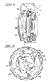
- a vehicle wheel comprises a circular wheel half 10 and a circular wheel half 12.
- Wheel half 10 has an inside rim part 14 and wheel half 12 has an outside rim part 16. Together, rim parts 14 and 16 form a rim adapted to receive a pneumatic tire 18, represented in phantom in FIG. 1.
- Wheel half 10 also has a circular hub 20 within rim part 14.
- Wheel half 12 also has an annular inwardly extending flange 22 within rim part 16. The periphery of hub 20 is recessed to receive flange 22 and to permit the central portion of hub 20 to fit snugly into the annular region surrounded by flange 22.
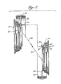
- the mating surfaces of flange 22 and the central portion of hub 20 are preferably tapered at a small angle to the central axis of the wheel, e.g., 3° as illustrated in FIG. 2.
- Wheel half 10 has threaded bolts 26 fixedly mounted in holes in the recessed periphery of hub 20 and extending therefrom parallel to the central axis of wheel half 10.
- Wheel half 12 has holes 25 aligned with bolts 26. Wheel halves 10 and 12 are releasably secured and clamped by nuts 27 screwed onto bolts 26, when they lie in holes 25 with flange 22 and hub 20 mated.
- a sealing ring 24, which could be made, for example, of neoprene rubber is bonded to the surface of flange 22 where it joins rim part 16.
- a sealing ring 24 which could be made, for example, of neoprene rubber is bonded to the surface of flange 22 where it joins rim part 16.
- An annular safety tread or foot 28 is divided circumferentially into approximately equal interfacing parts 30 and 32.
- Tread 28 has a larger diameter than the rim.
- Part 30 is attached to rim part 16 by a radially outward extending web 34 and part 32 is attached to rim part 14 by a radially outward extending web 36 so that webs 34 and 36 and parts 30 and 32 are aligned with each other when wheel halves 10 and 12 are secured together.
- Tread 28 has edges that are curved somewhat toward the edges of the wheel rim to increase the area of contact with a deflated tire. Webs 34 and 36 join rim parts 14 and 16 midway between the curved edges. In the embodiment of FIGS.
- rim part 14, hub 20, tread part 32, and web 34 are welded together or cast as a unit to form a one-piece construction.
- rim part 16, flange 22, tread part 30, and web 36 are welded together or cast as a unit to form a one-piece construction.
- Tread parts 30 and 32 interface with each other on a bias, as depicted in the drawings at 38, so that they can be brought together and separated by relative movement having a component transverse to the central axis of the wheel. In this way, after one rim part has been inserted into the tire casing, the other rim part can be slipped therein at an angle to the central axis of the wheel by wedging action between the interfaces of the foot parts.
- the bias of the interface on both sides of the wheel halves runs in the same direction, as depicted in FIG. 3.
- the right-hand edge of part 30, as viewed in FIG. 1 has a shorter circumferential length than the right-hand edge of part 32.
- the left-hand edge of part 30 has a longer circumferential length than the left-hand edge of part 32.
- Rubber treads 40 and 42 are bonded to the outer surface of parts 30 and 32, respectively, to prevent friction or slippage of the tire relative to the safety tread.
- wheel half 10 is first mounted on the vehicle by bolting hub 20 onto the brake drum of the vehicle.
- the lugs of the vehicle pass through holes 44 in hub 20.
- a tire is mounted on rim part 14 with part 32 inside the tire casing.
- wheel half 12 is brought toward wheel half 10 out of alignment with its central axis.
- tread 28 is a separate piece clamped between wheel halves 10 and 12.
- a plurality of threadless lugs 50 extend from hub 20 toward flange 22. Lugs 50 are arranged in a circle around bolts 26.
- web 36 has a plurality of bores for receiving respective lugs 50 on hub 20.
- web 34 has a plurality of bores for receiving the remaining lugs 50 on hub 20. Lugs 50 and bores 52 serve to properly position, i.e., center tread 28 on the wheel and hold it in place until assembly is complete.
- annular seal 54 such as for example neoprene rubber is secured to hub 20 between tread 28 and bolts 26 to prevent air leakage from the tire through the interface between hub 20 and flange 22.
- Holes 56 are formed in webs 34 and 36 to reduce the weight of tread 28.
- wheel half 10 may be placed on the ground, then the tire may be placed around wheel half 10.
- tread parts 30 and 32 are inserted into the interior of the tire so that bores 52 receive lugs 50.
- wheel half 12 is brought against webs 34 and 36 so holes 25 receive bolts 26 and nuts 27 are screwed onto bolts 26 in order to hold the parts of the wheel together.
- Safety tread 28 of FIGS. 4 and 5 which is not welded to the wheel, could alternatively be divided into three or four pieces, as tire mounting requirements may dictate.
Landscapes
- Engineering & Computer Science (AREA)
- Mechanical Engineering (AREA)
- Tires In General (AREA)
Claims (8)
Priority Applications (3)
| Application Number | Priority Date | Filing Date | Title |
|---|---|---|---|
| EP84100064A EP0147495B1 (de) | 1984-01-04 | 1984-01-04 | Kraftfahrzeugrad mit Notlauffläche |
| DE8484100064T DE3470705D1 (en) | 1984-01-04 | 1984-01-04 | Vehicle wheel having safety tread |
| AT84100064T ATE33795T1 (de) | 1984-01-04 | 1984-01-04 | Kraftfahrzeugrad mit notlaufflaeche. |
Applications Claiming Priority (1)
| Application Number | Priority Date | Filing Date | Title |
|---|---|---|---|
| EP84100064A EP0147495B1 (de) | 1984-01-04 | 1984-01-04 | Kraftfahrzeugrad mit Notlauffläche |
Publications (2)
| Publication Number | Publication Date |
|---|---|
| EP0147495A1 EP0147495A1 (de) | 1985-07-10 |
| EP0147495B1 true EP0147495B1 (de) | 1988-04-27 |
Family
ID=8191680
Family Applications (1)
| Application Number | Title | Priority Date | Filing Date |
|---|---|---|---|
| EP84100064A Expired EP0147495B1 (de) | 1984-01-04 | 1984-01-04 | Kraftfahrzeugrad mit Notlauffläche |
Country Status (3)
| Country | Link |
|---|---|
| EP (1) | EP0147495B1 (de) |
| AT (1) | ATE33795T1 (de) |
| DE (1) | DE3470705D1 (de) |
Families Citing this family (4)
| Publication number | Priority date | Publication date | Assignee | Title |
|---|---|---|---|---|
| GB8506181D0 (en) * | 1985-03-09 | 1985-04-11 | Sp Tyres Uk Ltd | Vehicle wheel |
| GB2189749A (en) * | 1986-05-01 | 1987-11-04 | Yi Jye Tony Shiah | Wheel rim for a run-flat pneumatic tyre |
| EP0490585A1 (de) * | 1990-12-07 | 1992-06-17 | Yng-Lang Lin | Fahrzeugrad mit Sicherheitsrad im Reifen |
| CN106218326A (zh) * | 2016-08-24 | 2016-12-14 | 天津东方兴泰工业科技股份有限公司 | 一种耐用型汽车轮毂 |
Family Cites Families (6)
| Publication number | Priority date | Publication date | Assignee | Title |
|---|---|---|---|---|
| DE972486C (de) * | 1950-06-23 | 1959-07-30 | Nicholas Peter Sorr Straussler | Schlauchloser Niederdruckluftreifen mit Notlaufflaeche |
| DE956380C (de) * | 1955-07-28 | 1957-01-17 | Continental Gummi Werke Ag | Fahrzeugrad mit einem Luftreifen, der sich beim Entweichen der Luft auf einem starren Teil des Radkoerpers abstuetzt |
| US3135556A (en) * | 1962-02-01 | 1964-06-02 | William L Lindley | Integral wheel, drum, and tire rim for a vehicle |
| NL6909616A (de) * | 1969-06-24 | 1970-12-29 | ||
| GB1439331A (en) * | 1972-09-08 | 1976-06-16 | Dunlop Ltd | Vehicle wheels |
| US3872907A (en) * | 1973-10-01 | 1975-03-25 | Goodyear Tire & Rubber | Safety support device for pneumatic tires |
-
1984
- 1984-01-04 DE DE8484100064T patent/DE3470705D1/de not_active Expired
- 1984-01-04 AT AT84100064T patent/ATE33795T1/de active
- 1984-01-04 EP EP84100064A patent/EP0147495B1/de not_active Expired
Also Published As
| Publication number | Publication date |
|---|---|
| ATE33795T1 (de) | 1988-05-15 |
| EP0147495A1 (de) | 1985-07-10 |
| DE3470705D1 (en) | 1988-06-01 |
Similar Documents
| Publication | Publication Date | Title |
|---|---|---|
| US4424842A (en) | Vehicle wheel having safety tread | |
| US4327791A (en) | Safety tire and wheel assembly | |
| US4505314A (en) | Wheel with tire bead locking ring | |
| US9333798B2 (en) | Vehicle wheel, running wheel, vehicle and method of assembling and disassembling vehicle wheel | |
| US5018795A (en) | Vehicle wheel made of composite material | |
| CN114786959A (zh) | 包括内部充气通道的轮、起落装置以及包括这种轮的飞行器 | |
| US5343920A (en) | Wheel assembly with flange securing and pressure relieving means | |
| US6109319A (en) | Run-flat support for pneumatic tired wheel | |
| US4144922A (en) | Wheel rim assembly for tubeless pneumatic tires | |
| US4043374A (en) | Wheel rim assembly and method for demounting a tire therefrom | |
| EP0147495A1 (de) | Kraftfahrzeugrad mit Notlauffläche | |
| US4299647A (en) | Tire retreading apparatus | |
| US4228840A (en) | Safety wheel | |
| US4241776A (en) | Tire and wheel assemblies | |
| CA1211694A (en) | Circumferential conduit means for inflating a closed torus tire | |
| US5636673A (en) | Composite wheel | |
| US4105254A (en) | Wheel with rim embraced by tire | |
| ES284186U (es) | Llanta de una pieza para una rueda de vehiculo provista de neumatico | |
| EP0311415A2 (de) | Fahrzeug mit Mitteln zur Ermöglichen der Fahrtfortsetzung im luftlosen Zustand | |
| EP0085705B1 (de) | Radfelge für schlauchlose reifen | |
| US4406316A (en) | Wheel and low air pressure tire combination | |
| GB2124983A (en) | Wheel and tyre | |
| KR102376078B1 (ko) | 타이어 휠 조립체 | |
| KR200182357Y1 (ko) | 타이어 안전장치 | |
| JPH0241902A (ja) | オフロトード用車輪 |
Legal Events
| Date | Code | Title | Description |
|---|---|---|---|
| PUAI | Public reference made under article 153(3) epc to a published international application that has entered the european phase |
Free format text: ORIGINAL CODE: 0009012 |
|
| AK | Designated contracting states |
Designated state(s): AT BE CH DE FR GB IT LI NL SE |
|
| 17P | Request for examination filed |
Effective date: 19851206 |
|
| 17Q | First examination report despatched |
Effective date: 19860917 |
|
| GRAA | (expected) grant |
Free format text: ORIGINAL CODE: 0009210 |
|
| AK | Designated contracting states |
Kind code of ref document: B1 Designated state(s): AT BE CH DE FR GB IT LI NL SE |
|
| PG25 | Lapsed in a contracting state [announced via postgrant information from national office to epo] |
Ref country code: NL Effective date: 19880427 Ref country code: LI Effective date: 19880427 Ref country code: IT Free format text: LAPSE BECAUSE OF FAILURE TO SUBMIT A TRANSLATION OF THE DESCRIPTION OR TO PAY THE FEE WITHIN THE PRESCRIBED TIME-LIMIT;WARNING: LAPSES OF ITALIAN PATENTS WITH EFFECTIVE DATE BEFORE 2007 MAY HAVE OCCURRED AT ANY TIME BEFORE 2007. THE CORRECT EFFECTIVE DATE MAY BE DIFFERENT FROM THE ONE RECORDED. Effective date: 19880427 Ref country code: CH Effective date: 19880427 Ref country code: BE Effective date: 19880427 Ref country code: AT Effective date: 19880427 |
|
| REF | Corresponds to: |
Ref document number: 33795 Country of ref document: AT Date of ref document: 19880515 Kind code of ref document: T |
|
| PG25 | Lapsed in a contracting state [announced via postgrant information from national office to epo] |
Ref country code: SE Effective date: 19880430 |
|
| REF | Corresponds to: |
Ref document number: 3470705 Country of ref document: DE Date of ref document: 19880601 |
|
| ET | Fr: translation filed | ||
| REG | Reference to a national code |
Ref country code: CH Ref legal event code: PL |
|
| NLV1 | Nl: lapsed or annulled due to failure to fulfill the requirements of art. 29p and 29m of the patents act | ||
| PG25 | Lapsed in a contracting state [announced via postgrant information from national office to epo] |
Ref country code: GB Effective date: 19890104 |
|
| PLBE | No opposition filed within time limit |
Free format text: ORIGINAL CODE: 0009261 |
|
| STAA | Information on the status of an ep patent application or granted ep patent |
Free format text: STATUS: NO OPPOSITION FILED WITHIN TIME LIMIT |
|
| 26N | No opposition filed | ||
| GBPC | Gb: european patent ceased through non-payment of renewal fee | ||
| PGFP | Annual fee paid to national office [announced via postgrant information from national office to epo] |
Ref country code: FR Payment date: 19911212 Year of fee payment: 9 |
|
| PGFP | Annual fee paid to national office [announced via postgrant information from national office to epo] |
Ref country code: DE Payment date: 19911218 Year of fee payment: 9 |
|
| PG25 | Lapsed in a contracting state [announced via postgrant information from national office to epo] |
Ref country code: FR Effective date: 19930930 |
|
| PG25 | Lapsed in a contracting state [announced via postgrant information from national office to epo] |
Ref country code: DE Effective date: 19931001 |
|
| REG | Reference to a national code |
Ref country code: FR Ref legal event code: ST |