EP0147248A2 - Réseau de câbles et filtres de couplage à pertes - Google Patents
Réseau de câbles et filtres de couplage à pertes Download PDFInfo
- Publication number
- EP0147248A2 EP0147248A2 EP84401657A EP84401657A EP0147248A2 EP 0147248 A2 EP0147248 A2 EP 0147248A2 EP 84401657 A EP84401657 A EP 84401657A EP 84401657 A EP84401657 A EP 84401657A EP 0147248 A2 EP0147248 A2 EP 0147248A2
- Authority
- EP
- European Patent Office
- Prior art keywords
- filter
- attenuation
- electromagnetic
- line
- losses
- Prior art date
- Legal status (The legal status is an assumption and is not a legal conclusion. Google has not performed a legal analysis and makes no representation as to the accuracy of the status listed.)
- Granted
Links
Images


Classifications
-
- H—ELECTRICITY
- H01—ELECTRIC ELEMENTS
- H01P—WAVEGUIDES; RESONATORS, LINES, OR OTHER DEVICES OF THE WAVEGUIDE TYPE
- H01P1/00—Auxiliary devices
- H01P1/20—Frequency-selective devices, e.g. filters
- H01P1/201—Filters for transverse electromagnetic waves
-
- H—ELECTRICITY
- H01—ELECTRIC ELEMENTS
- H01B—CABLES; CONDUCTORS; INSULATORS; SELECTION OF MATERIALS FOR THEIR CONDUCTIVE, INSULATING OR DIELECTRIC PROPERTIES
- H01B11/00—Communication cables or conductors
- H01B11/02—Cables with twisted pairs or quads
- H01B11/12—Arrangements for exhibiting specific transmission characteristics
-
- H—ELECTRICITY
- H03—ELECTRONIC CIRCUITRY
- H03H—IMPEDANCE NETWORKS, e.g. RESONANT CIRCUITS; RESONATORS
- H03H7/00—Multiple-port networks comprising only passive electrical elements as network components
Definitions
- wires and cables take advantage of magnetic and dielectric lesses of the conductor(s), the magnetic and dielectric absorption of the media surrounding this conductor(s), and one can realize low-pass lines, cables and filters having cut off frequencies (attenuation of 3 dB/m) of 20 MHz for straight conductor structures and 300 kHz for helical conductor structures. For frequencies above this range attenuation continues to increase and decreases occur only at frequencies above 2 to 40 GHz, where the magnetic effects disappear.
- a first aim of the invention is to extend the absorptive performance of the above-described wires/lines/cables/filters towards lower and towards higher frequencies.
- a second aim of the invention is to raise the attenuation of the described wires/lines/cables/filters, tor a given frequency, a typical example representing the simulated skin effect, described in my US-application N°429 032.
- Another typical example is the possibility to replace a complicated and expensive implementation (like a helical line), by a straight wire or cable, of simple structure, both less expensive and of lower weight : this fact may be important when the weight of the interconnection is limited, such as in air-borne or space applications.
- a third aim of the invention is to re-shape the attenuation curve of such a structure (in the frequency domain ), so as to achieve a desirable result : indeed, starting from the above- mentioned physical phenomena, difficult to control, one may desire to absorb certain frequency bands more and others less.
- a fourth aim of the invention consists of the concept of a new type of electrical network, where, with the'addition of dissimilar wire/line/cable elements, and/or the use of lumped electrical components, of the right value, and in the right location, one can optimize the desired results.
- electrical lines In order to explain better the principles of the invention, I recall some fundamentals relating to electrical lines - the term "electrical lines" is taken in a very general sense to include wires and cables, distributing electrical signals and/or electrical power, twisted cables, cables with common mode suppression, shielded cables, rigid lines of the printed circuit type and strip-lines, filters made out of these, etc.
- the square-root of this series impedance, divided by this shunt admittance, represents the characteristic impedance of the line, I.
- the square-root of their product represents the propagation constant, of which the real part is the attenuation ⁇ (in dB/m), which is to be optimized, according to the invention.
- the interconnection of low-loss electrical lines,' is generally made by characteristic impedance matching, i.e. connectors and lines have the same characteristic impedance all-over : consequently wave reflections are avoided at the interfaces : the wave becomes "progressive”, the"return-loss” is small, and the wave propagates with a minimum of losses.
- the incident wave is essentially reflected at the interface : before arriving at the other end of the structure the wave will have passed each element several times after multiple reflections.
- the wave will undergo a reflection equal to i.e. close to Z 01 /Z 02 in magnitude, if the discontinuity is significant-.
- the amplitude reduction (corresponding to this maximum of attenuation) is equal to
- the amplitude of the attenuation maxima may become much higher than the intrinsic losses of the elements : independantly from these intrinsic losses, this value represents the " mismatch losses” or “interfacial losses” according to the invention.
- the invention is based upon such a "multiplication" of the intrinsic attenuation of the elements.
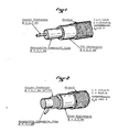
- the structure of the first cable is described in figure 1, in a coaxial implementation, where a copper-conductor is surrounded by the commercially known magnetic absorptive composite MUSORB. This composite is then covered by a thin insulating layer, and in turn by a classical conductive shielding braid. As a direct consequence of this, the cable uses a straight conductor with both a reduced distributed inductance and a high distributed capacitance relative to ground (due to the thin dielectric insulation and the high permittivity of the absorptive composite).
- the cable of figure 1 uses a copper conductor 1, of diameter 1,5 mm, with a surrounding absorptive composite 2 of diameter 5,5 mm, a PVC-layer 3 of diameter 6,5 mm and the shield 4.
- the distributed inductance L is 2,7 ⁇ H/m
- the distributed capacitance C is 1050pP/m
- this cable has a low characteristic impedance, which can be realized through many other methods, as is known in the art.
- the second cable shows a high characteristic impedance : a copper conductor 5, of diameter 0,3 mm is wound on a core of the same absorptive composite 6, of diameter 3 mm, with a pitch of 30 turns per sentimetre. A dielectric foam 7, of outer diameter of 6 mm is placed around the winding, and finally a conductive screen 8 is applied around the structure.
- the distributed inductance L is 310 ⁇ H/m
- the distributed capacitance' C is equal to 86 pF/m
- the characteristic impedance increases to Z 02 ⁇ 1900 ⁇ .
- This cable uses a helical conductor, achieving a high value of distributed inductance, and a reduced ground-capacitance, due to the dielectric foam insulation, with a relative permittivity close to one.
- this cable with a high value of characteristic impedance, can have many implementations, as known in the art.
- a straight conductor is desired, one can use a structure as shown in figure 1, with a low permittivity insulation, a thicker insulation, a magnetic surface conductor (raising the internal inductance), etc.
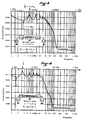
- test series results has been made with standard MIL-STD-220A test equipment, i.e. with a characteristic impedance of 50 ⁇ : in other words, the cable of figure 1 will be perfectly matched- On the other hand, the very dasign of the second cable, figure. 2, introduces mismatch losses; For this reason, fixed attenuations, of 10 dB each, are connected so as to avoid disturbance of the generator (G) and test receiver (SA).
- Figure 3 shows the attenuation vs frequency curve with the high-characteristic-impedance cable : one can see that the quarter-wavelength for the 0,52m length of the helical line corresponds to 3,6 MHz, basic attenuation of the line as shown by the dotted curve, is equal to approximately 1,4 dB at that frequency.
- the "half wavelength” corresponds to 7,2 MHz, and its multiples, with the expected attenuation minima.
- the amplitude of the fluctuations decreases with increasing frequency, and above 60 MHz approximately, no reflected wave can reach the output anymore.
- Figure 4 shows the results with the same helical line, but of double length, i.e. 1,05 m : one sees, that resonance frequencies are now halved, and the basic attenuation (corresponding to the dotted line of figure 3) has now doubled.
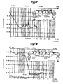
- Figure 5 shows two elements of the short helical line, separated by a "decoupling" element of the low impedance coaxial line, showing a minimum attenuation of several tenths of dB in the few MHz range .
- the total attenuation corresponds to the addtion of the attenuation of two cascaded helical line elements, plus the attenuation of the straight absorptive line : the attenuation at 3,6 MHz and its odd multiples has doubled (addition of the attenuation of two quarter-wavelengths), the even multiples showing minima at 7,14, ... MHz.
- the first slope, before the first quarter-wavelength is important in filter design : it can be placed anywhere one wishes within the absorptive spectrum of the lines, through the correct choice of the attenuation of the specific element (length of cable), in conjunction with the appropriate choice of the lengths of the quarter-wavelength elements.
- Magnetic and dielectric loss wires and cables as described in my US-patent application CIP-N°202654, maximise performance, as shown through these examples.
- the second case considered is the use of electrical lines interfaced with lumped components, shunt capacitors and/or series inductors, amongst others, introducing an impedance discontinuity.
- Curve a with the low-loss cable, shows clearly the reflection effects, due to the cable, and a typical increase of attenuation up to 30 MHz, the resonant frequency of the capacitors. Above 30MHz where the capacitors become inductive, they contribute little to the attenuation : interface reflections appear clearly, separated by 29 MHz - i.e. the half-wavelength of the length of the cable, as one can check easily, taking in account the relative permittivity of 3 of the dielectric. Such a high frequency attenuation is impractical for use as a filter.
- Curve.b corresponds to the implementation with the lossy cable of figure 1.
- the first quarter-wavelength, at 8,5 MHz shows up clearly; as well as the attenuation maximum at the capacitor's self-resonance. Above, the mismatch loss effect contributes to an overall attenuation superior to 60 dB, up to and above 10 GHz.
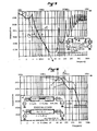
- Curve a shows the interfacial losses (with a first quarter-wavelength resonance at 160 MHz approximately), due to the discontinuity with the 50 ⁇ test-circuit impedance.
- Curve b) shows the mismatch losses (with a first quarter-wavelength.resonance at 45 MHz), i.e. approximately a third, which is due to the fact that the 100 ⁇ line segment is three times 'the length of the conductor in curve a).
- the line element with characteristic impedance discontinuities consists of a small coaxial component, which may be placed in the inner bore of an automotive spark-plug.
- Curve a) shows the measured attenuation with a semi-conductive layer resistor of 10 K ⁇ , a classical component used for ignition-interference suppression in the USA. The curve serves as reference, so as to show the vastly improved performance possible, in the useful 30 MHz to 1 GHz frequency range (SAE standard J 551).
- Curve b) shows a classical inductor, on a ceramic core, used too as a high volume suppressor item in the USA.: one can see clearly the numerous interface resonances (with ⁇ /4 ⁇ 25 MHz) - resonances which are barely damped, as this inductor has very low losses. ,
- Curve c) corresponds to an inductor of 170 ⁇ H, wound .with less turns than the inductor in.b) around an absorptive magnetic core, using the composites described earlier. Resonances are heavily damped, and one can see clearly the superimposition of the self-resonance of the inductor (compare with figure 9 and the above text describing a series inductor, with its self-resonance).
- the inductor c) shows a distinctive improvement in the RFI-attenuation, resulting in less conducted and radiated ignition-interference
- This type of distributed spark plug inductor can, of course, be an integral part of the ignition wire, as an extension of the spark-plug circuit.
- a segment of high characteristic impedance cable is placed, for example, at both ends of the ignition wire, i.e. close to the RFI sources (the spark plug and distributor sparks), each of them representing, for example, quarter-wavelengths for one or two selected frequencies, where an attenuation pole is desirable, as, for example,at 30 MHz, the lowest frequency to be suppressed, of the CISPR spectrum; the central part of the cable showing a reduced characteristic impedance, and representing the decoupling line segment.
- Figures 4 and 2 describe the design of two such lines to achieve a significant discontinuity of characteristic impedance :
- variants can thus be conceived, which can be manufactured by continuous extrusion process, with a double injection head, with winding machines with controlled ; advance of the core, etc.
- Other variants maybe processed with the ; inclusion, during automatic manufacture, of quasi-lumped cores,. washers, fialfsegments etc, of appropriate electrical and/or magnetic characteristics, similar to the manufacturing of certain coaxial cables, where the centre conductor is kept in place, by intervals, by dielectric washers.
- the first aspect of the invention describes the possibility to design lossy filters, by assembling of different lines and lengths, or by a continuous manufacturing process.
- a further subject to be considered is the case of different lines, in a network, with multiple interconnections. This is the case, for example, in the internal wiring of an electronic apparatus,-instrument, or, on a higher level, the wiring of a system, on a'ship, a plane, a satellite etc, where electro- magnetic compatibility is to be achieved to protect against various phenomena such as EMP.
- a third subject to be considered is the case of an industrial power distribution network, with uniform wire/cable segments, but with different impedances and/or with correctly placed. lumped impedances, in the network.
- the longer lengths of the wires/cables of the network allow the implementation of lower cut-off frequencies, and,possibly, as low as the frequency harmonics of the power supply itself : the interest for harmonic suppression due to electronic commutation for example DC-motors, due to semiconductor power-switching (Triacs, etc) is evident.
- Figure 12 shows an example of the implementation of the invention, in a uniform low-pass power distribution line.
- the low-pass line alone, for a 20 m length, shows a 20 dB attenuation for about 10 MHz - the addition of a lumped 22 nF capacitor at each end, gives the networks a 20 dB attenuation for a frequency as low as 1 MHz.
- the application to electrical train overhead power lines and high-voltage power lines is possible , where greater line lengths are used with the corresponding possibilities of increased attenuation.
- the implementation of characteristic impedance discontinuity is limited to the addition of certain lumped components, to the variation of ground (and inter- wire) capacity, and to variations of distributed series inductance : the artificial skin effect in my US-patent N°3573676 is a typical method to introduce simultaneously the required minimum loss as well as the characteristic impedance discontinuity.
- Such wave propagating structures may be open or closed (the above- mentioned hook-up wire close to ground, or the coaxial line); they may be symmetrical or dissymetrical (for example; twinaxial cable, twisted pair, etc), they may be straight or helical.
- the low-pass function may be applied separately to the differential mode (example: coaxial cable) or to the common mode (for example: common mode suppressor cable, where the absorptive function is achieved at the external side of a coaxial line,etc), or mixed structures with selected absorption of the two modes - as described for example in my US-patent application N°351 493.
- the interfacial loss effect described can be used to increase the absorption in the frequency range where the applied physical loss-effects decrease for increasing frequencies : this is the case above 5 to 50 GHz, which is dependant on the particular magnetic/dielectric materials used.
Landscapes
- Physics & Mathematics (AREA)
- Electromagnetism (AREA)
- Filters And Equalizers (AREA)
- Control Of Motors That Do Not Use Commutators (AREA)
- Input Circuits Of Receivers And Coupling Of Receivers And Audio Equipment (AREA)
- Communication Cables (AREA)
- Use Of Switch Circuits For Exchanges And Methods Of Control Of Multiplex Exchanges (AREA)
- Cable Transmission Systems, Equalization Of Radio And Reduction Of Echo (AREA)
- Superconductors And Manufacturing Methods Therefor (AREA)
- Organic Insulating Materials (AREA)
Priority Applications (1)
| Application Number | Priority Date | Filing Date | Title |
|---|---|---|---|
| AT84401657T ATE75081T1 (de) | 1983-08-10 | 1984-08-09 | Leitungskreise und filter mit kopplungsverlusten. |
Applications Claiming Priority (2)
| Application Number | Priority Date | Filing Date | Title |
|---|---|---|---|
| FR8313145 | 1983-08-10 | ||
| FR8313145A FR2550657B3 (fr) | 1983-08-10 | 1983-08-10 | Reseaux a cables et filtres a pertes interfaciales |
Publications (3)
| Publication Number | Publication Date |
|---|---|
| EP0147248A2 true EP0147248A2 (fr) | 1985-07-03 |
| EP0147248A3 EP0147248A3 (en) | 1986-11-05 |
| EP0147248B1 EP0147248B1 (fr) | 1992-04-15 |
Family
ID=9291536
Family Applications (1)
| Application Number | Title | Priority Date | Filing Date |
|---|---|---|---|
| EP84401657A Expired - Lifetime EP0147248B1 (fr) | 1983-08-10 | 1984-08-09 | Réseau de câbles et filtres de couplage à pertes |
Country Status (5)
| Country | Link |
|---|---|
| EP (1) | EP0147248B1 (fr) |
| AT (1) | ATE75081T1 (fr) |
| CA (1) | CA1223929A (fr) |
| DE (1) | DE3485659D1 (fr) |
| FR (1) | FR2550657B3 (fr) |
-
1983
- 1983-08-10 FR FR8313145A patent/FR2550657B3/fr not_active Expired
-
1984
- 1984-08-09 AT AT84401657T patent/ATE75081T1/de not_active IP Right Cessation
- 1984-08-09 DE DE8484401657T patent/DE3485659D1/de not_active Expired - Lifetime
- 1984-08-09 EP EP84401657A patent/EP0147248B1/fr not_active Expired - Lifetime
- 1984-08-10 CA CA000460803A patent/CA1223929A/fr not_active Expired
Non-Patent Citations (2)
| Title |
|---|
| IEEE TRANSACTIONS ON ELECTROMAGNETIC COMPATIBILITY, vol. EMC-18, no. 2, May 1976, pages 59-70; F. MAYER: "RFI suppression components: State of the art; new developments" * |
| P. GRIVET: "Physique des lignes de haute fréquence et d'ultra-haute fréquence", 1969, pages 25-67, Masson & Cie, Paris, FR; "Tome I: Paramètres primaires et secondaires ondes progressives impulsions" * |
Also Published As
| Publication number | Publication date |
|---|---|
| CA1223929A (fr) | 1987-07-07 |
| ATE75081T1 (de) | 1992-05-15 |
| EP0147248A3 (en) | 1986-11-05 |
| EP0147248B1 (fr) | 1992-04-15 |
| DE3485659D1 (de) | 1992-05-21 |
| FR2550657A1 (fr) | 1985-02-15 |
| FR2550657B3 (fr) | 1987-02-27 |
Similar Documents
| Publication | Publication Date | Title |
|---|---|---|
| US4683450A (en) | Line with distributed low-pass filter section wherein spurious signals are attenuated | |
| US3786372A (en) | Broadband high frequency balun | |
| US5321373A (en) | Combined differential-mode common-mode noise filter | |
| US3970969A (en) | Device for the electrical protection of a coaxial cable by two connected circuits | |
| US20140232505A1 (en) | Coil structure and electronic device | |
| JP3350792B2 (ja) | 平行ストリップラインケーブル | |
| JPH1092233A (ja) | 電磁妨害から保護される電気信号伝送装置 | |
| US4104600A (en) | Integrated absorptive power line filters | |
| US6246310B1 (en) | Noise suppressing apparatus | |
| JPH09321482A (ja) | ライン放射防止素子 | |
| WO2017056097A1 (fr) | Appareil et procédé de suppression de bruit de mode commun | |
| US3716806A (en) | Signal coupling apparatus utilizing hybrid transformer | |
| JP2001503201A (ja) | インダクタ | |
| Balanis | Circular waveguides | |
| EP0147248B1 (fr) | Réseau de câbles et filtres de couplage à pertes | |
| JP3863674B2 (ja) | コモンモードフィルタ | |
| Mayer | Absorptive low-pass cables: state of the art and an outlook to the future | |
| JP3029198B1 (ja) | 接地用電線 | |
| US10931067B2 (en) | Common mode choke | |
| RU2650421C2 (ru) | Малогабаритный направленный ответвитель | |
| Wada et al. | Basic characteristics of a quarter-wavelength CPW resonator with tap-feed structure and its application to a bandpass filter with attenuation poles | |
| US6529091B2 (en) | Absorptive circuit element, absorptive low-pass filter and manufacturing method of the filter | |
| RU2327261C2 (ru) | Полосно-заграждающий фильтр | |
| Shiraki et al. | High performance broadband noise filter using inductance cancellation technique and various capacitors | |
| JP5519947B2 (ja) | 帯域通過フィルタ |
Legal Events
| Date | Code | Title | Description |
|---|---|---|---|
| PUAI | Public reference made under article 153(3) epc to a published international application that has entered the european phase |
Free format text: ORIGINAL CODE: 0009012 |
|
| AK | Designated contracting states |
Designated state(s): AT BE CH DE FR GB IT LI LU NL SE |
|
| PUAL | Search report despatched |
Free format text: ORIGINAL CODE: 0009013 |
|
| AK | Designated contracting states |
Kind code of ref document: A3 Designated state(s): AT BE CH DE FR GB IT LI LU NL SE |
|
| 17P | Request for examination filed |
Effective date: 19870629 |
|
| 17Q | First examination report despatched |
Effective date: 19891228 |
|
| GRAA | (expected) grant |
Free format text: ORIGINAL CODE: 0009210 |
|
| AK | Designated contracting states |
Kind code of ref document: B1 Designated state(s): AT BE CH DE FR GB IT LI LU NL SE |
|
| PG25 | Lapsed in a contracting state [announced via postgrant information from national office to epo] |
Ref country code: SE Effective date: 19920415 Ref country code: NL Effective date: 19920415 Ref country code: LI Effective date: 19920415 Ref country code: IT Free format text: LAPSE BECAUSE OF FAILURE TO SUBMIT A TRANSLATION OF THE DESCRIPTION OR TO PAY THE FEE WITHIN THE PRESCRIBED TIME-LIMIT;WARNING: LAPSES OF ITALIAN PATENTS WITH EFFECTIVE DATE BEFORE 2007 MAY HAVE OCCURRED AT ANY TIME BEFORE 2007. THE CORRECT EFFECTIVE DATE MAY BE DIFFERENT FROM THE ONE RECORDED. Effective date: 19920415 Ref country code: CH Effective date: 19920415 Ref country code: BE Effective date: 19920415 Ref country code: AT Effective date: 19920415 |
|
| REF | Corresponds to: |
Ref document number: 75081 Country of ref document: AT Date of ref document: 19920515 Kind code of ref document: T |
|
| REF | Corresponds to: |
Ref document number: 3485659 Country of ref document: DE Date of ref document: 19920521 |
|
| REG | Reference to a national code |
Ref country code: CH Ref legal event code: PL |
|
| PG25 | Lapsed in a contracting state [announced via postgrant information from national office to epo] |
Ref country code: GB Effective date: 19920809 |
|
| ET | Fr: translation filed | ||
| PG25 | Lapsed in a contracting state [announced via postgrant information from national office to epo] |
Ref country code: LU Free format text: LAPSE BECAUSE OF NON-PAYMENT OF DUE FEES Effective date: 19920831 |
|
| NLV1 | Nl: lapsed or annulled due to failure to fulfill the requirements of art. 29p and 29m of the patents act | ||
| PLBE | No opposition filed within time limit |
Free format text: ORIGINAL CODE: 0009261 |
|
| STAA | Information on the status of an ep patent application or granted ep patent |
Free format text: STATUS: NO OPPOSITION FILED WITHIN TIME LIMIT |
|
| 26N | No opposition filed | ||
| GBPC | Gb: european patent ceased through non-payment of renewal fee |
Effective date: 19920809 |
|
| PGFP | Annual fee paid to national office [announced via postgrant information from national office to epo] |
Ref country code: DE Payment date: 19950811 Year of fee payment: 12 |
|
| PGFP | Annual fee paid to national office [announced via postgrant information from national office to epo] |
Ref country code: FR Payment date: 19960730 Year of fee payment: 13 |
|
| PG25 | Lapsed in a contracting state [announced via postgrant information from national office to epo] |
Ref country code: DE Effective date: 19970501 |
|
| PG25 | Lapsed in a contracting state [announced via postgrant information from national office to epo] |
Ref country code: FR Free format text: LAPSE BECAUSE OF NON-PAYMENT OF DUE FEES Effective date: 19980430 |
|
| REG | Reference to a national code |
Ref country code: FR Ref legal event code: ST |