EP0147228A2 - Système de commande du moment de torsion d'un embrayage électromagnétique d'un véhicule - Google Patents
Système de commande du moment de torsion d'un embrayage électromagnétique d'un véhicule Download PDFInfo
- Publication number
- EP0147228A2 EP0147228A2 EP84309074A EP84309074A EP0147228A2 EP 0147228 A2 EP0147228 A2 EP 0147228A2 EP 84309074 A EP84309074 A EP 84309074A EP 84309074 A EP84309074 A EP 84309074A EP 0147228 A2 EP0147228 A2 EP 0147228A2
- Authority
- EP
- European Patent Office
- Prior art keywords
- clutch
- output signal
- switch
- pulse train
- circuit
- Prior art date
- Legal status (The legal status is an assumption and is not a legal conclusion. Google has not performed a legal analysis and makes no representation as to the accuracy of the status listed.)
- Granted
Links
- 230000000994 depressogenic effect Effects 0.000 claims abstract description 10
- 230000007423 decrease Effects 0.000 claims abstract description 5
- 230000005540 biological transmission Effects 0.000 description 10
- 239000000843 powder Substances 0.000 description 6
- 230000035939 shock Effects 0.000 description 4
- 239000003990 capacitor Substances 0.000 description 2
- 230000004907 flux Effects 0.000 description 2
- 206010017577 Gait disturbance Diseases 0.000 description 1
- 230000001133 acceleration Effects 0.000 description 1
- 230000003247 decreasing effect Effects 0.000 description 1
- 230000001419 dependent effect Effects 0.000 description 1
- 238000010586 diagram Methods 0.000 description 1
- 230000001788 irregular Effects 0.000 description 1
- 239000000696 magnetic material Substances 0.000 description 1
- 239000006247 magnetic powder Substances 0.000 description 1
- 230000004048 modification Effects 0.000 description 1
- 238000012986 modification Methods 0.000 description 1
- 230000000630 rising effect Effects 0.000 description 1
Images


Classifications
-
- F—MECHANICAL ENGINEERING; LIGHTING; HEATING; WEAPONS; BLASTING
- F16—ENGINEERING ELEMENTS AND UNITS; GENERAL MEASURES FOR PRODUCING AND MAINTAINING EFFECTIVE FUNCTIONING OF MACHINES OR INSTALLATIONS; THERMAL INSULATION IN GENERAL
- F16D—COUPLINGS FOR TRANSMITTING ROTATION; CLUTCHES; BRAKES
- F16D48/00—External control of clutches
- F16D48/06—Control by electric or electronic means, e.g. of fluid pressure
- F16D48/064—Control of electrically or electromagnetically actuated clutches
-
- B—PERFORMING OPERATIONS; TRANSPORTING
- B60—VEHICLES IN GENERAL
- B60W—CONJOINT CONTROL OF VEHICLE SUB-UNITS OF DIFFERENT TYPE OR DIFFERENT FUNCTION; CONTROL SYSTEMS SPECIALLY ADAPTED FOR HYBRID VEHICLES; ROAD VEHICLE DRIVE CONTROL SYSTEMS FOR PURPOSES NOT RELATED TO THE CONTROL OF A PARTICULAR SUB-UNIT
- B60W2710/00—Output or target parameters relating to a particular sub-units
- B60W2710/02—Clutches
- B60W2710/021—Clutch engagement state
- B60W2710/023—Clutch engagement rate
-
- F—MECHANICAL ENGINEERING; LIGHTING; HEATING; WEAPONS; BLASTING
- F16—ENGINEERING ELEMENTS AND UNITS; GENERAL MEASURES FOR PRODUCING AND MAINTAINING EFFECTIVE FUNCTIONING OF MACHINES OR INSTALLATIONS; THERMAL INSULATION IN GENERAL
- F16D—COUPLINGS FOR TRANSMITTING ROTATION; CLUTCHES; BRAKES
- F16D2500/00—External control of clutches by electric or electronic means
- F16D2500/10—System to be controlled
- F16D2500/102—Actuator
- F16D2500/1021—Electrical type
- F16D2500/1022—Electromagnet
-
- F—MECHANICAL ENGINEERING; LIGHTING; HEATING; WEAPONS; BLASTING
- F16—ENGINEERING ELEMENTS AND UNITS; GENERAL MEASURES FOR PRODUCING AND MAINTAINING EFFECTIVE FUNCTIONING OF MACHINES OR INSTALLATIONS; THERMAL INSULATION IN GENERAL
- F16D—COUPLINGS FOR TRANSMITTING ROTATION; CLUTCHES; BRAKES
- F16D2500/00—External control of clutches by electric or electronic means
- F16D2500/10—System to be controlled
- F16D2500/104—Clutch
- F16D2500/10406—Clutch position
- F16D2500/10412—Transmission line of a vehicle
-
- F—MECHANICAL ENGINEERING; LIGHTING; HEATING; WEAPONS; BLASTING
- F16—ENGINEERING ELEMENTS AND UNITS; GENERAL MEASURES FOR PRODUCING AND MAINTAINING EFFECTIVE FUNCTIONING OF MACHINES OR INSTALLATIONS; THERMAL INSULATION IN GENERAL
- F16D—COUPLINGS FOR TRANSMITTING ROTATION; CLUTCHES; BRAKES
- F16D2500/00—External control of clutches by electric or electronic means
- F16D2500/30—Signal inputs
- F16D2500/314—Signal inputs from the user
- F16D2500/31406—Signal inputs from the user input from pedals
- F16D2500/3144—Accelerator pedal position
- F16D2500/31453—Accelerator pedal position threshold, e.g. switch
-
- F—MECHANICAL ENGINEERING; LIGHTING; HEATING; WEAPONS; BLASTING
- F16—ENGINEERING ELEMENTS AND UNITS; GENERAL MEASURES FOR PRODUCING AND MAINTAINING EFFECTIVE FUNCTIONING OF MACHINES OR INSTALLATIONS; THERMAL INSULATION IN GENERAL
- F16D—COUPLINGS FOR TRANSMITTING ROTATION; CLUTCHES; BRAKES
- F16D2500/00—External control of clutches by electric or electronic means
- F16D2500/50—Problem to be solved by the control system
- F16D2500/502—Relating the clutch
- F16D2500/50239—Soft clutch engagement
-
- F—MECHANICAL ENGINEERING; LIGHTING; HEATING; WEAPONS; BLASTING
- F16—ENGINEERING ELEMENTS AND UNITS; GENERAL MEASURES FOR PRODUCING AND MAINTAINING EFFECTIVE FUNCTIONING OF MACHINES OR INSTALLATIONS; THERMAL INSULATION IN GENERAL
- F16D—COUPLINGS FOR TRANSMITTING ROTATION; CLUTCHES; BRAKES
- F16D2500/00—External control of clutches by electric or electronic means
- F16D2500/50—Problem to be solved by the control system
- F16D2500/502—Relating the clutch
- F16D2500/50287—Torque control
- F16D2500/5029—Reducing drag torque
-
- F—MECHANICAL ENGINEERING; LIGHTING; HEATING; WEAPONS; BLASTING
- F16—ENGINEERING ELEMENTS AND UNITS; GENERAL MEASURES FOR PRODUCING AND MAINTAINING EFFECTIVE FUNCTIONING OF MACHINES OR INSTALLATIONS; THERMAL INSULATION IN GENERAL
- F16D—COUPLINGS FOR TRANSMITTING ROTATION; CLUTCHES; BRAKES
- F16D2500/00—External control of clutches by electric or electronic means
- F16D2500/70—Details about the implementation of the control system
- F16D2500/702—Look-up tables
- F16D2500/70252—Clutch torque
- F16D2500/70282—Time
-
- F—MECHANICAL ENGINEERING; LIGHTING; HEATING; WEAPONS; BLASTING
- F16—ENGINEERING ELEMENTS AND UNITS; GENERAL MEASURES FOR PRODUCING AND MAINTAINING EFFECTIVE FUNCTIONING OF MACHINES OR INSTALLATIONS; THERMAL INSULATION IN GENERAL
- F16D—COUPLINGS FOR TRANSMITTING ROTATION; CLUTCHES; BRAKES
- F16D2500/00—External control of clutches by electric or electronic means
- F16D2500/70—Details about the implementation of the control system
- F16D2500/704—Output parameters from the control unit; Target parameters to be controlled
- F16D2500/70402—Actuator parameters
- F16D2500/70418—Current
-
- F—MECHANICAL ENGINEERING; LIGHTING; HEATING; WEAPONS; BLASTING
- F16—ENGINEERING ELEMENTS AND UNITS; GENERAL MEASURES FOR PRODUCING AND MAINTAINING EFFECTIVE FUNCTIONING OF MACHINES OR INSTALLATIONS; THERMAL INSULATION IN GENERAL
- F16D—COUPLINGS FOR TRANSMITTING ROTATION; CLUTCHES; BRAKES
- F16D2500/00—External control of clutches by electric or electronic means
- F16D2500/70—Details about the implementation of the control system
- F16D2500/704—Output parameters from the control unit; Target parameters to be controlled
- F16D2500/70402—Actuator parameters
- F16D2500/7042—Voltage
-
- F—MECHANICAL ENGINEERING; LIGHTING; HEATING; WEAPONS; BLASTING
- F16—ENGINEERING ELEMENTS AND UNITS; GENERAL MEASURES FOR PRODUCING AND MAINTAINING EFFECTIVE FUNCTIONING OF MACHINES OR INSTALLATIONS; THERMAL INSULATION IN GENERAL
- F16D—COUPLINGS FOR TRANSMITTING ROTATION; CLUTCHES; BRAKES
- F16D2500/00—External control of clutches by electric or electronic means
- F16D2500/70—Details about the implementation of the control system
- F16D2500/704—Output parameters from the control unit; Target parameters to be controlled
- F16D2500/70422—Clutch parameters
- F16D2500/70438—From the output shaft
- F16D2500/7044—Output shaft torque
-
- F—MECHANICAL ENGINEERING; LIGHTING; HEATING; WEAPONS; BLASTING
- F16—ENGINEERING ELEMENTS AND UNITS; GENERAL MEASURES FOR PRODUCING AND MAINTAINING EFFECTIVE FUNCTIONING OF MACHINES OR INSTALLATIONS; THERMAL INSULATION IN GENERAL
- F16D—COUPLINGS FOR TRANSMITTING ROTATION; CLUTCHES; BRAKES
- F16D2500/00—External control of clutches by electric or electronic means
- F16D2500/70—Details about the implementation of the control system
- F16D2500/71—Actions
- F16D2500/7107—Others
- F16D2500/7109—Pulsed signal; Generating or processing pulsed signals; PWM, width modulation, frequency or amplitude modulation
Definitions
- the present invention relates to a system for controlling the clutch torque of an electromagnetic clutch disposed between an engine and a transmission of a motor vehicle, and more particularly to such a system which controls the variation of the clutch torque from a low clutch torque while an accelerator pedal is released to a high clutch torque when the pedal is depressed.
- Japanese Patent Publication No. 57-30624 discloses a clutch control system, in which clutch torque is maintained at a value larger than the engine torque by passing a rated current through the clutch coil, as long as the vehicle is driven faster than a predetermined speed, irrespective of the condition of the accelerator pedal.
- clutch torque is maintained at a value larger than the engine torque by passing a rated current through the clutch coil, as long as the vehicle is driven faster than a predetermined speed, irrespective of the condition of the accelerator pedal.
- irregular and abrupt fluctuations occur in engine torque and those fluctuations are transmitted to the driving system, giving an unpleasant shock to the driver.
- the level of the rated current needed to be supplied to the clutch at the lower engine speed while the acceleration pedal is released is high, the power of the vehicle battery is rapidly dissipated.
- An object of the present invention is to provide a clutch torque control system for an electromagnetic clutch which is capable of quickly increasing the engine speed in accordance with the depression of an. accelerator pedal and reduce the shock in transmission system by gradually engaging the clutch when the accelerator pedal is depressed.
- a system for controlling the clutch torque of an electromagnetic clutch of a vehicle having an accelerator pedal comprises an accelerator switch for producing a given output signal when the accelerator pedal is depressed, and a first circuit which includes a switching means and which is arranged to control the clutch current passing through a coil of the electromagnetic clutch.
- the invention is characterised in that a second circuit is responsive to the given output signal of the accelerator switch for controlling the switching means so as to decrease the clutch current to a low value and thereafter to increase the current gradually to a predetermined value.
- the switching means is preferably a transistor provided in the circuit of the clutch coil, and the second circuit may comprise a logic gate circuit and a pulse train generating circuit responsive to the given output signal of the accelerator switch for producing a pulse train controlled by the logic gate circuit, the duty ratio of the pulse train gradually varying so as to increase gradually the clutch current.
- an electromagnetic powder clutch 1 is interposed between an engine 2 of a vehicle and a transmission 3, which may be a manual gearbox or a belt-drive infinitely variable transmission and transmits the engine torque to the vehicle wheels.
- the electromagnetic powder clutch 1 comprises a drive member 7 connected to a crankshaft 4 of the engine 2 through a drive plate 5, a coil 6 provided in the drive member 7, a driven member 9 having its outer periphery spaced from the inner periphery of the drive member 7 by a gap 10, and a powder chamber 11 defined between the drive member 7 and driven member 9.
- the powder chamber 11 is filled with powder of magnetic material.
- the driven member 9 is secured to an input shaft 8 of the belt-drive infinitely variable transmission 3.
- a holder 12 secured to the drive membe-r 7 carries slip rings 13 which are electrically connected to the coil 6.
- the coil 6 is supplied through brushes 14 and slip rings 13 with a clutch current from a control unit 21.
- the transmission ratio is determined in dependence on the engine speed and the vehicle speed. When the vehicle speed is lower than a predetermined low value, the transmission ratio is at the. highest ratio. When the engine speed is at high value, the transmission ratio becomes low.
- An accelerator pedal switch 15 for detecting the depression of an accelerator pedal 15a is turned off to produce a high level output (a) when the pedal 15a is depressed, and is turned on to produce a low level output when the pedal is released.
- a vehicle speed switch 16 is turned on to produce a low level output when the vehicle speed exceeds a predetermined level, the output otherwise being at high level.
- the vehicle speed switch 16 and a start-control circuit 17 are connected to an AND gate 18 in the control unit 21; the output of AND gate 18 is applied to a driving transistor 20 through an OR gate 19 to control the clutch current passing through the clutch coil 6.
- the output (a) of the accelerator pedal switch 15 is connected to a NOR gate 23, AND gate 29 and, through an inverter 25 to a reference voltage generator 26.
- the output of a triangle generator 27 and the output of the reference voltage generator 26 are connected to the inputs of a comparator 28, the output of which is connected to the AND gate 29.
- the NOR gate 23 is supplied with a rectangular wave pulse train from an oscillator 22.
- the outputs (b, f) of NOR gate 23 and AND gate 29 are applied to an OR gate 24, the output (g) of which is applied to an AND gate 31.
- the output of the vehicle speed switch 16 is also applied to AND gate 31 through an inverter 30.
- the output of AND gate 31 is connected to the'other input of the OR gate 19.
- the reference voltage generator 26 comprises a transistor 32 which is turned on and off in response to the level of the output (a) of the accelerator switch 15.
- the switch 15 When the accelerator pedal is released, the switch 15 is turned on, so that the transistor 32 is turned on in response to the high level signal from the inverter 25.
- the reference voltage is set to a low value by the discharge of a capacitor 33.
- the transistor 28 When the transistor 28 is turned off, the reference voltage rises gradually with the charging of the capacitor 33 and reaches a high value which is higher than the peak voltage of the triangular pulses from the triangular generator 27.
- AND gate 29 is closed and NOR gate 23 produces a pulse train (b) as shown in Figure 2(b).
- the pulses b are fed to the transistor 20 through OR gate 24, _AND gate 31 and OR gate 19.
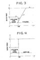
- clutch current dependent on the duty ratio of the pulse train (b) flows in the clutch coil 6, producing a low clutch torque T 1 as shown by a line 1 in Figure 3.
- the level of the output from the accelerator switch 15 goes to high level as shown in Figure 2(a), so that the output of the NOR gate 23 changes to low level. Therefore, only the output of the comparator 28 is supplied to the transistor 20 through AND gate 29, OR gate 24, AND gate 31 and OR gate 19.
- the comparator 28 compares the triangular wave pulse train (c) with the reference voltage (d) to produce a rectangular pulse train (e).
- the duty ratio of the pulse train (e) increases with the increase of the reference voltage (d) as shown in Figure 2(e) and (f).
- the clutch torque gradually increases as shown by a line l 3 in Figure 3, as the duty ratio of clutch current gradually increases.
- the duty ratio ultimately reaches-"1" when the rated current flows through the clutch coil.
- the rated clutch torque (lock-up torque) T 2 is provided as shown by a line l 4 .
- the clutch is then fully engaged to drive the vehicle.
- the above described operation can also be carried out by a micro-computer system.
Landscapes
- Physics & Mathematics (AREA)
- Engineering & Computer Science (AREA)
- General Engineering & Computer Science (AREA)
- Electromagnetism (AREA)
- Fluid Mechanics (AREA)
- Mechanical Engineering (AREA)
- Hydraulic Clutches, Magnetic Clutches, Fluid Clutches, And Fluid Joints (AREA)
- Arrangement And Mounting Of Devices That Control Transmission Of Motive Force (AREA)
Applications Claiming Priority (2)
| Application Number | Priority Date | Filing Date | Title |
|---|---|---|---|
| JP251024/83 | 1983-12-27 | ||
| JP58251024A JPS60139534A (ja) | 1983-12-27 | 1983-12-27 | 車両用電磁式クラツチのクラツチトルク制御装置 |
Publications (3)
| Publication Number | Publication Date |
|---|---|
| EP0147228A2 true EP0147228A2 (fr) | 1985-07-03 |
| EP0147228A3 EP0147228A3 (en) | 1985-08-07 |
| EP0147228B1 EP0147228B1 (fr) | 1988-04-20 |
Family
ID=17216485
Family Applications (1)
| Application Number | Title | Priority Date | Filing Date |
|---|---|---|---|
| EP84309074A Expired EP0147228B1 (fr) | 1983-12-27 | 1984-12-21 | Système de commande du moment de torsion d'un embrayage électromagnétique d'un véhicule |
Country Status (4)
| Country | Link |
|---|---|
| US (1) | US4660699A (fr) |
| EP (1) | EP0147228B1 (fr) |
| JP (1) | JPS60139534A (fr) |
| DE (2) | DE147228T1 (fr) |
Cited By (3)
| Publication number | Priority date | Publication date | Assignee | Title |
|---|---|---|---|---|
| EP0242127A2 (fr) * | 1986-04-09 | 1987-10-21 | Fuji Jukogyo Kabushiki Kaisha | Système pour commander l'embrayage d'un véhicule |
| WO1989003318A1 (fr) * | 1987-10-07 | 1989-04-20 | Automotive Products Plc | Commande d'embrayage |
| WO1990013756A1 (fr) * | 1989-05-08 | 1990-11-15 | The Foxboro Company | Coupleur pour demarrages en douceur |
Families Citing this family (4)
| Publication number | Priority date | Publication date | Assignee | Title |
|---|---|---|---|---|
| JPH0647352B2 (ja) * | 1985-08-02 | 1994-06-22 | トヨタ自動車株式会社 | 車両用磁粉式電磁クラツチの制御装置 |
| US4873637A (en) * | 1988-02-10 | 1989-10-10 | Eaton Corporation | Control for vehicle start from stop operation |
| US5094333A (en) * | 1990-02-07 | 1992-03-10 | Mitsubishi Denki K.K. | Current control device for an automotive electromagnetic clutch |
| US10012276B2 (en) * | 2014-06-24 | 2018-07-03 | Sri International | System and method for electrically controllable transmissions |
Citations (7)
| Publication number | Priority date | Publication date | Assignee | Title |
|---|---|---|---|---|
| GB727783A (en) * | 1953-08-10 | 1955-04-06 | Warner Electric Brake & Clutch | Improvements in apparatus for controlling the attractive force developed in an electromagnet |
| DE1157489B (de) * | 1961-07-28 | 1963-11-14 | Bosch Gmbh Robert | Steuereinrichtung fuer eine elektromagnetische Kraftfahrzeugkupplung |
| US3268045A (en) * | 1964-04-13 | 1966-08-23 | Potter Instrument Co Inc | Clutch drive circuit |
| FR1519747A (fr) * | 1967-02-21 | 1968-04-05 | Peugeot | Dispositif de commande électronique pour embrayage électromagnétique |
| JPS5730624A (en) * | 1980-07-31 | 1982-02-18 | Fuji Heavy Ind Ltd | Electromagnetic clutch controller for vehicle |
| FR2492023A1 (fr) * | 1980-10-11 | 1982-04-16 | Fuji Heavy Ind Ltd | Dispositif de commande d'un embrayage electromagnetique d'un moteur a combustion interne |
| DE3244817A1 (de) * | 1981-12-04 | 1983-06-23 | Fuji Jukogyo K.K., Tokyo | Regelanordnung fuer ein automatisches getriebe eines kraftfahrzeugs |
Family Cites Families (8)
| Publication number | Priority date | Publication date | Assignee | Title |
|---|---|---|---|---|
| FR1562165A (fr) * | 1968-02-16 | 1969-04-04 | ||
| JPS5699826A (en) * | 1980-01-10 | 1981-08-11 | Fuji Heavy Ind Ltd | Controller for magnetic powder clutch for vehicle |
| JPS5715024A (en) * | 1980-06-26 | 1982-01-26 | Mitsubishi Electric Corp | Electromagnetic clutch controller for vehicle |
| US4494639A (en) * | 1980-07-31 | 1985-01-22 | Fuji Jukogyo Kabushiki Kaisha | Electro-magnetic clutch control system for automobiles |
| JPS5737026A (en) * | 1980-08-12 | 1982-03-01 | Fuji Heavy Ind Ltd | Control device of electromagnetic clutch for vehicle |
| JPS5737022A (en) * | 1980-08-15 | 1982-03-01 | Fuji Heavy Ind Ltd | Overheat preventive device of electromagnetic clutch for vehicle |
| JPS5790220A (en) * | 1980-11-28 | 1982-06-04 | Fuji Heavy Ind Ltd | Controller for vehicle's electromagnetic clutch |
| JPS57137724A (en) * | 1981-02-19 | 1982-08-25 | Fuji Heavy Ind Ltd | Overheating prevention device of clutch |
-
1983
- 1983-12-27 JP JP58251024A patent/JPS60139534A/ja active Granted
-
1984
- 1984-12-21 DE DE198484309074T patent/DE147228T1/de active Pending
- 1984-12-21 DE DE8484309074T patent/DE3470494D1/de not_active Expired
- 1984-12-21 EP EP84309074A patent/EP0147228B1/fr not_active Expired
- 1984-12-24 US US06/685,283 patent/US4660699A/en not_active Expired - Fee Related
Patent Citations (8)
| Publication number | Priority date | Publication date | Assignee | Title |
|---|---|---|---|---|
| GB727783A (en) * | 1953-08-10 | 1955-04-06 | Warner Electric Brake & Clutch | Improvements in apparatus for controlling the attractive force developed in an electromagnet |
| DE1157489B (de) * | 1961-07-28 | 1963-11-14 | Bosch Gmbh Robert | Steuereinrichtung fuer eine elektromagnetische Kraftfahrzeugkupplung |
| US3268045A (en) * | 1964-04-13 | 1966-08-23 | Potter Instrument Co Inc | Clutch drive circuit |
| FR1519747A (fr) * | 1967-02-21 | 1968-04-05 | Peugeot | Dispositif de commande électronique pour embrayage électromagnétique |
| JPS5730624A (en) * | 1980-07-31 | 1982-02-18 | Fuji Heavy Ind Ltd | Electromagnetic clutch controller for vehicle |
| FR2492023A1 (fr) * | 1980-10-11 | 1982-04-16 | Fuji Heavy Ind Ltd | Dispositif de commande d'un embrayage electromagnetique d'un moteur a combustion interne |
| DE3244817A1 (de) * | 1981-12-04 | 1983-06-23 | Fuji Jukogyo K.K., Tokyo | Regelanordnung fuer ein automatisches getriebe eines kraftfahrzeugs |
| GB2113339A (en) * | 1981-12-04 | 1983-08-03 | Fuji Heavy Ind Ltd | Clutch control system for continuously variable transmission |
Cited By (7)
| Publication number | Priority date | Publication date | Assignee | Title |
|---|---|---|---|---|
| EP0242127A2 (fr) * | 1986-04-09 | 1987-10-21 | Fuji Jukogyo Kabushiki Kaisha | Système pour commander l'embrayage d'un véhicule |
| EP0242127A3 (en) * | 1986-04-09 | 1988-02-03 | Fuji Jukogyo Kabushiki Kaisha | System for controlling a clutch for a vehicle |
| WO1989003318A1 (fr) * | 1987-10-07 | 1989-04-20 | Automotive Products Plc | Commande d'embrayage |
| GB2229244A (en) * | 1987-10-07 | 1990-09-19 | Automotive Products Plc | Clutch control |
| US5002170A (en) * | 1987-10-07 | 1991-03-26 | Automotive Products Plc | Torque responsive clutch control |
| GB2229244B (en) * | 1987-10-07 | 1991-06-26 | Automotive Products Plc | Clutch control |
| WO1990013756A1 (fr) * | 1989-05-08 | 1990-11-15 | The Foxboro Company | Coupleur pour demarrages en douceur |
Also Published As
| Publication number | Publication date |
|---|---|
| EP0147228A3 (en) | 1985-08-07 |
| DE3470494D1 (en) | 1988-05-26 |
| JPH0456900B2 (fr) | 1992-09-09 |
| US4660699A (en) | 1987-04-28 |
| EP0147228B1 (fr) | 1988-04-20 |
| JPS60139534A (ja) | 1985-07-24 |
| DE147228T1 (de) | 1985-11-07 |
Similar Documents
| Publication | Publication Date | Title |
|---|---|---|
| EP0147202B1 (fr) | Système de commande du moment de torsion d'un embrayage électromagnétique d'un véhicule | |
| EP0430203B1 (fr) | Système de commande d'alternateur de véhicule | |
| US4951769A (en) | Motor vehicle driving system | |
| US3735220A (en) | Control circuit for a d.c. motor | |
| US4377223A (en) | Electro-magnetic clutch control system for automobiles | |
| US4680529A (en) | Apparatus for controlling generator for vehicle | |
| US6166512A (en) | Controller for diesel electric locomotive | |
| US4669591A (en) | System for controlling the clutch torque of an electromagnetic clutch for vehicles | |
| GB2068660A (en) | Controlling vehicle generator output | |
| EP0147228B1 (fr) | Système de commande du moment de torsion d'un embrayage électromagnétique d'un véhicule | |
| EP0108507B1 (fr) | Dispositif de contrôle pour une transmission à rapport de vitesse variable munie d'un embrayage électromagnétique à poudre | |
| US3203518A (en) | Device for controlling electric clutches of vehicles | |
| US3250341A (en) | System for controlling a magnetic fluid clutch and generator of a motor vehicle transmission | |
| US4679674A (en) | System for engaging an electromagnetic clutch upon acceleration of an engine | |
| US5289560A (en) | DC motor control using frequency and pulsewidth modulation | |
| US4550816A (en) | System for controlling stall speed for an electromagnetic clutch | |
| JP3200493B2 (ja) | 電気自動車用エンジン駆動発電機の制御装置 | |
| US4674611A (en) | System for controlling the clutch current of an electromagnetic clutch for vehicles | |
| JPH05300669A (ja) | 車両用電気負荷への電力供給装置 | |
| JPH03250B2 (fr) | ||
| JP3296058B2 (ja) | 車両用発電機の制御装置 | |
| JPH0223045Y2 (fr) | ||
| KR100219323B1 (ko) | 전기 자동차의 배터리 공급 전류 제어 시스템 | |
| RU2059478C1 (ru) | Устройство для управления электромагнитной муфтой сцепления транспортного средства с двигателем внутреннего сгорания | |
| SU929471A1 (ru) | Устройство дл автоматического управлени сцеплением транспортного средства |
Legal Events
| Date | Code | Title | Description |
|---|---|---|---|
| PUAI | Public reference made under article 153(3) epc to a published international application that has entered the european phase |
Free format text: ORIGINAL CODE: 0009012 |
|
| PUAL | Search report despatched |
Free format text: ORIGINAL CODE: 0009013 |
|
| 17P | Request for examination filed |
Effective date: 19841221 |
|
| AK | Designated contracting states |
Designated state(s): CH DE FR GB IT LI NL |
|
| ITCL | It: translation for ep claims filed |
Representative=s name: STUDIO BIANCHETTI |
|
| AK | Designated contracting states |
Designated state(s): CH DE FR GB IT LI NL |
|
| TCNL | Nl: translation of patent claims filed | ||
| EL | Fr: translation of claims filed | ||
| DET | De: translation of patent claims | ||
| 17Q | First examination report despatched |
Effective date: 19861201 |
|
| GRAA | (expected) grant |
Free format text: ORIGINAL CODE: 0009210 |
|
| AK | Designated contracting states |
Kind code of ref document: B1 Designated state(s): CH DE FR GB IT LI NL |
|
| ITF | It: translation for a ep patent filed | ||
| REF | Corresponds to: |
Ref document number: 3470494 Country of ref document: DE Date of ref document: 19880526 |
|
| ET | Fr: translation filed | ||
| PLBE | No opposition filed within time limit |
Free format text: ORIGINAL CODE: 0009261 |
|
| STAA | Information on the status of an ep patent application or granted ep patent |
Free format text: STATUS: NO OPPOSITION FILED WITHIN TIME LIMIT |
|
| 26N | No opposition filed | ||
| PGFP | Annual fee paid to national office [announced via postgrant information from national office to epo] |
Ref country code: CH Payment date: 19901128 Year of fee payment: 7 |
|
| PGFP | Annual fee paid to national office [announced via postgrant information from national office to epo] |
Ref country code: GB Payment date: 19901217 Year of fee payment: 7 |
|
| PGFP | Annual fee paid to national office [announced via postgrant information from national office to epo] |
Ref country code: DE Payment date: 19901224 Year of fee payment: 7 |
|
| PGFP | Annual fee paid to national office [announced via postgrant information from national office to epo] |
Ref country code: FR Payment date: 19901228 Year of fee payment: 7 |
|
| ITTA | It: last paid annual fee | ||
| PGFP | Annual fee paid to national office [announced via postgrant information from national office to epo] |
Ref country code: NL Payment date: 19901231 Year of fee payment: 7 |
|
| PG25 | Lapsed in a contracting state [announced via postgrant information from national office to epo] |
Ref country code: GB Effective date: 19911221 |
|
| PG25 | Lapsed in a contracting state [announced via postgrant information from national office to epo] |
Ref country code: LI Effective date: 19911231 Ref country code: CH Effective date: 19911231 |
|
| PG25 | Lapsed in a contracting state [announced via postgrant information from national office to epo] |
Ref country code: NL Effective date: 19920701 |
|
| NLV4 | Nl: lapsed or anulled due to non-payment of the annual fee | ||
| GBPC | Gb: european patent ceased through non-payment of renewal fee | ||
| PG25 | Lapsed in a contracting state [announced via postgrant information from national office to epo] |
Ref country code: FR Effective date: 19920831 |
|
| REG | Reference to a national code |
Ref country code: CH Ref legal event code: PL |
|
| PG25 | Lapsed in a contracting state [announced via postgrant information from national office to epo] |
Ref country code: DE Effective date: 19920901 |
|
| REG | Reference to a national code |
Ref country code: FR Ref legal event code: ST |