EP0147186B1 - Seriendruckkopf nach der stromleitenden Tintenstrahlart - Google Patents
Seriendruckkopf nach der stromleitenden Tintenstrahlart Download PDFInfo
- Publication number
- EP0147186B1 EP0147186B1 EP84308946A EP84308946A EP0147186B1 EP 0147186 B1 EP0147186 B1 EP 0147186B1 EP 84308946 A EP84308946 A EP 84308946A EP 84308946 A EP84308946 A EP 84308946A EP 0147186 B1 EP0147186 B1 EP 0147186B1
- Authority
- EP
- European Patent Office
- Prior art keywords
- container
- ink
- diaphragm
- head according
- edge
- Prior art date
- Legal status (The legal status is an assumption and is not a legal conclusion. Google has not performed a legal analysis and makes no representation as to the accuracy of the status listed.)
- Expired
Links
- 238000007639 printing Methods 0.000 title description 13
- 239000000463 material Substances 0.000 claims description 7
- 239000002184 metal Substances 0.000 claims description 5
- 229920005549 butyl rubber Polymers 0.000 claims description 3
- 238000007641 inkjet printing Methods 0.000 claims description 3
- 238000003466 welding Methods 0.000 claims description 3
- 239000013013 elastic material Substances 0.000 claims description 2
- 239000007787 solid Substances 0.000 claims description 2
- 230000001419 dependent effect Effects 0.000 claims 2
- 230000015572 biosynthetic process Effects 0.000 claims 1
- 230000000295 complement effect Effects 0.000 claims 1
- 238000009413 insulation Methods 0.000 claims 1
- 239000010410 layer Substances 0.000 claims 1
- 239000002344 surface layer Substances 0.000 claims 1
- PNEYBMLMFCGWSK-UHFFFAOYSA-N aluminium oxide Inorganic materials [O-2].[O-2].[O-2].[Al+3].[Al+3] PNEYBMLMFCGWSK-UHFFFAOYSA-N 0.000 description 2
- 239000000872 buffer Substances 0.000 description 1
- 238000004891 communication Methods 0.000 description 1
- 239000004020 conductor Substances 0.000 description 1
- 239000003822 epoxy resin Substances 0.000 description 1
- 230000005284 excitation Effects 0.000 description 1
- 239000011521 glass Substances 0.000 description 1
- 239000011810 insulating material Substances 0.000 description 1
- 239000010687 lubricating oil Substances 0.000 description 1
- 239000011159 matrix material Substances 0.000 description 1
- 230000005499 meniscus Effects 0.000 description 1
- 238000000034 method Methods 0.000 description 1
- 238000012986 modification Methods 0.000 description 1
- 230000004048 modification Effects 0.000 description 1
- 239000002245 particle Substances 0.000 description 1
- 239000004033 plastic Substances 0.000 description 1
- 229920003023 plastic Polymers 0.000 description 1
- 229920000647 polyepoxide Polymers 0.000 description 1
- 238000009834 vaporization Methods 0.000 description 1
Images

Classifications
-
- B—PERFORMING OPERATIONS; TRANSPORTING
- B41—PRINTING; LINING MACHINES; TYPEWRITERS; STAMPS
- B41J—TYPEWRITERS; SELECTIVE PRINTING MECHANISMS, i.e. MECHANISMS PRINTING OTHERWISE THAN FROM A FORME; CORRECTION OF TYPOGRAPHICAL ERRORS
- B41J2/00—Typewriters or selective printing mechanisms characterised by the printing or marking process for which they are designed
- B41J2/005—Typewriters or selective printing mechanisms characterised by the printing or marking process for which they are designed characterised by bringing liquid or particles selectively into contact with a printing material
- B41J2/01—Ink jet
- B41J2/17—Ink jet characterised by ink handling
- B41J2/175—Ink supply systems ; Circuit parts therefor
- B41J2/17503—Ink cartridges
- B41J2/1752—Mounting within the printer
-
- B—PERFORMING OPERATIONS; TRANSPORTING
- B41—PRINTING; LINING MACHINES; TYPEWRITERS; STAMPS
- B41J—TYPEWRITERS; SELECTIVE PRINTING MECHANISMS, i.e. MECHANISMS PRINTING OTHERWISE THAN FROM A FORME; CORRECTION OF TYPOGRAPHICAL ERRORS
- B41J2/00—Typewriters or selective printing mechanisms characterised by the printing or marking process for which they are designed
- B41J2/005—Typewriters or selective printing mechanisms characterised by the printing or marking process for which they are designed characterised by bringing liquid or particles selectively into contact with a printing material
- B41J2/01—Ink jet
- B41J2/17—Ink jet characterised by ink handling
- B41J2/175—Ink supply systems ; Circuit parts therefor
- B41J2/17503—Ink cartridges
- B41J2/17506—Refilling of the cartridge
-
- B—PERFORMING OPERATIONS; TRANSPORTING
- B41—PRINTING; LINING MACHINES; TYPEWRITERS; STAMPS
- B41J—TYPEWRITERS; SELECTIVE PRINTING MECHANISMS, i.e. MECHANISMS PRINTING OTHERWISE THAN FROM A FORME; CORRECTION OF TYPOGRAPHICAL ERRORS
- B41J2/00—Typewriters or selective printing mechanisms characterised by the printing or marking process for which they are designed
- B41J2/005—Typewriters or selective printing mechanisms characterised by the printing or marking process for which they are designed characterised by bringing liquid or particles selectively into contact with a printing material
- B41J2/01—Ink jet
- B41J2/17—Ink jet characterised by ink handling
- B41J2/175—Ink supply systems ; Circuit parts therefor
- B41J2/17503—Ink cartridges
- B41J2/17513—Inner structure
Definitions
- the present invention relates to an ink-jet printing head for electrically conductive ink, comprising an electrically insulating container for the ink, closed by a flexible diaphragm, the container having a nozzle for the selective emission of droplets of ink, an electrode in contact with the ink and a counter-electrode which is adjacent to the nozzle, emission of droplets of ink being caused by an electrical voltage pulse between the counter-electrode and the electrode.
- vapours or bubbles are formed in the ink during the printing operation. These accumulate in the container and have to be removed from the nozzle in order to prevent the emission of droplets therefrom from being blocked.
- a printing head has already been proposed wherein the container is closed by a flexible diaphragm which is spring-loaded so as to create a certain depression in the container and thus to cause bubbles to collect in the space formed between the ink and the diaphragm, as the ink is consumed (EP-A-0 082 719). Because of the above-mentioned spring however, the head is complicated and requires a certain space to permit expansion of the cartridge.
- a printing head has also been proposed wherein the container is provided with a hole to permit atmospheric pressure to be maintained on the ink (EP-A-0 082 718). That head suffers from the disadvantages that ink is lost from the head in the event of the head being inverted or if it is transported, for example by air.
- a printing head according to the present invention is characterised in that the diaphragm has an edge which is gripped between the edge of the body of the container and the edge of a cover provided with an opening to permit the diaphragm to maintain the ink at atmospheric pressure.
- the ink is maintained at atmospheric pressure, while the container communicates with the exterior only by way of the nozzle.
- reference numeral 10 generally denotes a support bar for a sheet of paper 11 which is displaced vertically to permit dots to be printed in successive elementary rows, for example for dot matrix alphabet printing.
- the printer comprises an ink jet printing head generally denoted by reference numeral 12, which is mounted on a carriage 13 which is movable transversely with an alternating movement in known manner.
- the head 12 essentially comprises a container 14 of insulating material for the ink 16 which is electrically conductive.
- the container 14 is closed towards the support 10 by a structure 17 in which there is disposed a nozzle 18 for the explusion of particles of ink 16. The latter is in electrical contact with an electrode, as will be seen in greater detail hereinafter, which is connected to the outside of the container 14.
- the printer comprises an electrical pilot control circuit which is generally indicated at 21 and which is capable of producing an electrical voltage pulse between a counter-electrode adjacent to the nozzle 18, and the electrode.
- a state of electrical and thermal excitation is then created at the meniscus formed by the ink 16 in the nozzle 18, such as to cause a droplet of ink to be discharged through the nozzle 18, substantially in the manner described in the present applicants' European patent application EP-A-0 129 330.
- the carriage 13 is guided transversely by a cylindrical bar 22 against which a V-shaped seat 23 of the carriage is caused to bear by means of a leaf spring 24, for taking up clearances (see also Figure 4).
- the carriage 13 also carries an electrical contact 26 which slides along the bar 22 which is electrically connected to the negative terminal of the control circuit (see Figure 1).
- the contact 26 comprises a projection 27 which is electrically connected to the above-mentioned electrode which is in contact with the ink 16.
- the carriage 13 also bears by way of a seat member 28 on a second transverse bar 29 which has a wide clearance in the seat member 28.
- the carriage 13 carries a second electrical contact 31 (see Figures 3 and 4) which slides along the bar 29 which is electrically connected to the positive terminal of the control circuit 21 (see Figure 1).
- the contact 31 is provided with a projection 30 electrically connected to the above-mentioned counter electrode, as will be described hereinafter.
- the sliding contact 31 (see Figure 4) comprises a leaf or blade spring which tends to urge the carriage 13 in the anti-clockwise direction in Figure 1.
- the structure 17 comprises a first plate 32 (see Figure 5) of alumina which is a material that can be easily wetted by the ink 16.
- the plate 32 is about 0.6 mm in thickness and, in the central part thereof, has a circular portion 33 whose thickness is reduced to about half, for example 0.35 mm.
- the plate 32 also has a substantially rectangular rib 34 for fixing it to the container 14.
- a layer 36 Provided on the outside surface of the plate 32 is a layer 36 (see Figure 6) of conductive material, which is between 40 and 50 um in thickness).
- the layer 36 comprises a circular portion 37 which is concentric with respect to the nozzle 18 and which is of the order of 2 mm in diameter, and a portion 38 which extends over the lower edge of the plate 32, for a considerable part of the width of the plate.
- each pulse from the control circuit 21 produces, in the smaller section of the nozzle 18 (see Figure 7), vaporisation of a portion of the ink which expels the thickness of ink in the remaining part of the nozzle 18.
- That thickness of ink will print a dot which is 0.2-0.3 mm in diameter, as required in high-speed low-definition printers.
- the discharge of ink from the nozzle 18 is followed by the outward discharge of a substantial 'part of the vapour formed.
- the problem of bubbles of vapour being formed and directed inwardly in consequence of the ink jet pressure wave is minimised.
- the structure 17 further comprises a second plate 41 of material which can be easily wetted by the ink 16, also being for example alumina.
- the plate 41 which is substantially equal in thickness to the portion 33 is of a rectangular shape which can be fitted within the rib 34, but has four cut-out portions 42 at its edges, which define passages for the ink.
- the structure 17 with the plate 41 fitted within the rib 34 on the plate 32 is finally stuck in a seat portion 43 of the container 14, for example by means of a layer 44 of epoxy resin.
- the central solid portion of the plate 41 therefore forms a resistance surface against which the pressure wave strikes, further reducing any bubbles which are directed inwardly of the arrangement.
- the plate 41 is of a wettable material, in the event that, following the ink jet, a bubble temporarily removes the ink from a region of that portion, it is immediately covered by ink again.
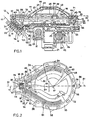
- the container (see Figure 2) comprises a rear portion 52 of substantially circular shape and a front wedge-shaped portion 53 which tapers inwardly towards a terminal portion 54 (see Figure 1) which is inclined downwardly at 45° and on to which the structure 17 is fixed.
- the shape of the tapering portion 53 is such as to permit the printed line to be seen, with the exception of a small number of characters which are in line with the terminal portion 54.
- the container 14 comprises a body or lower shell 56 of plastics material, for example ABS.
- the body 56 is defined by an edge 57 on which there is disposed a series of substantially cylindrical projections 58 (see Figure 2), of elongate section. Also provided on the edge 57 are two reference recesses 59 and 60.
- a hole 61 Disposed in the central part of the lower shell or body 56 (see Figure 1) is a hole 61 into which a metal pin 62 ia fitted and sealed, the metal pin 62 being clinched or riveted to a plate 63 which is also made of metal (see Figure 2).
- the plate 63 has two wings which extend over a susbtantial part of the bottom of the body or shell 56.
- the plate 63 forms the electrode of the print head 12, which is in electrical contact with the ink 16.
- the container 14 further comprises a cover or upper shell 64 of the same material as the lower shell or body 56, being provided with a flat portion 65 over the wedge-shaped portion 53 (Figure 2) of the container 14.
- the shell 64 is provided with an edge 66 ( Figure 1) which is of the same form as the edge 57 of the shell 56.
- the diaphragm 67 is provided with an edge 68 which is greater in thickness than the remainder of the diaphragm 67 and which is arranged to mate with the two edges 57 and 66.
- the edge 68 of the diaphragm is provided with a series of slots 69 (see also Figure 2) into which engage the projections 58 on the edge 57, and two reference projections 71 and 72 which engage into the recesses 59 and 60 in the edge 57.
- the upper shell 64 is provided with an oblong opening 73 in which can be received a locally thickened portion 74 of the diaphragm 67. Part of the thickness of the portion 75 projects downwardly and normally bears against a projection 75 on the bottom of the lower shell 56, ensuring that under all circumstances the diaphragm 67 does not stick to the bottom of the shell 56, by virtue of a reduction in pressure in the space between the diaphragm 67 and the shell 56.
- the container 14 is assembled by fitting the diaphragm 67 on to the lower shell 56 after the projections 71 and 72 have been inserted into the recesses 59 and 60, in such a way as to engage the projections 58 into the slots 69.
- the upper shell 64 is then positioned in such a way that the edge 66 mates with the edge 68 and the edge 64 is secured to the projections 58 by pressure and ultrasonic welding.
- the space between the lower shell 56 and the diaphragm 67 is thus hermetically sealed. That space is filled with the ink 16 after the welding operation, using a syringe through the opening 73.
- the portion 74 which bears against the projection 75 is perforated by means of the syringe needle.
- Air is first extracted from the container 14 and then the required amount of ink is injected, generally being of the order of 3-4 cm 3 which is sufficient for printing over half a million characters.
- the syringe is connected by way of a three- way switchable valve in order to switch it from being connected to an air suction pump to being connected to a pump for injecting the ink.
- the butyl rubber of the diaphragm 67 has elastic characteristics such that, when the needle of the syringe is withdrawn, the hole which is produced thereby in the portion 74 automatically closes off whereby the container 14 can be refilled a number of times.
- the diaphragm 67 always maintains the ink 16 under atmospheric pressure, thus ensuring that any bubbles which are formed within the container 14 by the printing process do not block the nozzle 18 of the structure 17.
- the portion 54 of the container 14 comprises a wall 76 (see Figure 5) which is parallel to the structure 17, for defining in the shell 56 a first space 77 which is disposed between the structure 17 and the wall 76 and a second space 78 which is disposed between the wall 76, the diaphragm 67 and the shell 56.
- the thickness of the space 77 is of the same order of magnitude as the total thickness of the structure 17 and is in communication with the space 78 by way of a section 79 of the wall 76.
- the wall is held in a position of being secured to the shell 56 by way of two plates 80 (see Figure 2) parallel to the central plane 81 of the container 14, which passes through the axis of the nozzle 18, and laterally equally spaced therefrom.
- Two chutes or slipway portions 83 are formed in the floor of the space 78 and are symmetrical with respect to the plane 81 and of a shape that follows the adjacent portion of the edge 57 of the shell 56.
- each chute 83 and the edge 57 Disposed between each chute 83 and the edge 57 are three ribs 84 which are similar in shape to the chute 83 but which extend towards the portion 54 and which form in the shell 56 a series of channels or grooves which are symmetrical with respect to the plane 81.
- the shell 56 comprises a transverse plate 86 which rises from an inclined portion 88 of the bottom of the shell 56 and which extends laterally so as to leave two passages 89 for the ink at the sides.
- the assembly of the chutes 83, the ribs 84 and the plates 80, 82 and 86 services to promote transportation of the ink 16 towards the space 77 until the ink has been totally used up.
- the print head moves transversely with an alternating movement in use, and when the level of the ink 16 drops below the level of the ribs 84 and the chutes 83, at each reversal in the movement of the carriage the ink 16 is displaced outwardly by inertia, passing over the chute 83 into the passages defined between the ribs 84, where it remains. It is then conveyed into the depression formed by the inclined portion 88 and from there passes through the passages 89 between the plates 80 and 82 into the section 79 and the space 77, whereby the nozzle 18 is supplied with ink down to the last drop.
- the container 14 is mounted removably on the carriage 13.
- the carriage 13 is provided with two substantially symmetrical shoulders 91 (see Figure 3) in which two tapered seat members 92 are disposed for positioning purposes.
- the _carriage 13 is provided with a relatively elastic central projection 93 in which there is disposed a further positioning seat member 94 formed by a rectangular member 95 (see Figure 1) and a rounded edge portion 96.
- a coil spring 97 pulls the projection 93 rearwardly.
- the shell 56 (see Figure 2) is in turn provided with two tapering rear projections 98 which are arranged to engage the seat members 92 and a central tapering front projection 99 (see Figure 1) for engaging the seat 94.
- the shell 56 is also provided with a rearward projection 101 (Fig. 1) disposed at a predetermined spacing from the structure 17 and arranged to bear, due to the resilient force of the sliding leaf spring contact 31 against the paper 11, so as to hold the nozzle 18 at a strictly constant distance from the paper.
- a resilient electrical contact 102 fitted beneath the shell 56 is a resilient electrical contact 102 (see Figure 5) which on the one hand bears against the portion 38 of the counter-electrode 36 and on the other hand against the projection 30 (see Figure 1) of the sliding contact 31.
- the heat 12 is therefore fitted to and removed from the carriage 14 with the greatest of ease, by overcoming the force of the spring 97.
- the above-described printing head may be the subject of various modifications and improvements without departing from the scope of the claims.
- the two plates 32 and 41 of the structure 17 may be stuck together before being fixed to the container 14.
- the carriage 13 may be provided, in line with the seat 23, with felt buffers which are impregnated with lubricating oil to facilitate the sliding motion of the carriage 13 on the bar 22.
Landscapes
- Particle Formation And Scattering Control In Inkjet Printers (AREA)
- Ink Jet (AREA)
Claims (14)
Applications Claiming Priority (2)
| Application Number | Priority Date | Filing Date | Title |
|---|---|---|---|
| IT6835583 | 1983-12-27 | ||
| IT68355/83A IT1160247B (it) | 1983-12-27 | 1983-12-27 | Testina di stampa seriale a getto d'inchiostro elettricamente conduttivo |
Publications (3)
| Publication Number | Publication Date |
|---|---|
| EP0147186A2 EP0147186A2 (de) | 1985-07-03 |
| EP0147186A3 EP0147186A3 (en) | 1986-10-08 |
| EP0147186B1 true EP0147186B1 (de) | 1989-04-12 |
Family
ID=11309108
Family Applications (1)
| Application Number | Title | Priority Date | Filing Date |
|---|---|---|---|
| EP84308946A Expired EP0147186B1 (de) | 1983-12-27 | 1984-12-20 | Seriendruckkopf nach der stromleitenden Tintenstrahlart |
Country Status (5)
| Country | Link |
|---|---|
| US (1) | US4630077A (de) |
| EP (1) | EP0147186B1 (de) |
| JP (1) | JPS60168658A (de) |
| DE (1) | DE3477647D1 (de) |
| IT (1) | IT1160247B (de) |
Families Citing this family (11)
| Publication number | Priority date | Publication date | Assignee | Title |
|---|---|---|---|---|
| IT1179109B (it) * | 1984-09-10 | 1987-09-16 | Olivetti & Co Spa | Testina di stampa seriale a getto d'inchiostro |
| IT1182682B (it) * | 1985-11-14 | 1987-10-05 | Olivetti & Co Spa | Testina di stampa a getto d'inchiostro elettricamente conduttivo e relativo dispositivo di stampa |
| JPS62234936A (ja) * | 1986-04-07 | 1987-10-15 | Seiko Epson Corp | 目詰り防止装置 |
| US4872026A (en) * | 1987-03-11 | 1989-10-03 | Hewlett-Packard Company | Ink-jet printer with printhead carriage alignment mechanism |
| USRE37671E1 (en) | 1987-10-23 | 2002-04-30 | Hewlett-Packard Company | Printhead-carriage alignment and electrical interconnect lock-in mechanism |
| US5065169A (en) * | 1988-03-21 | 1991-11-12 | Hewlett-Packard Company | Device to assure paper flatness and pen-to-paper spacing during printing |
| US6183076B1 (en) * | 1992-04-02 | 2001-02-06 | Hewlett-Packard Company | Printer having multi-chamber print cartridges and off-carriage regulator |
| DE4235029C2 (de) * | 1992-10-19 | 1994-07-14 | Pms Gmbh Prod & Recycling | Deckel für einen Druckkopf eines Tintenstrahldruckers |
| US5901425A (en) | 1996-08-27 | 1999-05-11 | Topaz Technologies Inc. | Inkjet print head apparatus |
| US5988802A (en) * | 1996-08-30 | 1999-11-23 | Hewlett-Packard Company | Off-axis ink supply with pressurized ink tube for preventing air ingestion |
| JP4193435B2 (ja) * | 2002-07-23 | 2008-12-10 | ブラザー工業株式会社 | インクカートリッジ、および、そのインク充填方法 |
Family Cites Families (9)
| Publication number | Priority date | Publication date | Assignee | Title |
|---|---|---|---|---|
| IT1129356B (it) * | 1980-10-31 | 1986-06-04 | Olivetti Ing C Spa | Dispositivo di stampa a getto selettivo di inchiostro |
| DE2704735C2 (de) * | 1977-02-04 | 1982-08-05 | Siemens AG, 1000 Berlin und 8000 München | Auslaufsicherer Tintenvorratsbehälter |
| US4131899A (en) * | 1977-02-22 | 1978-12-26 | Burroughs Corporation | Droplet generator for an ink jet printer |
| US4162501A (en) * | 1977-08-08 | 1979-07-24 | Silonics, Inc. | Ink supply system for an ink jet printer |
| JPS5667269A (en) * | 1979-11-06 | 1981-06-06 | Seiko Epson Corp | Ink tank |
| DE3034067C2 (de) * | 1980-09-10 | 1987-03-19 | Siemens AG, 1000 Berlin und 8000 München | Vorrichtung zur Überwachung des Vorrates an Schreibflüssigkeit in Tintenschreibeinrichtungen |
| US4329698A (en) * | 1980-12-19 | 1982-05-11 | International Business Machines Corporation | Disposable cartridge for ink drop printer |
| IT1145242B (it) * | 1981-12-23 | 1986-11-05 | Olivetti & Co Spa | Testina di stampa a getto d inchiostro e relativa stampante seriale |
| IT1145241B (it) * | 1981-12-23 | 1986-11-05 | Olivetti & Co Spa | Testina di stampa seriale a getto d imchiostro |
-
1983
- 1983-12-27 IT IT68355/83A patent/IT1160247B/it active
-
1984
- 1984-12-20 DE DE8484308946T patent/DE3477647D1/de not_active Expired
- 1984-12-20 EP EP84308946A patent/EP0147186B1/de not_active Expired
- 1984-12-26 US US06/686,484 patent/US4630077A/en not_active Expired - Fee Related
- 1984-12-27 JP JP59281860A patent/JPS60168658A/ja active Pending
Also Published As
| Publication number | Publication date |
|---|---|
| US4630077A (en) | 1986-12-16 |
| JPS60168658A (ja) | 1985-09-02 |
| IT8368355A0 (it) | 1983-12-27 |
| EP0147186A3 (en) | 1986-10-08 |
| DE3477647D1 (en) | 1989-05-18 |
| IT1160247B (it) | 1987-03-04 |
| EP0147186A2 (de) | 1985-07-03 |
Similar Documents
| Publication | Publication Date | Title |
|---|---|---|
| US4703332A (en) | Ink jet print head and printer | |
| EP0192428B1 (de) | Thermischer Tintenstrahldrucker mit durch Blasenkollaps verursachten Tröpfchenausstoss | |
| KR910007325B1 (ko) | 잉크 제트 프린터 작동용 오프 보오드 잉크 공급 시스템 및 방법 | |
| EP0082719A2 (de) | Druckkopf für einen Serientintenstrahldrucker | |
| EP0184376B1 (de) | Tintenkartusche für einen Tintenstrahldrucker | |
| US5663754A (en) | Method and apparatus for refilling ink jet cartridges | |
| EP0408241B1 (de) | Thermischer Tintenstrahl-Druckkopf | |
| US4503442A (en) | Ink jet printing head and serial printer | |
| EP0139508B1 (de) | Punktdruckkopf mit Nadelmatrix | |
| US4630077A (en) | Serial printhead ink supply | |
| US4628334A (en) | Ink jet print head cartridge assembly | |
| BRPI0515838B1 (pt) | Reservatório para reter um fluido, selo e conjunto de caneta-tinteiro | |
| EP0174817B1 (de) | Anordnung zum Serienfarbstrahldrucken | |
| EP0895863B1 (de) | Tintenstrahldruckkopf | |
| JPH023321A (ja) | インクカートリッジ | |
| JP2023039337A (ja) | インクタンク、液体収容体、液体吐出装置 | |
| JP3121328B2 (ja) | インクタンクユニット | |
| EP0614762A1 (de) | Punktmatrixdruckkopf | |
| JP2936697B2 (ja) | インクタンク | |
| JP3437336B2 (ja) | 印字装置 | |
| JP2006142816A (ja) | 液体吐出ヘッドおよび液体吐出装置 | |
| JP2706979B2 (ja) | インクジエットヘッド | |
| CA1200144A (en) | Serial ink jet printing head | |
| JPH03286876A (ja) | インクジェット記録装置用インクカートリッジ | |
| JPH08118634A (ja) | インクジェットヘッド |
Legal Events
| Date | Code | Title | Description |
|---|---|---|---|
| PUAI | Public reference made under article 153(3) epc to a published international application that has entered the european phase |
Free format text: ORIGINAL CODE: 0009012 |
|
| AK | Designated contracting states |
Designated state(s): DE FR GB |
|
| PUAL | Search report despatched |
Free format text: ORIGINAL CODE: 0009013 |
|
| AK | Designated contracting states |
Kind code of ref document: A3 Designated state(s): DE FR GB |
|
| 17P | Request for examination filed |
Effective date: 19870320 |
|
| 17Q | First examination report despatched |
Effective date: 19880613 |
|
| GRAA | (expected) grant |
Free format text: ORIGINAL CODE: 0009210 |
|
| AK | Designated contracting states |
Kind code of ref document: B1 Designated state(s): DE FR GB |
|
| REF | Corresponds to: |
Ref document number: 3477647 Country of ref document: DE Date of ref document: 19890518 |
|
| ET | Fr: translation filed | ||
| PLBE | No opposition filed within time limit |
Free format text: ORIGINAL CODE: 0009261 |
|
| STAA | Information on the status of an ep patent application or granted ep patent |
Free format text: STATUS: NO OPPOSITION FILED WITHIN TIME LIMIT |
|
| 26N | No opposition filed | ||
| PGFP | Annual fee paid to national office [announced via postgrant information from national office to epo] |
Ref country code: GB Payment date: 19921208 Year of fee payment: 9 |
|
| PGFP | Annual fee paid to national office [announced via postgrant information from national office to epo] |
Ref country code: FR Payment date: 19921209 Year of fee payment: 9 |
|
| PGFP | Annual fee paid to national office [announced via postgrant information from national office to epo] |
Ref country code: DE Payment date: 19930115 Year of fee payment: 9 |
|
| PG25 | Lapsed in a contracting state [announced via postgrant information from national office to epo] |
Ref country code: GB Effective date: 19931220 |
|
| GBPC | Gb: european patent ceased through non-payment of renewal fee |
Effective date: 19931220 |
|
| PG25 | Lapsed in a contracting state [announced via postgrant information from national office to epo] |
Ref country code: FR Effective date: 19940831 |
|
| PG25 | Lapsed in a contracting state [announced via postgrant information from national office to epo] |
Ref country code: DE Effective date: 19940901 |
|
| REG | Reference to a national code |
Ref country code: FR Ref legal event code: ST |