EP0146468A2 - Ballast-Betonbodenplatte für Offshore-Plattform - Google Patents
Ballast-Betonbodenplatte für Offshore-Plattform Download PDFInfo
- Publication number
- EP0146468A2 EP0146468A2 EP84402550A EP84402550A EP0146468A2 EP 0146468 A2 EP0146468 A2 EP 0146468A2 EP 84402550 A EP84402550 A EP 84402550A EP 84402550 A EP84402550 A EP 84402550A EP 0146468 A2 EP0146468 A2 EP 0146468A2
- Authority
- EP
- European Patent Office
- Prior art keywords
- trellis
- bars
- base
- nodes
- base according
- Prior art date
- Legal status (The legal status is an assumption and is not a legal conclusion. Google has not performed a legal analysis and makes no representation as to the accuracy of the status listed.)
- Granted
Links
Images


Classifications
-
- E—FIXED CONSTRUCTIONS
- E02—HYDRAULIC ENGINEERING; FOUNDATIONS; SOIL SHIFTING
- E02B—HYDRAULIC ENGINEERING
- E02B17/00—Artificial islands mounted on piles or like supports, e.g. platforms on raisable legs or offshore constructions; Construction methods therefor
-
- E—FIXED CONSTRUCTIONS
- E02—HYDRAULIC ENGINEERING; FOUNDATIONS; SOIL SHIFTING
- E02B—HYDRAULIC ENGINEERING
- E02B17/00—Artificial islands mounted on piles or like supports, e.g. platforms on raisable legs or offshore constructions; Construction methods therefor
- E02B17/0004—Nodal points
-
- E—FIXED CONSTRUCTIONS
- E02—HYDRAULIC ENGINEERING; FOUNDATIONS; SOIL SHIFTING
- E02B—HYDRAULIC ENGINEERING
- E02B17/00—Artificial islands mounted on piles or like supports, e.g. platforms on raisable legs or offshore constructions; Construction methods therefor
- E02B17/02—Artificial islands mounted on piles or like supports, e.g. platforms on raisable legs or offshore constructions; Construction methods therefor placed by lowering the supporting construction to the bottom, e.g. with subsequent fixing thereto
- E02B17/025—Reinforced concrete structures
-
- E—FIXED CONSTRUCTIONS
- E04—BUILDING
- E04B—GENERAL BUILDING CONSTRUCTIONS; WALLS, e.g. PARTITIONS; ROOFS; FLOORS; CEILINGS; INSULATION OR OTHER PROTECTION OF BUILDINGS
- E04B1/00—Constructions in general; Structures which are not restricted either to walls, e.g. partitions, or floors or ceilings or roofs
- E04B1/18—Structures comprising elongated load-supporting parts, e.g. columns, girders, skeletons
- E04B1/19—Three-dimensional framework structures
- E04B1/1903—Connecting nodes specially adapted therefor
- E04B1/1906—Connecting nodes specially adapted therefor with central spherical, semispherical or polyhedral connecting element
-
- E—FIXED CONSTRUCTIONS
- E04—BUILDING
- E04B—GENERAL BUILDING CONSTRUCTIONS; WALLS, e.g. PARTITIONS; ROOFS; FLOORS; CEILINGS; INSULATION OR OTHER PROTECTION OF BUILDINGS
- E04B1/00—Constructions in general; Structures which are not restricted either to walls, e.g. partitions, or floors or ceilings or roofs
- E04B1/18—Structures comprising elongated load-supporting parts, e.g. columns, girders, skeletons
- E04B1/19—Three-dimensional framework structures
- E04B2001/1924—Struts specially adapted therefor
- E04B2001/1927—Struts specially adapted therefor of essentially circular cross section
-
- E—FIXED CONSTRUCTIONS
- E04—BUILDING
- E04B—GENERAL BUILDING CONSTRUCTIONS; WALLS, e.g. PARTITIONS; ROOFS; FLOORS; CEILINGS; INSULATION OR OTHER PROTECTION OF BUILDINGS
- E04B1/00—Constructions in general; Structures which are not restricted either to walls, e.g. partitions, or floors or ceilings or roofs
- E04B1/18—Structures comprising elongated load-supporting parts, e.g. columns, girders, skeletons
- E04B1/19—Three-dimensional framework structures
- E04B2001/1924—Struts specially adapted therefor
- E04B2001/1933—Struts specially adapted therefor of polygonal, e.g. square, cross section
-
- E—FIXED CONSTRUCTIONS
- E04—BUILDING
- E04B—GENERAL BUILDING CONSTRUCTIONS; WALLS, e.g. PARTITIONS; ROOFS; FLOORS; CEILINGS; INSULATION OR OTHER PROTECTION OF BUILDINGS
- E04B1/00—Constructions in general; Structures which are not restricted either to walls, e.g. partitions, or floors or ceilings or roofs
- E04B1/18—Structures comprising elongated load-supporting parts, e.g. columns, girders, skeletons
- E04B1/19—Three-dimensional framework structures
- E04B2001/1981—Three-dimensional framework structures characterised by the grid type of the outer planes of the framework
- E04B2001/1984—Three-dimensional framework structures characterised by the grid type of the outer planes of the framework rectangular, e.g. square, grid
-
- E—FIXED CONSTRUCTIONS
- E04—BUILDING
- E04B—GENERAL BUILDING CONSTRUCTIONS; WALLS, e.g. PARTITIONS; ROOFS; FLOORS; CEILINGS; INSULATION OR OTHER PROTECTION OF BUILDINGS
- E04B1/00—Constructions in general; Structures which are not restricted either to walls, e.g. partitions, or floors or ceilings or roofs
- E04B1/18—Structures comprising elongated load-supporting parts, e.g. columns, girders, skeletons
- E04B1/19—Three-dimensional framework structures
- E04B2001/1981—Three-dimensional framework structures characterised by the grid type of the outer planes of the framework
- E04B2001/1987—Three-dimensional framework structures characterised by the grid type of the outer planes of the framework triangular grid
-
- E—FIXED CONSTRUCTIONS
- E04—BUILDING
- E04B—GENERAL BUILDING CONSTRUCTIONS; WALLS, e.g. PARTITIONS; ROOFS; FLOORS; CEILINGS; INSULATION OR OTHER PROTECTION OF BUILDINGS
- E04B1/00—Constructions in general; Structures which are not restricted either to walls, e.g. partitions, or floors or ceilings or roofs
- E04B1/18—Structures comprising elongated load-supporting parts, e.g. columns, girders, skeletons
- E04B1/19—Three-dimensional framework structures
- E04B2001/199—Details of roofs, floors or walls supported by the framework
-
- E—FIXED CONSTRUCTIONS
- E04—BUILDING
- E04B—GENERAL BUILDING CONSTRUCTIONS; WALLS, e.g. PARTITIONS; ROOFS; FLOORS; CEILINGS; INSULATION OR OTHER PROTECTION OF BUILDINGS
- E04B1/00—Constructions in general; Structures which are not restricted either to walls, e.g. partitions, or floors or ceilings or roofs
- E04B1/18—Structures comprising elongated load-supporting parts, e.g. columns, girders, skeletons
- E04B1/19—Three-dimensional framework structures
- E04B2001/1993—Details of framework supporting structure, e.g. posts or walls
Definitions
- the present invention relates to concrete constructions.
- An object of the invention is to provide a concrete construction capable of constituting a ballastable base for an offshore platform.
- Another object of the invention is to provide a concrete construction capable of constituting a three-dimensional supporting trellis.
- Ballastable concrete bases of offshore platforms consist of solid concrete walls. These bases can be suitable for platforms intended for cold seas because they have sufficient strength to withstand the pressure of the ice which can be very high but it has the drawback of having a very high weight. We tried to reduce this weight by using light concrete but this solution is very expensive and does not give any satisfaction.
- the present invention aims to provide a base which can be made of normal concrete, which offers maximum resistance and which, however, is of reasonable weight.
- the base of the present invention essentially consists of a volume formed by a rigid three-dimensional lattice of concrete bars assembled into concrete nodes, certain nodes being connected to each other by clamping cables which pass outside the bars and which optionally pass through intermediate nodes, these cables performing a three-dimensional prestressing of the entire trellis, the base comprising means for making the sides and the bottom of the trellis waterproof.
- the trellis consists of an assembly of prefabricated blocks by molding, each block comprising a core and a plurality of arms which radiate from the core, each arm having at least one longitudinal housing opening out at the end. free of the arm, the arms being assembled two by two in alignment to constitute the lattice bars, the housings of the assembled arms being aligned and containing a common metal frame, the junction zone of the assembled arms being surrounded by a sealing sleeve, said housings being filled with hardened mortar, and said trellis being clamped by prestressing cables which pass outside the bars of the trellis and which are fixed to nodes of the trellis.
- the platform base shown in Figures 1 and 2 is a hexagonal base whose edge is 72 m.
- This base consists of a trellis which is provided with a sealed front and which has a sealed bottom.
- the trellis consists of concrete bars assembled in nodes and the lateral facade of this trellis constitutes inclined planes on which the facade of the base rests.
- the trellis it is convenient to constitute the trellis by an assembly of regular tetrahedra, the nodes constituting the vertices of the tetrahedra and the bars being arranged according to the edges of the tetrahedra.
- the lattice bars form squares in planes inclined at 50-60 °, form equilateral triangles in planes inclined at 65-75 ° and form equilateral triangles in horizontal planes.
- the sides of the trellis alternately comprise planes where the bars of the trellis form equilateral or isosceles triangles and planes where the bars of the trellis form squares or rectangles.
- the section plane of Figure 1 is a vertical plane and the view represents one half of the section plane.
- Figure 2 there are shown horizontal section planes.
- Figure 2 is divided into six portions which each represent a fraction of horizontal section at a certain level.
- the marks 1 , 2, 3, 4, 5, 6 represent cutting planes at the levels O m, 5 m, 10 m, 15 m, 20 m, 25 m approximately.
- the lower plane of the trellis which is made up of a mosaic of equilateral triangles A, B, C whose sides are formed by bars of the trellis and whose vertices are formed by lattice nodes.
- section plane in FIG. 1 is a plane along the line A-A in FIG. 2.
- the trellis is made by any suitable technique and the following technique is preferably used.
- blocks comprising a central core and arms which radiate from the core are molded by injection molding in a closed mold.
- the core is intended to constitute a knot of the trellis and each arm is intended to constitute a part of a bar of the trellis.
- part of the lower level of the trellis then, in gradient, part of the level placed above, and so on to the upper level, the machines necessary for the installation of the blocks being able to roll on the ground from where the we do the editing.
- the invention makes it possible to carry out a large part of the work outside the dry dock, since only the assembly of the blocks is carried out in dry dock.
- any suitable means can be used and, preferably, the two arms are provided, at prefabrication, with two housings which will open one opposite the other when the arms are placed end to end, these two housings being each provided with a passage making it possible to introduce mortar into the housings and, simultaneously, to empty the air from the housings.
- a common frame is placed in the two housings, the junction of the two arms is surrounded by a sleeve and mortar is introduced into the two housings until it sets.
- the sleeve provides lateral sealing.
- a sleeve made of heat-shrinkable material is used.
- the mortar which fills the housings can constitute between the opposite faces of the two arms a more or less thick joint acting as a jack between the two arms.
- This more or less thick joint J makes it possible to position the two prefabricated blocks on demand one with respect to the other and it is the same step by step for all the blocks.
- Figure 4 is a diagram explaining the technique of assembling two arms, as described above.
- the arms are marked 14.14 ', the corresponding cores 15.15', the corresponding housings 16.16 ', the passages of the housings 17.17', the sleeve 18 and the armature 19.
- the arms are bars whose cross section is part of a circle with a diameter of 20 to 100 cm and. which are 2 to 10 meters long. Preference is given to bars of circular section whose diameter is in the range 30-80 cm and preferably used for the assembly of the arms, a mortar having a high compressive strength, of the order of 600 to 1,000 bars.
- each arm constitutes a half bar.
- the entire trellis is clamped by cables which carry out a three-dimensional prestress. These cables are fixed at their ends to nodes of the trellis.
- a cable alternately and repeatedly meets a trellis bar which it crosses substantially in the middle and orthogonally, and a node of the trellis which it crosses.
- Figure 3 of the accompanying drawing shows, by way of example only, a block consisting of a core 1 from which radiate 12 arms (2-13) which each constitute a half-bar of the trellis.
- the blocks located on the end planes of the trellis that is to say the planes which constitute the bottom, the sides and the top of the trellis, have a lower number of arms, as it is understood.
- the bottom and sides of the base are sealed.
- the watertight bottom is preferably made up of a mosaic of pyramids, which allows it to sink into the underlying soil on demand at the final location of the platform.
- Figure 5 is a perspective showing an element of the pyramid in one of the lattice tetrahedra.
- the pyramid and the tetrahedron have a common base DEF but the vertex G of the tetrahedron is above the vertex H of the pyramid.
- the two halves are then assembled by any suitable method and, for example, by a technique analogous to that which allows the assembly of two arms to form a bar.
- the pyramids at the bottom of the base are mounted at the same time as the nodes of the lower level of the trellis are mounted.
- the facade of the base is preferably an embossed concrete facade.
- This facade (FIG. 6), it is convenient to prefabricate concrete dihedra made up of two planes P1 P2 and to join these planes to the bars of the surface of the lattice against which the facade is applied. It is therefore advantageous that in this surface the bars of the trellis constitute rectangles which extend in the height of the surface of the trellis and the walls P1, P2 are tightly joined with the bars b located along the long sides of the rectangle. and so step by step.
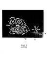
- FIGS 7 to 10 show alternative embodiments according to the invention.
- the molded block consists of a spherical central core 15 from which radiate cylindrical arms 14. A part of a lattice made up of these blocks is shown to the right of the block and we see on this lattice sleeves 18 which are mounted on the lattice bars.
- part of a trellis is shown.
- the bars of the trellis which are in the planes underlying the facade are arranged along the sides of squares Q and along the sides of squares Q and along the sides of triangles T which, possibly, draw trapezoids.
- part of a trellis is also shown.
- the bars of the trellis which found in the plans underlying the facade are arranged along the sides of squares Q and along the sides of triangles T which possibly draw trapezoids.
- FIG. 9 part of the side facade is also shown.
- this side facade is made up of facade portions. In fact, each facade portion is integral with one of the lattice tetrahedra and the various facade portions are joined together gradually by mortar or added concrete.
- FIG. 10 is a simplified view schematically showing two prestressing cables 20,21.
- the prestressing cable 20 is straight and its ends are fixed to two nodes 22, 23 of the trellis.
- the cable crosses several bars of the trellis such as bars 24,25 but remains outside the bars.
- the prestressing cable 21 is also attached at its two ends to nodes 26,27 of the trellis, but this cable is not straight and it is deflected by nodes of the trellis such as nodes 28,29.
- the node 28 is provided with a groove 30 and the node 29 is provided with an internal passage 31 for deflecting the cable 21. Only part of the arms of these nodes is shown in the drawing.
- the invention is not limited to a specific geometrical arrangement of the bars but, preferably, the bars of the lateral faces of the trellis are arranged along the sides of equilateral or isosceles triangles and / or along the sides of rectangles or squares.
- the side faces are planes inclined relative to the vertical but, in other embodiments, they are vertical.
- the sides and bottom of the trellis are sealed by any suitable means.
- the seal is obtained by a plurality of concrete walls which are fixed in a sealed manner or which are in one piece with the bars of the lattice which are located in the lateral faces and in the bottom face of the lattice.
- the walls which seal one side of the trellis are arranged in a pleated arrangement, which reduces the effects of the temperature difference between the part of this side which is in the water and the part of this side which is in the water. - above the water.
- Such a temperature difference, which in cold seas can be 50 ° C or more, could cause destructive stresses if the side walls were flat.
- the term "pleated” should be understood as a global term which includes all configurations and all dimensions of pleats.
- the invention is particularly applicable to the production of structures at sea, including to form reservoirs.
Landscapes
- Engineering & Computer Science (AREA)
- General Engineering & Computer Science (AREA)
- Civil Engineering (AREA)
- Structural Engineering (AREA)
- Mechanical Engineering (AREA)
- Architecture (AREA)
- Physics & Mathematics (AREA)
- Electromagnetism (AREA)
- Reinforcement Elements For Buildings (AREA)
- Revetment (AREA)
- Foundations (AREA)
- Epoxy Compounds (AREA)
- Building Environments (AREA)
Applications Claiming Priority (2)
| Application Number | Priority Date | Filing Date | Title |
|---|---|---|---|
| FR8320091 | 1983-12-14 | ||
| FR8320091A FR2556756B1 (fr) | 1983-12-14 | 1983-12-14 | Embase en beton de type ballastable pour plate-forme en mer |
Publications (3)
| Publication Number | Publication Date |
|---|---|
| EP0146468A2 true EP0146468A2 (de) | 1985-06-26 |
| EP0146468A3 EP0146468A3 (en) | 1985-08-21 |
| EP0146468B1 EP0146468B1 (de) | 1987-03-25 |
Family
ID=9295202
Family Applications (1)
| Application Number | Title | Priority Date | Filing Date |
|---|---|---|---|
| EP84402550A Expired EP0146468B1 (de) | 1983-12-14 | 1984-12-11 | Ballast-Betonbodenplatte für Offshore-Plattform |
Country Status (9)
| Country | Link |
|---|---|
| US (1) | US4653959A (de) |
| EP (1) | EP0146468B1 (de) |
| JP (1) | JPS6124716A (de) |
| KR (1) | KR890004174B1 (de) |
| CA (1) | CA1218242A (de) |
| DE (1) | DE3462811D1 (de) |
| FR (1) | FR2556756B1 (de) |
| MX (1) | MX162914B (de) |
| OA (1) | OA07895A (de) |
Cited By (1)
| Publication number | Priority date | Publication date | Assignee | Title |
|---|---|---|---|---|
| FR2659368A1 (fr) * | 1990-03-12 | 1991-09-13 | Bouygues Offshore | Structure tubulaire en beton, notamment pour structure en mer. |
Families Citing this family (3)
| Publication number | Priority date | Publication date | Assignee | Title |
|---|---|---|---|---|
| US12163345B2 (en) | 2020-04-14 | 2024-12-10 | Voidform Products, Llc | Modular void form structure |
| CN113931227B (zh) * | 2021-09-17 | 2025-01-07 | 中铁工程机械研究设计院有限公司 | 一种地铁装配式车站顶层组件拼装机及拼装方法 |
| US12000104B1 (en) * | 2022-03-10 | 2024-06-04 | Theo Robert Seeley | Green gravity retaining wall |
Family Cites Families (23)
| Publication number | Priority date | Publication date | Assignee | Title |
|---|---|---|---|---|
| US954283A (en) * | 1908-01-17 | 1910-04-05 | Frederick W Hawkes | Revetment. |
| US1425114A (en) * | 1922-02-28 | 1922-08-08 | Luard Edward Sydney | Concrete construction |
| FR901127A (fr) * | 1943-09-06 | 1945-07-18 | Procédé de construction | |
| US2653451A (en) * | 1948-07-02 | 1953-09-29 | Brown And Root Inc | Pedestal |
| US2970388A (en) * | 1956-05-07 | 1961-02-07 | Edward H Yonkers | Education device |
| US3083793A (en) * | 1959-09-21 | 1963-04-02 | Brout Robert Benedict | Membrane sustained roof structure |
| US3284113A (en) * | 1964-03-04 | 1966-11-08 | William M Howell | Picture frame structure |
| US3343324A (en) * | 1964-03-24 | 1967-09-26 | Gordon William | Underwater structural unit |
| US3382625A (en) * | 1965-05-19 | 1968-05-14 | Robert S. Kuss | Prestressed enclosure |
| GB1125840A (en) * | 1966-09-06 | 1968-09-05 | Nat Res Dev | Skeletal molecular models |
| US3466823A (en) * | 1967-11-27 | 1969-09-16 | Seamus Dowling | Space form skeleton structures made of prefabricated tri-axial interlocking building elements having non-rigid force distributing connectors |
| US3722153A (en) * | 1970-05-04 | 1973-03-27 | Zomeworks Corp | Structural system |
| JPS523487B2 (de) * | 1973-01-11 | 1977-01-28 | ||
| FR2287378A1 (fr) * | 1974-10-07 | 1976-05-07 | Seven Seas Engin Ltd | Perfectionnements aux structures cellulaires en beton |
| FR2299462A1 (fr) * | 1975-01-31 | 1976-08-27 | Ono Taisaburo | Element de construction d'echafaudage sous l'eau |
| US4059931A (en) * | 1976-01-29 | 1977-11-29 | Mongan William T | Building framing system for post-tensioned modular building structures |
| US4074497A (en) * | 1976-06-01 | 1978-02-21 | Taisaburo Ono | Underwater trusses for breakwater structure |
| JPS5434244A (en) * | 1977-08-22 | 1979-03-13 | Minolta Camera Co Ltd | Developing sleeve |
| US4161088A (en) * | 1977-11-11 | 1979-07-17 | Gugliotta Paul F | Pipe-and-ball truss array |
| US4189252A (en) * | 1978-09-01 | 1980-02-19 | Cygnus X-5 Company Inc. | Undersea platform construction system |
| JPS5595714A (en) * | 1979-01-12 | 1980-07-21 | Takechi Koumushiyo:Kk | Pile unit and pile with knot |
| US4426173A (en) * | 1981-08-27 | 1984-01-17 | Exxon Production Research Co. | Remote alignment method and apparatus |
| US4504172A (en) * | 1983-07-11 | 1985-03-12 | Mobil Oil Corporation | Caisson shield for arctic offshore production platform |
-
1983
- 1983-12-14 FR FR8320091A patent/FR2556756B1/fr not_active Expired
-
1984
- 1984-12-10 MX MX203666A patent/MX162914B/es unknown
- 1984-12-11 EP EP84402550A patent/EP0146468B1/de not_active Expired
- 1984-12-11 DE DE8484402550T patent/DE3462811D1/de not_active Expired
- 1984-12-11 US US06/680,641 patent/US4653959A/en not_active Expired - Lifetime
- 1984-12-13 CA CA000470001A patent/CA1218242A/en not_active Expired
- 1984-12-14 KR KR1019840007938A patent/KR890004174B1/ko not_active Expired
- 1984-12-14 JP JP26435384A patent/JPS6124716A/ja active Granted
- 1984-12-14 OA OA58472A patent/OA07895A/xx unknown
Cited By (2)
| Publication number | Priority date | Publication date | Assignee | Title |
|---|---|---|---|---|
| FR2659368A1 (fr) * | 1990-03-12 | 1991-09-13 | Bouygues Offshore | Structure tubulaire en beton, notamment pour structure en mer. |
| EP0447310A1 (de) * | 1990-03-12 | 1991-09-18 | Bouygues Offshore | Rohrförmige Struktur aus Beton, insbesondere für Bauwerke im Meer |
Also Published As
| Publication number | Publication date |
|---|---|
| JPH0317005B2 (de) | 1991-03-07 |
| EP0146468A3 (en) | 1985-08-21 |
| FR2556756A1 (fr) | 1985-06-21 |
| EP0146468B1 (de) | 1987-03-25 |
| JPS6124716A (ja) | 1986-02-03 |
| OA07895A (fr) | 1986-11-20 |
| MX162914B (es) | 1991-07-08 |
| US4653959A (en) | 1987-03-31 |
| KR890004174B1 (ko) | 1989-10-23 |
| KR850004286A (ko) | 1985-07-11 |
| DE3462811D1 (en) | 1987-04-30 |
| CA1218242A (en) | 1987-02-24 |
| FR2556756B1 (fr) | 1987-08-28 |
Similar Documents
| Publication | Publication Date | Title |
|---|---|---|
| EP0146469B1 (de) | Raumfachwerk aus Beton und Verfahren zur Herstellung des genannten Fachwerkes | |
| EP0180667B1 (de) | Vorgefertigte Baueinheiten und Gebrauch im Hochbau | |
| FR2554479A1 (fr) | Systeme de blocs de construction pour eriger des edifices | |
| CA2225508A1 (fr) | Remblai allege | |
| EP0146468B1 (de) | Ballast-Betonbodenplatte für Offshore-Plattform | |
| FR2642109A1 (fr) | Structure creuse allongee et son procede de fabrication | |
| FR2556387A1 (fr) | Element de construction du type en polystyrene expanse, destine a la realisation de mur | |
| FR2817573A1 (fr) | Mur de soubassement pour une construction et procede de realisation d'un tel mur | |
| FR2702784A1 (fr) | Elément de construction d'un ouvrage de soutènement et mur de soutènement. | |
| EP2148019A2 (de) | Blockbaustein für Mauern | |
| FR2652845A1 (fr) | Ensemble de construction. | |
| BE1008399A6 (fr) | Bloc de construction evide interieurement, destine a recevoir un coulis durcissable. | |
| EP1274902B1 (de) | Modulare künstliche riffanlage | |
| FR2686107A1 (fr) | Procede pour la fabrication de modules de construction precontraints notamment en bois et modules de construction ainsi obtenus notamment pour structure architecturales. | |
| EP3628791B1 (de) | Fertigbauelement vom typ mauer mit integrierter schalung | |
| BE1027286B1 (fr) | Elément constitutif d'une construction | |
| FR2725742A1 (fr) | Element de mur vegetal et mur vegetal constitue d'une pluralite de tels elements | |
| EP4124692B1 (de) | Versetzbare mauer mit betonskelett | |
| FR2764318A1 (fr) | Structure de protection et de renfort d'ouvrages | |
| WO1994028263A2 (fr) | Procede de fabrication d'elements de construction destines a l'erection de piliers et elements obtenus selon ce procede | |
| FR2772813A1 (fr) | Etancheite d'une structure de piscine realisee par un assemblage de panneaux en polyester | |
| FR2912440A1 (fr) | Panneau prefabrique destine a former une paroi isolante d'un batiment,et procede de fabrication de ce panneau | |
| WO1990011417A1 (fr) | Structure notamment en bois et procede de realisation | |
| FR2840929A1 (fr) | Element prefabrique pour chambre de tirage et chambre de tirage comprenant un tel element | |
| FR2593214A1 (fr) | Elements modulaires prefabriques pour construction de piscines et procede de fabrication (coffrages perdus) |
Legal Events
| Date | Code | Title | Description |
|---|---|---|---|
| PUAI | Public reference made under article 153(3) epc to a published international application that has entered the european phase |
Free format text: ORIGINAL CODE: 0009012 |
|
| PUAL | Search report despatched |
Free format text: ORIGINAL CODE: 0009013 |
|
| AK | Designated contracting states |
Designated state(s): BE DE FR GB IT NL SE |
|
| AK | Designated contracting states |
Designated state(s): BE DE FR GB IT NL SE |
|
| 17P | Request for examination filed |
Effective date: 19850715 |
|
| 17Q | First examination report despatched |
Effective date: 19860610 |
|
| GRAA | (expected) grant |
Free format text: ORIGINAL CODE: 0009210 |
|
| ITF | It: translation for a ep patent filed | ||
| AK | Designated contracting states |
Kind code of ref document: B1 Designated state(s): BE DE FR GB IT NL SE |
|
| REF | Corresponds to: |
Ref document number: 3462811 Country of ref document: DE Date of ref document: 19870430 |
|
| PLBE | No opposition filed within time limit |
Free format text: ORIGINAL CODE: 0009261 |
|
| STAA | Information on the status of an ep patent application or granted ep patent |
Free format text: STATUS: NO OPPOSITION FILED WITHIN TIME LIMIT |
|
| 26N | No opposition filed | ||
| ITTA | It: last paid annual fee | ||
| EAL | Se: european patent in force in sweden |
Ref document number: 84402550.2 |
|
| PGFP | Annual fee paid to national office [announced via postgrant information from national office to epo] |
Ref country code: NL Payment date: 19971130 Year of fee payment: 14 |
|
| PGFP | Annual fee paid to national office [announced via postgrant information from national office to epo] |
Ref country code: GB Payment date: 19971205 Year of fee payment: 14 |
|
| PGFP | Annual fee paid to national office [announced via postgrant information from national office to epo] |
Ref country code: SE Payment date: 19971222 Year of fee payment: 14 Ref country code: DE Payment date: 19971222 Year of fee payment: 14 |
|
| PGFP | Annual fee paid to national office [announced via postgrant information from national office to epo] |
Ref country code: BE Payment date: 19980115 Year of fee payment: 14 |
|
| PG25 | Lapsed in a contracting state [announced via postgrant information from national office to epo] |
Ref country code: GB Free format text: LAPSE BECAUSE OF NON-PAYMENT OF DUE FEES Effective date: 19981211 |
|
| PG25 | Lapsed in a contracting state [announced via postgrant information from national office to epo] |
Ref country code: SE Free format text: LAPSE BECAUSE OF NON-PAYMENT OF DUE FEES Effective date: 19981212 |
|
| PG25 | Lapsed in a contracting state [announced via postgrant information from national office to epo] |
Ref country code: BE Free format text: LAPSE BECAUSE OF NON-PAYMENT OF DUE FEES Effective date: 19981231 |
|
| BERE | Be: lapsed |
Owner name: BOUYGUES Effective date: 19981231 |
|
| PG25 | Lapsed in a contracting state [announced via postgrant information from national office to epo] |
Ref country code: NL Free format text: LAPSE BECAUSE OF NON-PAYMENT OF DUE FEES Effective date: 19990701 |
|
| GBPC | Gb: european patent ceased through non-payment of renewal fee |
Effective date: 19981211 |
|
| NLV4 | Nl: lapsed or anulled due to non-payment of the annual fee |
Effective date: 19990701 |
|
| PG25 | Lapsed in a contracting state [announced via postgrant information from national office to epo] |
Ref country code: DE Free format text: LAPSE BECAUSE OF NON-PAYMENT OF DUE FEES Effective date: 19991001 |
|
| PGFP | Annual fee paid to national office [announced via postgrant information from national office to epo] |
Ref country code: FR Payment date: 20001228 Year of fee payment: 17 |
|
| PG25 | Lapsed in a contracting state [announced via postgrant information from national office to epo] |
Ref country code: FR Free format text: LAPSE BECAUSE OF NON-PAYMENT OF DUE FEES Effective date: 20020830 |
|
| REG | Reference to a national code |
Ref country code: FR Ref legal event code: ST |