EP0146166B1 - Schweisskopf für Widerstandsschweissen - Google Patents
Schweisskopf für Widerstandsschweissen Download PDFInfo
- Publication number
- EP0146166B1 EP0146166B1 EP84201698A EP84201698A EP0146166B1 EP 0146166 B1 EP0146166 B1 EP 0146166B1 EP 84201698 A EP84201698 A EP 84201698A EP 84201698 A EP84201698 A EP 84201698A EP 0146166 B1 EP0146166 B1 EP 0146166B1
- Authority
- EP
- European Patent Office
- Prior art keywords
- carrier
- electrode
- welding
- welding head
- prismatic
- Prior art date
- Legal status (The legal status is an assumption and is not a legal conclusion. Google has not performed a legal analysis and makes no representation as to the accuracy of the status listed.)
- Expired
Links
Images

Classifications
-
- B—PERFORMING OPERATIONS; TRANSPORTING
- B23—MACHINE TOOLS; METAL-WORKING NOT OTHERWISE PROVIDED FOR
- B23K—SOLDERING OR UNSOLDERING; WELDING; CLADDING OR PLATING BY SOLDERING OR WELDING; CUTTING BY APPLYING HEAT LOCALLY, e.g. FLAME CUTTING; WORKING BY LASER BEAM
- B23K11/00—Resistance welding; Severing by resistance heating
- B23K11/30—Features relating to electrodes
- B23K11/31—Electrode holders and actuating devices therefor
- B23K11/318—Supporting devices for electrode holders
Definitions
- the invention relates to a welding head for resistance welding, in particular for spot welding.
- Known apparatus of the kind set forth, described for example in U.S. Patent Specification 3,191,000 comprise a frame to which a welding electrode is fastened in a fixed position, whilst a second welding electrode lying substantially opposite the first electrode is movable in the direction to the first electrode. To this end the second electrode is connected with a carrier, which is movable with respect to the frame.
- the first electrode is in a fixed position. This does not mean, however, that this position cannot be changed with respect to the frame, since usually the first electrode is connected with a transverse carrier which is displaceable with respect to the frame.
- the movement of the carrier of the second electrode with respect to the frame is often carried out by foot-control and a lever or else by means of pneumatically or hydraulically actuated plunger.
- the weld is established after the first and the second electrode are brought into contact with the two parts to be connected located between the electrodes.
- the force by which the second electrode is pressed against the work piece should have a given value depending inter alia on the thickness of the material and the conductabil- ity thereof.
- U.S. Patent Specification 3,191,000 provides inter alia a spring structure. The welding current is switched on at the instant at which the pressing force attains said given value.
- the material between the electrodes is first heated so that the metal of the parts to be joined expands. Then fusion occurs in the transition zone.
- the two parts must, of course, remain in contact with one another. It is, therefore, necessary for the movement of one electrode to be very accurately controlled.
- the duration of pressure is too short no satisfactory weld is formed because solidification has not yet taken place.
- the DE-A-2738854 shows a further development of a welding head based on the discovery that sometimes unsatisfactory welds were due to the fact that the movable part and the electrode connected herewith could not sufficiently rapidly follow the expansion and subsequent shrinkage and/or followed the same too late. The cause thereof was ascribed to the excessive mass and hence the excessive inertia of the carrier.
- the invention has for its object to obviate in particular the last mentioned disadvantage.
- a welding head according to the invention for resistance welding shows the constructional features as stated in the preamble of the first claim and is characterized in that the element and the space of the carrier in which it slides have a prismatic cross-section, whereby the element is prevented from turning in the carrier.
- the inertia of the element is preferably designed in the form of a hollow body.
- the element and the carrier are interconnected by a combination of a compression spring and a tensile spring to reduce back-lash.
- the element In order to minimize the inertia of the element it is preferably made from a metal having a specific weight below 4, in particular aluminium, or synthetic resin.
- the carrier may also be made from a light-weight material.
- a light-weight material for example, aluminium or a synthetic resin.
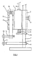
- reference numeral 1 designates a frame to which a block 2 is rigidly secured by means of a screw 3.
- the frame 1 carries a first, lower welding electrode 5.
- a beam 4 is fastened by means of a bolt 6 to the frame 1 and displaceable along the same in a direction of height.
- To the block 2 is fastened a carrier 7 in a manner such that it can slide up and down along the block 2. This movement is limited on two sides by end switches and is produced by means of a pin 8 coupled, for example, with a pneumatically operating cylinder.
- a beam 9 which is rigidly secured to the frame 1 by means of a bolt 10. During the downward movement of the pin 8 a spring 11 located between the carrier 7 and the beam 9 is compressed.
- a cavity 12 of the carrier 7 accommodates an element 13, which can slide up and down in said cavity.
- a hollow transverse beam 14 embedded in a synthetic resin holder (Fig. 2) carrying the second welding electrode 15, which is insulated from the electrode 5.
- a compression spring 16 Between the top side of the element 13 and the bottom of the cavity 12 is arranged a compression spring 16.
- needles or balls 17 are arranged between the carrier 7 and the element 13 for reducing friction between the last-mentioned parts.
- the pin 8 is pressed against the force of the spring 11 to produce a downward movement of the carrier 7.
- This downward movement is transferred by means of the spring 16 to the element 13 and the second welding electrode 15 connected with the latter.
- the spring 16 is slightly compressed. This spring fixes the pressure exerted by the electrodes on the parts to be joined.
- the welding current is switched on as soon as the pressure force attains a given value. It is of essential importance that this force should be maintained for the entire welding cycle which usually does not take more than a few milliseconds.
- the parts to be joined expand and subsequently shrink. It is of essential importance for the electrodes to follow this movement resulting from the thermal effect. If the spring 16 were lacking, the pressure force would strongly increase. The spring 16 however, ensures that the force maintains a substantially constant value despite the expansion and the subsequent shrinkage at the welding area. The same could be believed to be obtainable if the element 13 were rigidly secured to the carrier 7 and a spring were disposed between the pin 8 and the carrier 7. Since the whole welding operation on the parts to be joined is very rapidly performed it is necessary for the upward and downward movement of the element 13 to match the operation within the time fixed.
- the whole carrier which has a fairly heavy weight and hence a fairly high inertia for structural reasons, has to be moved up and down, it would practically not be possible to maintain constant the pressure between the electrodes 5 and 15 and the work piece.
- the element 13 need move up and down and this element has a materially smaller mass than the carrier 7. This enables to maintain the pressure between the electrodes 5 and 15 substantially constant.
- the mass of the element 13 may, moreover, be reduced by making it hollow.
- the friction between the carrier 7 and the element 13 can be considerably reduced by means of rollers or balls 17. A further reduction of the weight of the element 13 can be obtained by selection of the material.
- this element a material having a specific weight below 4, in particular aluminium.
- the selection of the material for the carrier 7 is in the first place determined by structural considerations. However, even then aluminium is preferred. Thus the weight of the whole construction is lower and the rate of movement of the carrier 7 may be chosen to be higher.
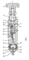
- Fig. 2 parts corresponding with those shown in Fig. 1 are designated by the same reference numerals.
- the compression spring 16 is located between the top side of the element 13 and an angle-section beam 17, which is fastened at 18 by means of a bolt to the movable carrier.
- Reference numeral 19 designates a screw by means of which the bias tension of the spring 16 can be set.
- the element 13 is a hollow prism.
- the angle-section fillet 20 is connected with the carrier 7 by means of bolts 21, which extend through elongate holes in the element 13.
- elongate needle bearings are formed by rollers 22 accommodated in plate- shaped cages 23.
- the inclined sides of the carrier 7 and the angle-section fillet 20 are provided with hard steel strips 24. Similar hard steel strips are provided on the prismatic element 13. These strips are particularly required when the parts 7, 20 and 13 are made from aluminium or synthetic resin. They may be fastened to the various parts by gluing.
- the carrier 7 can slide along the block 2 by means of the device designated by 25.
- This device comprises angle-section steel fillets 26 and elongate bearing blocks 27 bearing on the former.
- Both the element and the carrier may be made from a synthetic resin.
- an advantageous value of the number of welds made per unit time is attained-since the welding head being reduced can be more rapidly moved up and down-and on the other hand, owing to the low weight of the element an advantageous value is obtained for the rate of follow-up of the electrode.
- welding head embodying the invention may also be used for soldering with the aid of "reflow" techniques.
- the prism Since the prism is turned through 45° it can be fastened by means of pins or bolts extending along a diagonal so that division of the bearings is avoided and a compact construction can be made.
Landscapes
- Engineering & Computer Science (AREA)
- Mechanical Engineering (AREA)
- Resistance Welding (AREA)
- Arc Welding In General (AREA)
Claims (8)
Priority Applications (1)
| Application Number | Priority Date | Filing Date | Title |
|---|---|---|---|
| AT84201698T ATE40657T1 (de) | 1983-12-05 | 1984-11-23 | Schweisskopf fuer widerstandsschweissen. |
Applications Claiming Priority (2)
| Application Number | Priority Date | Filing Date | Title |
|---|---|---|---|
| NL8304167 | 1983-12-05 | ||
| NL8304167A NL8304167A (nl) | 1983-12-05 | 1983-12-05 | Laskop voor weerstandslassen. |
Publications (3)
| Publication Number | Publication Date |
|---|---|
| EP0146166A2 EP0146166A2 (de) | 1985-06-26 |
| EP0146166A3 EP0146166A3 (en) | 1985-07-24 |
| EP0146166B1 true EP0146166B1 (de) | 1989-02-08 |
Family
ID=19842824
Family Applications (1)
| Application Number | Title | Priority Date | Filing Date |
|---|---|---|---|
| EP84201698A Expired EP0146166B1 (de) | 1983-12-05 | 1984-11-23 | Schweisskopf für Widerstandsschweissen |
Country Status (6)
| Country | Link |
|---|---|
| US (1) | US4572940A (de) |
| EP (1) | EP0146166B1 (de) |
| JP (1) | JPS60145290A (de) |
| AT (1) | ATE40657T1 (de) |
| DE (1) | DE3476639D1 (de) |
| NL (1) | NL8304167A (de) |
Families Citing this family (14)
| Publication number | Priority date | Publication date | Assignee | Title |
|---|---|---|---|---|
| JPS6296975U (de) * | 1985-12-09 | 1987-06-20 | ||
| JPS6356369A (ja) * | 1986-08-27 | 1988-03-10 | Mitsubishi Electric Corp | 溶接機ヘツド |
| DE3724293A1 (de) * | 1987-07-22 | 1989-02-02 | Siemens Ag | Punktschweissvorrichtung zum kontaktschweissen mittels widerstandserwaermung |
| JPH0711473Y2 (ja) * | 1988-01-19 | 1995-03-15 | 富士通株式会社 | 溶接ヘッドの加圧構造 |
| DE4435784C2 (de) * | 1994-10-06 | 1998-10-29 | Heraeus Electro Nite Int | Elektrisch beheizbarer Starterkat |
| DE29601662U1 (de) * | 1996-02-01 | 1996-04-18 | AKKU fit GmbH, 72762 Reutlingen | Punktschweißgerät |
| FR2759007A1 (fr) * | 1997-02-06 | 1998-08-07 | Soudelec Equipements | Machine a souder par resistance |
| US5954976A (en) * | 1997-06-13 | 1999-09-21 | Unitek Miyachi Corporation | Method and apparatus for automatically adjusting air pressure in a pneumatic weld head |
| US6870121B2 (en) * | 1999-08-17 | 2005-03-22 | Milco Manufacturing Co. | Modular welding guns |
| DE10360313B4 (de) * | 2003-12-18 | 2006-07-06 | PROMESS Gesellschaft für Montage- und Prüfsysteme mbH | Schweißvorrichtung |
| CN110153548B (zh) * | 2018-02-11 | 2021-07-13 | 律致新能源科技(上海)有限公司 | 一种可快速补偿调节的双层电极及夹装结构 |
| CN109382575B (zh) * | 2018-12-10 | 2021-01-29 | 中国航发四川燃气涡轮研究院 | 一种便携式可调压力的焊接枪头装置及标定方法 |
| CN110340510A (zh) * | 2019-07-26 | 2019-10-18 | 北京奥峰铭金属制品有限公司 | 电阻点焊机 |
| CN110587100A (zh) * | 2019-10-11 | 2019-12-20 | 江西迈动智能装备有限公司 | 一种锂电池点焊用的旋转式焊头 |
Citations (1)
| Publication number | Priority date | Publication date | Assignee | Title |
|---|---|---|---|---|
| DE2738854A1 (de) * | 1977-08-29 | 1979-03-22 | Siemens Ag | Punktschweissvorrichtung fuer elektrische widerstandsschweissung, insbesondere zum praezisionsschweissen von kleinbauteilen |
Family Cites Families (9)
| Publication number | Priority date | Publication date | Assignee | Title |
|---|---|---|---|---|
| FR606972A (fr) * | 1925-03-06 | 1926-06-23 | Perfectionnement aux appareils et procédés applicables à la soudure au brasage età l'éclairage électrique | |
| US1847890A (en) * | 1930-11-15 | 1932-03-01 | Raymond S Osborne | Electric welding apparatus |
| US2689295A (en) * | 1952-03-13 | 1954-09-14 | Fed Machine And Welder Company | Welding apparatus |
| US2810062A (en) * | 1956-01-20 | 1957-10-15 | Clyde F Kaunitz | Welding apparatus |
| US3191000A (en) * | 1963-05-31 | 1965-06-22 | Hughes Aircraft Co | Precision welding head |
| FR1395907A (fr) * | 1964-03-27 | 1965-04-16 | Wells Electronics | Tête de soudage électrique de précision |
| GB1285359A (en) * | 1969-11-26 | 1972-08-16 | Inst Elektroswarki Patona | Spot welding apparatus |
| DE3018426A1 (de) * | 1980-05-14 | 1981-11-19 | Rossell Electronique S.A., Lausanne | Elektrodenkopf |
| US4465913A (en) * | 1981-10-06 | 1984-08-14 | Augat Inc. | Parallel gap welder |
-
1983
- 1983-12-05 NL NL8304167A patent/NL8304167A/nl not_active Application Discontinuation
-
1984
- 1984-11-23 AT AT84201698T patent/ATE40657T1/de not_active IP Right Cessation
- 1984-11-23 EP EP84201698A patent/EP0146166B1/de not_active Expired
- 1984-11-23 DE DE8484201698T patent/DE3476639D1/de not_active Expired
- 1984-11-29 US US06/676,285 patent/US4572940A/en not_active Expired - Fee Related
- 1984-12-05 JP JP59257310A patent/JPS60145290A/ja active Pending
Patent Citations (1)
| Publication number | Priority date | Publication date | Assignee | Title |
|---|---|---|---|---|
| DE2738854A1 (de) * | 1977-08-29 | 1979-03-22 | Siemens Ag | Punktschweissvorrichtung fuer elektrische widerstandsschweissung, insbesondere zum praezisionsschweissen von kleinbauteilen |
Also Published As
| Publication number | Publication date |
|---|---|
| NL8304167A (nl) | 1985-07-01 |
| EP0146166A3 (en) | 1985-07-24 |
| EP0146166A2 (de) | 1985-06-26 |
| DE3476639D1 (en) | 1989-03-16 |
| JPS60145290A (ja) | 1985-07-31 |
| ATE40657T1 (de) | 1989-02-15 |
| US4572940A (en) | 1986-02-25 |
Similar Documents
| Publication | Publication Date | Title |
|---|---|---|
| EP0146166B1 (de) | Schweisskopf für Widerstandsschweissen | |
| BR112013005319B1 (pt) | Welding method and welding device | |
| US4332998A (en) | Apparatus for welding automotive brake shoes | |
| US3889094A (en) | Resistance welding | |
| CA1046801A (en) | Welding machine | |
| US3666912A (en) | Method of solid state bonding | |
| US4215262A (en) | Automatic percussion welding apparatus with stud feed | |
| US3595463A (en) | Transportable machine for butt-welding of rails | |
| CA1091773A (en) | Welding machine | |
| KR101922842B1 (ko) | 저항용접 전극의 자동 드레싱 장치 | |
| JPS6124114B2 (de) | ||
| CN111496133A (zh) | 小直径二次锻压式钢丝对焊机及方法 | |
| JP2002172467A (ja) | コンデンサ放電型のスタッド溶接方法 | |
| US3163742A (en) | Drive system for honeycomb core machine | |
| JPH0716752A (ja) | プラズマ溶接装置及びプラズマ溶接方法 | |
| US4323753A (en) | Method and apparatus for welding automotive brake shoes | |
| US4925519A (en) | Collapsible contact heating platen | |
| US4323754A (en) | Welding automotive brake shoes by high frequency resistance welding | |
| SU1511040A1 (ru) | Ручной инструмент дл односторонней контактной микросварки | |
| JPH0364229B2 (de) | ||
| US3226525A (en) | Hydroelectric spot-welding device | |
| JP2536006B2 (ja) | スポット溶接装置 | |
| EP0259314B1 (de) | Selbsttätiges schweissverfahren für einen plattenförmigen körper in metallischen stangen und gerät für die anwendung dieses verfahrens | |
| SU925582A1 (ru) | Ручной инструмент дл контактной точечной сварки | |
| KR100249903B1 (ko) | 작업 각도 조정장치가 부설된 용접기 |
Legal Events
| Date | Code | Title | Description |
|---|---|---|---|
| PUAI | Public reference made under article 153(3) epc to a published international application that has entered the european phase |
Free format text: ORIGINAL CODE: 0009012 |
|
| PUAL | Search report despatched |
Free format text: ORIGINAL CODE: 0009013 |
|
| 17P | Request for examination filed |
Effective date: 19841123 |
|
| AK | Designated contracting states |
Designated state(s): AT BE CH DE FR GB IT LI LU NL SE |
|
| AK | Designated contracting states |
Designated state(s): AT BE CH DE FR GB IT LI LU NL SE |
|
| 17Q | First examination report despatched |
Effective date: 19860424 |
|
| R17C | First examination report despatched (corrected) |
Effective date: 19860624 |
|
| D17Q | First examination report despatched (deleted) | ||
| D17Q | First examination report despatched (deleted) | ||
| GRAA | (expected) grant |
Free format text: ORIGINAL CODE: 0009210 |
|
| AK | Designated contracting states |
Kind code of ref document: B1 Designated state(s): AT BE CH DE FR GB IT LI LU NL SE |
|
| REF | Corresponds to: |
Ref document number: 40657 Country of ref document: AT Date of ref document: 19890215 Kind code of ref document: T |
|
| REF | Corresponds to: |
Ref document number: 3476639 Country of ref document: DE Date of ref document: 19890316 |
|
| ITF | It: translation for a ep patent filed | ||
| ET | Fr: translation filed | ||
| PLBE | No opposition filed within time limit |
Free format text: ORIGINAL CODE: 0009261 |
|
| STAA | Information on the status of an ep patent application or granted ep patent |
Free format text: STATUS: NO OPPOSITION FILED WITHIN TIME LIMIT |
|
| 26N | No opposition filed | ||
| PGFP | Annual fee paid to national office [announced via postgrant information from national office to epo] |
Ref country code: SE Payment date: 19920821 Year of fee payment: 9 |
|
| PGFP | Annual fee paid to national office [announced via postgrant information from national office to epo] |
Ref country code: GB Payment date: 19920828 Year of fee payment: 9 |
|
| PGFP | Annual fee paid to national office [announced via postgrant information from national office to epo] |
Ref country code: FR Payment date: 19920914 Year of fee payment: 9 |
|
| PGFP | Annual fee paid to national office [announced via postgrant information from national office to epo] |
Ref country code: CH Payment date: 19920922 Year of fee payment: 9 |
|
| PGFP | Annual fee paid to national office [announced via postgrant information from national office to epo] |
Ref country code: BE Payment date: 19921019 Year of fee payment: 9 |
|
| PGFP | Annual fee paid to national office [announced via postgrant information from national office to epo] |
Ref country code: DE Payment date: 19921026 Year of fee payment: 9 |
|
| PGFP | Annual fee paid to national office [announced via postgrant information from national office to epo] |
Ref country code: LU Payment date: 19921029 Year of fee payment: 9 |
|
| PGFP | Annual fee paid to national office [announced via postgrant information from national office to epo] |
Ref country code: AT Payment date: 19921030 Year of fee payment: 9 |
|
| PGFP | Annual fee paid to national office [announced via postgrant information from national office to epo] |
Ref country code: NL Payment date: 19921130 Year of fee payment: 9 |
|
| EPTA | Lu: last paid annual fee | ||
| PG25 | Lapsed in a contracting state [announced via postgrant information from national office to epo] |
Ref country code: LU Free format text: LAPSE BECAUSE OF NON-PAYMENT OF DUE FEES Effective date: 19931123 Ref country code: GB Effective date: 19931123 Ref country code: AT Effective date: 19931123 |
|
| PG25 | Lapsed in a contracting state [announced via postgrant information from national office to epo] |
Ref country code: SE Effective date: 19931124 |
|
| PG25 | Lapsed in a contracting state [announced via postgrant information from national office to epo] |
Ref country code: LI Effective date: 19931130 Ref country code: CH Effective date: 19931130 Ref country code: BE Effective date: 19931130 |
|
| BERE | Be: lapsed |
Owner name: WELD-EQUIP B.V. Effective date: 19931130 |
|
| PG25 | Lapsed in a contracting state [announced via postgrant information from national office to epo] |
Ref country code: NL Effective date: 19940601 |
|
| NLV4 | Nl: lapsed or anulled due to non-payment of the annual fee | ||
| GBPC | Gb: european patent ceased through non-payment of renewal fee |
Effective date: 19931123 |
|
| PG25 | Lapsed in a contracting state [announced via postgrant information from national office to epo] |
Ref country code: FR Effective date: 19940729 |
|
| REG | Reference to a national code |
Ref country code: CH Ref legal event code: PL |
|
| PG25 | Lapsed in a contracting state [announced via postgrant information from national office to epo] |
Ref country code: DE Effective date: 19940802 |
|
| REG | Reference to a national code |
Ref country code: FR Ref legal event code: ST |
|
| EUG | Se: european patent has lapsed |
Ref document number: 84201698.2 Effective date: 19940610 |