EP0146112B1 - Closure wedge for a gate valve - Google Patents
Closure wedge for a gate valve Download PDFInfo
- Publication number
- EP0146112B1 EP0146112B1 EP84115252A EP84115252A EP0146112B1 EP 0146112 B1 EP0146112 B1 EP 0146112B1 EP 84115252 A EP84115252 A EP 84115252A EP 84115252 A EP84115252 A EP 84115252A EP 0146112 B1 EP0146112 B1 EP 0146112B1
- Authority
- EP
- European Patent Office
- Prior art keywords
- shut
- gate
- plastics material
- shoes
- slide shoes
- Prior art date
- Legal status (The legal status is an assumption and is not a legal conclusion. Google has not performed a legal analysis and makes no representation as to the accuracy of the status listed.)
- Expired
Links
Images


Classifications
-
- F—MECHANICAL ENGINEERING; LIGHTING; HEATING; WEAPONS; BLASTING
- F16—ENGINEERING ELEMENTS AND UNITS; GENERAL MEASURES FOR PRODUCING AND MAINTAINING EFFECTIVE FUNCTIONING OF MACHINES OR INSTALLATIONS; THERMAL INSULATION IN GENERAL
- F16K—VALVES; TAPS; COCKS; ACTUATING-FLOATS; DEVICES FOR VENTING OR AERATING
- F16K3/00—Gate valves or sliding valves, i.e. cut-off apparatus with closing members having a sliding movement along the seat for opening and closing
- F16K3/28—Gate valves or sliding valves, i.e. cut-off apparatus with closing members having a sliding movement along the seat for opening and closing with resilient valve members
-
- F—MECHANICAL ENGINEERING; LIGHTING; HEATING; WEAPONS; BLASTING
- F16—ENGINEERING ELEMENTS AND UNITS; GENERAL MEASURES FOR PRODUCING AND MAINTAINING EFFECTIVE FUNCTIONING OF MACHINES OR INSTALLATIONS; THERMAL INSULATION IN GENERAL
- F16K—VALVES; TAPS; COCKS; ACTUATING-FLOATS; DEVICES FOR VENTING OR AERATING
- F16K3/00—Gate valves or sliding valves, i.e. cut-off apparatus with closing members having a sliding movement along the seat for opening and closing
- F16K3/30—Details
- F16K3/316—Guiding of the slide
Definitions
- the invention relates to a shut-off wedge for gate valve, which is displaceable in the valve body transversely to the flow in a vertical direction, and on the raw cast iron body, a rubber-elastic covering is applied, the sealing surface sections of which lie elastically against the seat surfaces of the valve body in the slide closing position, and the its two narrow sides carries guide grooves that encompass the corresponding guide strips of the valve body.
- Such a locking wedge is known from DE-AS-29 42 091.
- This soft-sealing slide not only have the relatively thick-walled elastic sealing strands on the housing seat surfaces been gummed in the area of the sealing surfaces on the cast iron shut-off wedge, but the rest of the surface of the shut-off wedge has also been provided with a rubber-elastic covering on all sides, so that the thicker sealing surface sections are firmer Locking wedge are held and the locking wedge is protected against corrosion on its entire surface.
- the sliding surfaces of the guide grooves were not rubberized, so that they form a relatively low-friction sliding guide together with the guide strips of the valve housing.
- the shut-off wedge is provided with laterally projecting guide ribs which are guided so as to be longitudinally displaceable in the slide housing for guiding the shut-off wedge in the slide housing.
- U-shaped inserts made of stainless steel or plastic are removably inserted in the longitudinal guide grooves of the valve housing in cross section. These inserts have a nose at one end for holding the inserts in the guide grooves of the valve housing, which is inserted into a recess of the valve housing and at its other end also a nose for insertion into a recess of the valve housing.
- the object of the invention is to design the locking wedge so that it over its entire surface, ie. H. is also protected against corrosion in the area of the wedge guide and still has good sliding guidance, which requires only low torques for the spindle actuation and is particularly abrasion-resistant.
- the guide grooves of the locking wedge can also remain cast, since the casting tolerances can be compensated for by an appropriately fixed mounting of the sliding shoes before spraying.
- the raw injection molding results in an even better adhesion of the back-molded holding layer.
- the bottom and / or the side walls of the plastic sliding shoes on the outside to be provided with a number of retaining ribs running transversely to the longitudinal axis of the sliding guide, by means of which the sliding shoes are anchored particularly firmly in the injection-molded rubber-elastic material and can thus reliably absorb the thrust forces transmitted to the wedge guide of the locking wedge when the slide spindle is actuated.
- a particularly simple anchoring of the plastic sliding blocks in the guide grooves of the locking wedge can be achieved by the method characterized in claim 3, in which the plastic sliding blocks are first clamped onto holding molds of the injection mold for the application of the rubber-elastic covering, then the tubular blocking wedge with its Guide grooves are pushed over the sliding shoes of smaller cross-section and then the cavity between the outer surfaces of the sliding shoes and the guide grooves is simultaneously backfilled by the spray compound while the rubber coating is being sprayed.
- the backfilled molding compound of the rubber-elastic covering can flow around the holding cross ribs even better and thereby always lies against the outer surface of the sliding shoe over the entire surface and without pores.
- the shut-off body is provided with a cast-in small longitudinal groove in the center of the bottom of the guide grooves, which forms an inlet channel for the injection molding compound of the sliding shoes.
- This inlet channel ensures that the cavity remaining between the slide shoes and the guide grooves of the shut-off wedge is completely filled with the spray compound, even if the slide shoes are provided with a number of retaining cross ribs on their outside.
- the plastic sliding shoes on the inner longitudinal edges with clamping grooves, which preferably have a cross-section slightly exceeding a semicircle, which enables the sliding shoes to be easily fixed in position during the back injection.
- the sliding shoes only need to be pressed into the corresponding projections of the injection and vulcanizing mold in a snap-like manner before the rubber-elastic covering is sprayed.
- tubular shut-off wedge on one broad side according to the feature of claim 9 with preferably three cast-in centering pocket holes.
- This centering blind holes ensures that the shut-off wedges inserted into the injection mold are always held in the correct position, so that the sliding shoes to be inserted into the mold prior to spraying come to rest so that they have the desired gap on all sides in the two guide grooves of the Engage the locking wedge.
- a precise position of the sliding shoes relative to the raw shut-off wedge is ensured by the use of an injection mold characterized in claim 10, the lower mold shell of which is provided with centering pins into which the centering pocket holes of the raw shut-off wedge engage.
- the shut-off wedge is thereby securely fixed and the position of the slide shoes relative to the shut-off wedge is also due to the defined position of the retaining strips provided in the injection mold, on the projections of which the slide shoes are held by snap-like engagement with their clamping grooves exactly predetermined, so that the sliding shoes always come to lie centrally in the guide grooves before the back injection.
- the rubberized shut-off wedge 1 shown in FIGS. 1-3 is essentially formed from the raw cast iron body 2 and the sprayed rubber-elastic covering 3.
- the cast iron body 2 is provided with grooves 4 and the rubber-elastic sheath 3 is thickened like a bead here, so that the shut-off wedge 1 has soft elastic sealing strands 5.
- the raw cast iron body 2 is provided on its two narrow sides with cast-in guide grooves 6, in which the plastic sliding shoes 7 are firmly inserted.
- the two plastic slide shoes 7 are smaller in cross section than the cast-in guide grooves 6, so that a gap remains between the bottom 8 of the guide groove 6 and the bottom 9 of the slide shoes 7 and between the side walls 10 of the guide grooves 6 and side walls 11 of the slide shoes 7 , which together form the cavity 12 which is backfilled by the molding compound 13 when the rubber-elastic covering 3 is sprayed.
- the back molding compound 13 After the vulcanization process for the rubber-elastic covering 3, the back molding compound 13 also forms a firm elastic rubber layer, through which the outer surfaces 14 of the sliding shoes 7 in the guide grooves 6 are firmly connected to the cast body 2.
- the plastic sliding blocks 7 are tightly enclosed by the rubber-elastic covering 5, except for their sliding surfaces 15 resting against the guide strips of the slide housing, not shown, so that there is a seamless transition from the rubber-elastic covering 3 to the plastic sliding blocks 7 embedded in the backfill layer 13.
- the bottom 9 of the plastic sliding shoes 7 is provided with a number of retaining ribs 16.
- the sliding shoes are embedded and anchored even more firmly in the backfill layer 13.
- the plastic sliding shoes 7 In the area between the transverse retaining ribs 1.6, the plastic sliding shoes 7 have rounded and beveled transitions 17, so that the injection molding compound 13 can flow around the retaining transverse grooves 16 even better.
- a small longitudinal groove 18 of semicircular cross section is cast into the raw shut-off wedge 2 in the center of the bottom 8 of the guide grooves 6, as can be seen from FIG. 2.
- the shoes are provided on the inner longitudinal edges with clamping grooves 19 into which corresponding projections of the injection mold can engage in a snap-like manner.
- FIG. 8 Another embodiment of the holding transverse ribs 16 of the sliding shoes 7 is shown in FIG. 8.
- the gaps between the holding transverse ribs are designed here as dovetail undercuts 20 so that the sliding shoes 7 are still firmly anchored in the elastic connecting layer 13.
- the injection mold 21 shown in FIG. 9 consists of the lower molded shell 22, the upper molded shell 23 and the middle part 24.
- the two molded shells 22 and 23 each limit one half of the outer contours of the rubber-elastic covering 3 of the locking wedge 1 to be sprayed on Injection mold 21 is designed to be stationary, while the upper mold shell 23 is removed upwards to insert the shut-off wedge.
- the lower mold shell 22 is displaced parallel to the fixed central part 24 in the direction of the arrow in order to insert the locking wedge.
- the fixed middle part 24 is provided with retaining strips 25 onto which the sliding shoes 7 are clamped.
- the holding strips 25 have projections 26 which engage in the clamping grooves 19 of the sliding shoes 7 in a snap-like manner.
- FIG. 12 shows the lower mold shell 22 with the mold recesses for the elastic sheath to be sprayed in a top view and the arrangement of the 3 centering pins 27, which are provided for fixing the locking wedge to be inserted. While FIG. 12 still shows the empty mold half without the shut-off wedge inserted, the raw cast shut-off wedge 2 in FIG. 13 is already inserted into the lower mold half 22 pulled out of the injection mold 21. Here, the centering pins 27 engage in the centering pocket holes 28 provided on the shut-off wedge and thereby fix the position of the shut-off wedge both with respect to the elastic sheathing and with respect to the slide shoes 7 used in the middle part 24 7 when inserting the lower mold shell 22 into the injection mold 21 centrally in the guide grooves 6 of the locking wedge.
Abstract
Description
Die Erfindung bezieht sich auf einen Absperrkeil für Absperrschieber, der im Schiebergehäuse quer zur Strömung in senkrechter Richtung verschiebbar ist, und auf dessen rohem Gußeisenkörper eine gummielastische Umhüllung aufgebracht ist, deren Dichtflächenabschnitte sich in der Schieberschließstellung elastisch gegen die Sitzflächen des Schiebergehäuses legen, und der an seinen beiden Schmalseiten Führungsnuten trägt, die entsprechende Führungsleisten des Schiebergehauses umgreifen.The invention relates to a shut-off wedge for gate valve, which is displaceable in the valve body transversely to the flow in a vertical direction, and on the raw cast iron body, a rubber-elastic covering is applied, the sealing surface sections of which lie elastically against the seat surfaces of the valve body in the slide closing position, and the its two narrow sides carries guide grooves that encompass the corresponding guide strips of the valve body.
Ein derartiger Absperrkeil ist aus der DE-AS-29 42 091 bekannt. Bei diesem weichdichtenden Schieber hat man bisher nicht nur die an den Gehäusesitzflächen anliegenden, relativ dickwandigen elastischen Dichtstränge im Bereich der Abdichtflächen auf den gußeisernen Absperrkeil aufgummiert sondern es wurde auch die übrige Oberfläche des Absperrkeils allseits mit einer gummielastischen Umhüllung versehen, damit die dickeren Dichtflächenabschnitte fester im Absperrkeil gehalten sind und der Absperrkeil auf seiner gesamten Oberfläche korrosionsgeschützt ist. Die Gleitflächen der Fuhrungsnuten wurden hierbei nicht mit gummiert, damit sie zusammen mit den Führungsleisten des Schiebergehäuses eine relativ reibungsarme Gleitführung bilden.Such a locking wedge is known from DE-AS-29 42 091. With this soft-sealing slide, not only have the relatively thick-walled elastic sealing strands on the housing seat surfaces been gummed in the area of the sealing surfaces on the cast iron shut-off wedge, but the rest of the surface of the shut-off wedge has also been provided with a rubber-elastic covering on all sides, so that the thicker sealing surface sections are firmer Locking wedge are held and the locking wedge is protected against corrosion on its entire surface. The sliding surfaces of the guide grooves were not rubberized, so that they form a relatively low-friction sliding guide together with the guide strips of the valve housing.
Beim Einbau derartiger Absperrschieber in Trinkwasserleitungen hat es sich jedoch gezeigt, daß in den eisernen Führungsnuten des Absperrkeils Rost auftreten kann, so daß man neuerdings auch dazu übergegangen ist, die Gleitflächen der Führungsnuten zu gummieren. Eine solche in den Führungsnuten des Absperrkeils vorgesehene gummielastische Auskleidung besitzt jedoch sehr schlechte Gleiteigenschaften und unterliegt einem sehr hohen Abrieb, so daß einerseits infolge der hohen Reibung hohe Spindelkräfte erforderlich sind und andererseits die Keilführungen sehr schnell verschleißen.When installing such gate valves in drinking water pipes, however, it has been shown that rust can occur in the iron guide grooves of the shut-off wedge, so that it has recently become common to rubberize the sliding surfaces of the guide grooves. However, such a rubber-elastic lining provided in the guide grooves of the locking wedge has very poor sliding properties and is subject to very high abrasion, so that on the one hand high spindle forces are required due to the high friction and on the other hand the wedge guides wear out very quickly.
Bei einem anderen aus der DE-A-22 00 472 bekannten Absperrschieber ist der Absperrkeil mit seitlich vorspringenden Führungsrippen versehen, die zur Führung des Absperrkeils im Schiebergehäuse in Längsführungsnuten des Schiebergehäuses längsverschieblich geführt sind. Zur Erzielung eines guten Korrosionsschutzes sind in den Langsführungsnuten des Schiebergehäuses im Querschnitt U-förmige Einsätze aus nichtrostendem Stahl oder aus Kunststoff herausnehmbar eingelegt. Diese Einsätze tragen an ihrem einen Ende zur Halterung der Einsatze in den Führungsnuten des Schiebergehäuses eine Nase, die in eine Vertiefung des Schiebergehäuses eingesteckt ist und an ihrem anderen Ende ebenfalls eine Nase zur Einschiebung in eine Vertiefung des Schiebergehäuses. Die relativ langen, dünnwandigen, sich über die ganze Höhe des Schiebergehäuses erstreckenden in die Führungnut eingelegten Einsätze biegen sich leicht durch, so daß sie durch Ablagerungen aus dem strömenden Medium leicht unterwandert werden und sich in der Gehäusemitte nach innen durchbiegen können. Dadurch kann es zu einem Verklemmen des Absperrkeils in den Längsführungsnuten des Schiebergehäuses kommen.In another shut-off valve known from DE-A-22 00 472, the shut-off wedge is provided with laterally projecting guide ribs which are guided so as to be longitudinally displaceable in the slide housing for guiding the shut-off wedge in the slide housing. To achieve good corrosion protection, U-shaped inserts made of stainless steel or plastic are removably inserted in the longitudinal guide grooves of the valve housing in cross section. These inserts have a nose at one end for holding the inserts in the guide grooves of the valve housing, which is inserted into a recess of the valve housing and at its other end also a nose for insertion into a recess of the valve housing. The relatively long, thin-walled inserts inserted into the guide groove, which extend over the entire height of the slide housing, bend slightly so that they are easily infiltrated by deposits from the flowing medium and can bend inwards in the middle of the housing. This can result in the locking wedge jamming in the longitudinal guide grooves of the valve housing.
Aufgabe der Erfindung ist es, den Absperrkeil so auszubilden, daß er auf seiner gesamten Oberfläche, d. h. auch im Bereich der Keilführung sicher korrosionsgeschützt ist und trotzdem eine gute Gleitführung besitzt, die nur geringe Drehmomente für die Spindelbetätigung erfordert und besonders abriebfest ist.The object of the invention is to design the locking wedge so that it over its entire surface, ie. H. is also protected against corrosion in the area of the wedge guide and still has good sliding guidance, which requires only low torques for the spindle actuation and is particularly abrasion-resistant.
Die Lösung dieser Aufgabe wird in den kennzeichnenden Merkmalen des Patentanspruches 1 gesehen.The solution to this problem is seen in the characterizing features of
Dadurch, daß zwei vorgefertigte, mit guten Gleiteigenschaften, hoher Verschleißfestigkeit und ausreichender Temperaturbeständigkeit versehene U-förmige Kunststoff-Gleitschuhe mit einem Spalt zum Boden und zu den beiden Seitenwänden der Führungsnuten hin in die Führungsnuten des rohgegossenen Absperrkeils eingelegt sind und der zwischen den Gleitschuh-Außenflächen und den Führungsnuten verbleibende Hohlraum beim Aufbringen der gummielastischen Umhüllung mit der Spritzmasse der gummielastischen Umhüllung hinterfüllt ist, erhält der Absperrkeil in einfachster Weise auf seiner gesamten Oberfläche und damit auch im Bereich der Keilführungen einen sicheren Korrosionsschutz und ist gleichzeitig mit einer ausgezeichneten Gleitführung versehen, die sich durch einen besonders niedrigen Reibungswiderstand und durch geringsten Verschleiß kennzeichnet. Da das Hinterspritzen der Gleitschuhe und das Spritzen der gummielastischen Umhüllung zur selben Zeit in einem Arbeitsgang mit derselben Spritzmasse erfolgt, ist kein besonderer Arbeitsgang und kein zusätzliches Haltmittel für die Befestigung der Gleitschuhe am Absperrkeil erforderlich und nach Abschluß des auch für die Umhüllung notwendigen Vulkanisierungsprozesses sind die beiden Gleitschuhe einerseits fest im hinterspritzten gummielastischen Werkstoff und in der gummielastischen Umhüllung und andererseits fest im rohgegossenen Absperrkörper verankert. Die Gleitschuhe sind hierbei von der gummielastischen Umhüllung des Absperrkeils und von der Hinterspritzschicht dicht umschlossen, so daß sich ein nahtloser dichter und damit korrosionssicherer Übergang von den beiden Gleitschuhen zu der gummielastischen Umhüllung ergibt.The fact that two prefabricated, with good sliding properties, high wear resistance and sufficient temperature resistance provided U-shaped plastic sliding shoes with a gap to the bottom and to the two side walls of the guide grooves in the guide grooves of the rough cast shut-off wedge and the between the sliding shoe outer surfaces and the cavity remaining in the guide grooves when the rubber-elastic covering is applied is backfilled with the molding compound of the rubber-elastic covering, the blocking wedge is provided with reliable corrosion protection over its entire surface and thus also in the area of the wedge guides, and is at the same time provided with an excellent sliding guide that can be used characterized by a particularly low frictional resistance and minimal wear. Since the back-injection of the sliding shoes and the injection of the rubber-elastic covering take place at the same time in one operation with the same molding compound, no special operation and no additional holding means for fastening the sliding shoes to the locking wedge is required and after the vulcanization process, which is also necessary for the covering, is complete Both sliding shoes are firmly anchored on the one hand in the back-molded rubber-elastic material and in the rubber-elastic covering and on the other hand firmly in the cast-in shut-off body. The sliding shoes are tightly enclosed by the rubber-elastic covering of the locking wedge and by the back injection layer, so that there is a seamless, tight and thus corrosion-proof transition from the two sliding shoes to the rubber-elastic covering.
Auch können die Führungsnuten des Absperrkeils rohgegossen bleiben, da sich die Gußtoleranzen durch eine entsprechend fixierte Halterung der Gleitschuhe vor dem Spritzen ausgleichen lassen. Außerdem ergibt sich beim rohen Guß eine noch bessere Haftung der hinterspritzten Halteschicht.The guide grooves of the locking wedge can also remain cast, since the casting tolerances can be compensated for by an appropriately fixed mounting of the sliding shoes before spraying. In addition, the raw injection molding results in an even better adhesion of the back-molded holding layer.
In Weiterentwicklung der Erfindung wird gemäß dem Merkmal des Patentanspruches 2 vorgeschlagen, den Boden und/oder die Seitenwände der Kunststoff-Gleitschuhe auf der Außenseite mit einer Anzahl quer zur Gleitführungslängsachse verlaufender Halterippen zu versehnen, durch die die Gleitschuhe im hinterspritzten gummielastischen Werkstoff besonders fest verankert sind und dadurch die beim Betätigen der Schieberspindel auf die Keilführung des Absperrkeils übertragenen Schubkräfte sicher aufnehmen können.In a further development of the invention, it is proposed according to the feature of
Eine besonders einfache Verankerung der Kunststoff-Gleitschuhe in den Führungsnuten des Absperrkeils läßt sich durch das im Patentanspruch 3 gekennzeichnete Verfahren erzielen, bei dem die Kunststoff-Gleitschuhe zunächst auf Halteleisten der Spritzform für das Aufbringen der gummielastischen Umhüllung aufgeklemmt werden, dann der rohre Absperrkeil mit seinen Führungsnuten über die im Querschnitt kleineren Gleitschuhe geschoben wird und anschließend der Hohlraum zwischen den Außenflächen der Gleitschuhe und den Führungsnuten während des Spritzens der Gummiumhüllung gleichzeitig von der Spritzmasse hinterfüllt wird. Da das Hinterspritzen der Gleitschuhe und das Spritzen der Umhüllung zur selben Zeit in einem Arbeitsgang mit derselben Spritzmasse erfolgt, ist kein besonderer Arbeitsgang und kein zusätzliches Haltemittel für die Befestigung der Gleitschuhe am Absperrkeil erforderlich und nach Abschluß des auch für die Umhüllung notwendigen Vulkanisierungsprozesses sind die beiden Gleitschuhe fest im Absperrkeil verankert. Da der synthetische Kautschuk für die Gummiumhüllung des Absperrkeils üblicherweise mit 200 bar und mehr in die Form eingespritzt wird, ist auch gewährleistet, daß die Gleitschuhe an allen Stellen porenfrei von der Spritzmasse hinterfüllt werden, so daß sich eine geschlossene gummielastische Schicht zwischen den Gleitschuhen und dem Absperrkeil ergibt, die eine feste und dauerhafte Verbindung mit den Gleitschuhen eingeht.A particularly simple anchoring of the plastic sliding blocks in the guide grooves of the locking wedge can be achieved by the method characterized in
Diese feste und dauerhafte Verbindung zwischen den Gleitschuhen und dem Elastomer wird noch dadurch gewährleistet, daß die Kunststoff-Gleitschuhe entsprechend Anspruch 4 vor dem Einlegen in die Spritzform gereinigt und/oder gebeizt und mit einem entsprechenden Haftvermittler versehen werden.This firm and permanent connection between the slide shoes and the elastomer is still ensured in that the plastic slide shoes are cleaned and / or pickled and provided with an appropriate adhesion promoter according to claim 4 before insertion into the injection mold.
Weisen die Gleitschuhe entsprechend dem Merkmal des Anspruchs 5 außen im Bereich zwischen den Haltequerrippen abgerundete und/oder abgeschrägte Übergänge auf, so kann die hinterfüllte Spritzmasse der gummielastischen Umhüllung die Haltequerrippen noch besser umfließen und legt sich dadurch stets vollflächig und porenfrei gegen die Gleitschuhaußenflächen.If the sliding shoes have rounded and / or beveled transitions in the area between the holding cross ribs on the outside, the backfilled molding compound of the rubber-elastic covering can flow around the holding cross ribs even better and thereby always lies against the outer surface of the sliding shoe over the entire surface and without pores.
Um auch bei großen Schiebernennweiten, die auf die Gleitschuhe einwirkenden Schubkräfte mit Sicherheit aufnehmen zu können, kann es sich nach dem Merkmal des Anspruchs 6 auch empfehlen, die Zwischenräume zwischen den Haltequerrippen der Kunststoff-Gleitschuhe als schwalbenschwanzartige Hinterschneidungen auszubilden. Der gummielastische Werkstoff dringt hierbei voll in die schwalbenschwanzartigen Hinterschneidungen ein und bewirkt hierdurch eine nicht mehr lösbare Verzahnung der Gleitschuhe mit der gummielastischen Halteschicht.In order to be able to absorb the thrust forces acting on the slide shoes with certainty even with large slide nominal diameters, it can also be recommended, according to the feature of
Zweckmäßigerweise ist der Absperrkörper entsprechend dem Merkmal des Anspruchs 7 in der Bodenmitte der Führungsnuten mit einer eingegossenen kleinen Längsnut versehen, die einen Zulaufkanal für die Hinterspritzmasse der Gleitschuhe bildet. Durch diesen Zulaufkanal wird sichergestellt, daß der zwischen den Gleitschuhen und den Führungsnuten des Absperrkeils verbleibende Hohlraum vollständig mit der Spritzmasse gefüllt wird, auch wenn die Gleitschuhe auf ihrer Außenseite mit einer Anzahl Haltequerrippen versehen sind.Appropriately, the shut-off body is provided with a cast-in small longitudinal groove in the center of the bottom of the guide grooves, which forms an inlet channel for the injection molding compound of the sliding shoes. This inlet channel ensures that the cavity remaining between the slide shoes and the guide grooves of the shut-off wedge is completely filled with the spray compound, even if the slide shoes are provided with a number of retaining cross ribs on their outside.
Weiterhin wird entsprechend dem Merkmal des Anspruchs 8 vorgeschlagen, die Kunststoff-Gleitschuhe an den Innenlängskanten mit Klemmnuten zu versehen, die vorzugsweise einen einen Halbkreis geringfügig überschreitenden Querschnitt aufweisen, wodurch eine einfache Lagefixierung der Gleitschuhe beim Hinterspritzen möglich wird. Hierfür brauchen die Gleitschuhe lediglich vor dem Spritzen der gummielastischen Umhüllung in entsprechende Vorsprünge der Spritz-und Vulkanisierform schnapperartig eingedrückt zu werden.Furthermore, according to the feature of
Abgesehen hiervon ist es vorteilhaft, den rohren Absperrkeil auf der einen Breitseite gemäß dem Merkmal des Anspruchs 9 mit vorzugsweise drei eingegossenen Zentriersacklöchern zu versehen. Durch diese Zentriersacklöcher ist gewährleistet, daß die in die Spritzform eingelegten Absperrkeile stets in der richtigen Lage gehalten sind, so daß auch die vor dem Spritzen in die Form einzusetzenden Gleitschuhe so zu liegen kommen, daß sie allseits mit dem gewünschten Spalt in die beiden Führungsnuten des Absperrkeils eingreifen.Apart from this, it is advantageous to provide the tubular shut-off wedge on one broad side according to the feature of
Eine genaue Lage der Gleitschuhe zum rohen Absperrkeil ist durch die Verwendung einer im Anspruch 10 gekennzeichneten Spritzform gewährleistet, deren untere Formschale mit Zentrierzapfen versehen ist, in die die Zentriersacklöcher des rohen Absperrkeils eingreifen. Beim flachen Auflegen des rohen Absperrkeils auf die untere Formschale wird hierdurch der Absperrkeil sicher fixiert und durch die definierte Lage der in der Spritzforrn vorgesehenen Halteleisten, auf deren Vorsprünge die Gleitschuhe mit ihren Klemmnuten durch schnapperartigen Eingriff gehalten werden, ist auch die Lage der Gleitschuhe zum Absperrkeil genau vorherbestimmt, so daß die Gleitschuhe vor dem Hinterspritzen stets zentrisch in den Führungsnuten zu liegen kommen.A precise position of the sliding shoes relative to the raw shut-off wedge is ensured by the use of an injection mold characterized in
Die Erfindung wird anhand von Ausführungsbeispielen in der Zeichnung näher erläutert, und zwar zeigen :
- Fig. 1 einen die erfindungsgemäßen Gleitschuhe tragenden Absperrkeil mit gummielastischer Umhüllung in Vorderansicht,
- Fig. 2 einen Querschnitt durch den Absperrkeil nach Linie II-II der Fig. 1,
- Fig. 3 den Absperrkeil nach den Fig. 1 und 2 in Seitenansicht,
- Fig. 4 den Gleitschuh in Draufsicht,
- Fig. 5 den Gleitschuh nach Fig. 4 in Seitenansicht,
- Fig. 6 den Gleitschuh nach den Fig. 4 und 5 in Rückansicht,
- Fig. 7 den Gleitschuh nach Fig. 4 in vergrößertem Maßstab,
- Fig. 8 einen Absperrkeil mit einem anderen Gleitschuh teilweise im Längsschnitt,
- Fig. 9 die geschlossene Spritzform im Schnitt,
- Fig. 10 eine Draufsicht auf den die Gleitschuhe tragenden Mittelteil der Spritzform,
- Fig. 11 einen Schnitt durch die Halteleiste nach Linie XI-XI der Fig. 10 mit aufgestecktem Gleitschuh,
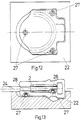
- Fig. 12 die untere Formschale mit den Zentrierzapfen in Draufsicht und
- Fig. 13 die untere Formschale im Schnitt mit eingelegtem rohem Absperrkeil.
- 1 is a front view of a blocking wedge carrying the slide shoes according to the invention with a rubber-elastic covering,
- 2 shows a cross section through the locking wedge according to line II-II of FIG. 1,
- 3 is a side view of the locking wedge according to FIGS. 1 and 2,
- 4 the slide shoe in plan view,
- Fig. 5 shows the shoe of Fig. 4 in Seitenan view,
- 6 shows the slide shoe according to FIGS. 4 and 5 in rear view,
- 7 shows the slide shoe according to FIG. 4 on an enlarged scale,
- 8 shows a locking wedge with another sliding block, partly in longitudinal section,
- 9 shows the closed mold in section,
- 10 is a plan view of the central part of the injection mold that carries the sliding shoes,
- 11 shows a section through the holding strip according to line XI-XI of FIG. 10 with the slide shoe attached,
- Fig. 12, the lower mold shell with the centering pin in plan view
- Fig. 13, the lower shell in section with an inserted raw shut-off wedge.
Der in den Fig. 1-3 dargestellte gummierte Absperrkeil 1 wird im wesentlichen aus dem rohen Gußeisenkörper 2 und der aufgespritzten gummielastischen Umhüllung 3 gebildet. Im Bereich der mit den Sitzflächen des Schiebergehäuses zusammenwirkenden Abdichtflächen ist der Gußeisenkörper 2 mit Nuten 4 versehen und die gummielastische Umhüllung 3 ist hier wulstartig verdickt, so daß der Absperrkeil 1 weichelastische Dichtstränge 5 aufweist. Der rohe Gußeisenkörper 2 ist auf seinen beiden Schmalseiten mit eingegossenen Führungsnuten 6 versehen, in die die Kunststoff-Gleitschuhe 7 fest eingesetzt sind.The rubberized shut-off
Die beiden Kunststoff-Gleitschuhe 7 sind im Querschnitt kleiner als die eingegossenen Führungsnuten 6, so daß zwischen dem Boden 8 der Führungsnut 6 und dem Boden 9 der Gleitschuhe 7 sowie zwischen den Seitenwänden 10 der Führungsnuten 6 und Seitenwänden 11 der Gleitschuhe 7 jeweils ein Spalt verbleibt, die zusammen den Hohlraum 12 ergeben, der beim Spritzen der gummielastischen Umhüllung 3 von der Spritzmasse 13 hinterfüllt wird. Nach dem Vulkanisierungsprozeß für die gummielastische Umhüllung 3 bildet auch die Hinterspritzmasse 13 eine feste elastische Gummischicht, durch die die Außenflächen 14 der Gleitschuhe 7 in den Führungsnuten 6 fest mit dem Gußkörper 2 verbunden sind. Die Kunststoff-Gleitschuhe 7 sind bis auf ihre an den Führungsleisten des nicht dargestellten Schiebergehäuses anliegenden Gleitflächen 15 von der gummielastischen Umhüllung 5 dicht umschlossen, so daß ein nahtfreier Übergang von der gummielastischen Umhüllung 3 zu den in der Hinterfüllschicht 13 eingebetteten Kunststoff-Gleitschuhen 7 besteht.The two
Wie die Fig. 4-7 zeigen, ist der Boden 9 der Kunststoff-Gleitschuhe 7 mit einer Anzahl Haltequerrippen 16 versehen. Durch diese Haltequerrippen sind die Gleitschuhe noch fester in der Hinterfüllschicht 13 eingebettet und verankert. Im Bereich zwischen den Haltequerrippen 1.6 weisen die Kunststoff-Gleitschuhe 7 abgerundete und abgeschrägte Übergänge 17 auf, damit die Hinterspritzmasse 13 die Haltequernuten 16 noch besser umfließen kann. Um einen ausreichenden Zulaufkanal für die Hinterspritzmasse 13 zu schaffen, ist in der Mitte des Bodens 8 der Führungsnuten 6 eine kleine Längsnut 18 von halbkreisförmigem Querschnitt in den rohen Absperrkeil 2 eingegossen, wie aus der Fig. 2 zu ersehen ist. Zum Halten der Gleitschuhe 7 in der Spritzform während des Hinterspritzvorganges sind die Schuhe an den Innenlängskanten mit Klemmnuten 19 versehen, in die entsprechende Vorsprünge der Spritzform schnapperartig eingreifen können.As shown in FIGS. 4-7, the
In der Fig. 8 ist eine andere Ausführungsform der Haltequerrippen 16 der Gleitschuhe 7 gezeigt. Die Zwischenräume zwischen den Haltequerrippen sind hier als schwalbenschwanzartige Hinterschneidungen 20 ausgebildet, damit sich eine noch feste Verankerung der Gleitschuhe 7 in der elastischen Verbindungsschicht 13 ergibt.Another embodiment of the holding
Die in der Fig. 9 gezeigte Spritzform 21 besteht aus der unteren Formschale 22, der oberen Formschale 23 und dem Mittelteil 24. Die beiden Formschalen 22 und 23 begrenzen jeweils eine Hälfte der Außenkonturen der aufzuspritzenden gummielastischen Umhüllung 3 des Absperrkeils 1. Der Mittelteil 24 der Spritzform 21 ist feststehend ausgebildet, während die obere Formschale 23 zum Einlegen des Absperrkeils nach oben abgenommen wird. Die untere Formschale 22 wird zum Einlegen des Absperrkeils in Pfeilrichtung parallel zum feststehenden Mittelteil 24 verschoben.The
Wie die Fig. 10 und 11 zeigen, ist der feststehende Mittelteil 24 mit Halteleisten 25 versehen, auf die die Gleitschuhe 7 aufgeklemmt sind. Zu diesem Zweck besitzen die Halteleisten 25 Vorsprünge 26, die in die Klemmnuten 19 der Gleitschuhe 7 schnapperartig eingreifen.As shown in FIGS. 10 and 11, the fixed
Die Fig. 12 zeigt die untere Formschale 22 mit den Formvertiefungen für die zu spritzende elastische Umhüllung in Draufsicht sowie die Anordnung der 3 Zentrierzapfen 27, die zur Lagefixierung des einzulegenden Absperrkeils vorgesehen sind. Während die Fig. 12 noch die leere Formhälfte ohne eingelegten Absperrkeil zeigt, ist der rohgegossene Absperrkeil 2 in der Fig. 13 bereits in die aus der Spritzform 21 herausgezogene untere Formhälfte 22 eingelegt. Hierbei greifen die Zentrierzapfen 27 in die am Absperrkeil vorgesehenen Zentriersacklöcher 28 ein und fixieren dadurch die Lage des Absperrkeils sowohl gegenüber der elastischen Umhüllung als auch gegenüber den im Mittelteil 24 eingesetzten Gleitschuhen 7. Durch diese Lagefixierung des rohen Absperrkeils 2 kommen die im Mittelteil 24 lagefixierten Gleitschuhe 7 beim Einschieben der unteren Formschale 22 in die Spritzform 21 zentrisch in den Führungsnuten 6 des Absperrkeils zu liegen.Fig. 12 shows the
Claims (10)
Priority Applications (1)
| Application Number | Priority Date | Filing Date | Title |
|---|---|---|---|
| AT84115252T ATE40586T1 (en) | 1983-12-14 | 1984-12-12 | WEDGE FOR GATE VALVE. |
Applications Claiming Priority (2)
| Application Number | Priority Date | Filing Date | Title |
|---|---|---|---|
| DE19833345133 DE3345133A1 (en) | 1983-12-14 | 1983-12-14 | LOCKING WEDGE FOR LOCKING VALVES |
| DE3345133 | 1983-12-14 |
Publications (3)
| Publication Number | Publication Date |
|---|---|
| EP0146112A2 EP0146112A2 (en) | 1985-06-26 |
| EP0146112A3 EP0146112A3 (en) | 1986-06-04 |
| EP0146112B1 true EP0146112B1 (en) | 1989-02-01 |
Family
ID=6216861
Family Applications (1)
| Application Number | Title | Priority Date | Filing Date |
|---|---|---|---|
| EP84115252A Expired EP0146112B1 (en) | 1983-12-14 | 1984-12-12 | Closure wedge for a gate valve |
Country Status (12)
| Country | Link |
|---|---|
| US (1) | US4629160A (en) |
| EP (1) | EP0146112B1 (en) |
| JP (1) | JPS60179576A (en) |
| AT (1) | ATE40586T1 (en) |
| CA (1) | CA1243294A (en) |
| DE (1) | DE3345133A1 (en) |
| DK (1) | DK160639C (en) |
| ES (1) | ES293844Y (en) |
| FI (1) | FI77310C (en) |
| NO (1) | NO161397C (en) |
| SE (1) | SE458300B (en) |
| ZA (1) | ZA849755B (en) |
Cited By (1)
| Publication number | Priority date | Publication date | Assignee | Title |
|---|---|---|---|---|
| RU209103U1 (en) * | 2021-04-15 | 2022-02-01 | Общество с ограниченной ответственностью "Завод нефтегазового оборудования "ТЕХНОВЕК" | GATE VALVE |
Families Citing this family (26)
| Publication number | Priority date | Publication date | Assignee | Title |
|---|---|---|---|---|
| DE3428485A1 (en) * | 1984-08-02 | 1986-02-20 | Bopp & Reuther Gmbh, 6800 Mannheim | LOCKING WEDGE FOR LOCKING VALVES |
| DK161781C (en) * | 1989-06-19 | 1992-01-20 | Avk Maskinfab | LOCK VALVE AND PROCEDURE FOR PREPARING A RELEVANT SHOOTER |
| US5704594A (en) * | 1995-04-11 | 1998-01-06 | Bw/Ip Internatinal, Inc. | Guided gate valve |
| US5657961A (en) * | 1995-04-18 | 1997-08-19 | Kalsi Engineering, Inc. | Flexible wedge gate valve |
| AT405758B (en) * | 1997-12-15 | 1999-11-25 | Hawle & Co E | SLIDING VALVE |
| DE19803589A1 (en) * | 1998-01-30 | 1999-08-12 | Voith Hydro Gmbh & Co Kg | Method for producing a component of a turbomachine |
| US6283446B1 (en) * | 1999-03-18 | 2001-09-04 | Suiken Technology Co., Ltd. | Gate valve system |
| GB0018222D0 (en) * | 2000-07-26 | 2000-09-13 | Market Linc Holdings Ltd | Valves |
| JP3886766B2 (en) | 2001-01-11 | 2007-02-28 | 富士機工株式会社 | Tilt and telescopic steering column device |
| UA78335C2 (en) * | 2002-06-27 | 2007-03-15 | Е. Хоул Арматуренверке Гмбх | Shutoff fitting |
| US6663079B1 (en) | 2002-07-18 | 2003-12-16 | Mcwane, Inc. | Resilient seat gate valve |
| FR2846392B1 (en) * | 2002-10-23 | 2005-09-02 | Saint Gobain Pont A Mousson | STOP CORNER, AND CORRESPONDING STOP VALVE |
| DE102005008290A1 (en) * | 2005-02-23 | 2006-08-24 | Rauch Landmaschinenfabrik Gmbh | Pneumatic spreading machine for e.g. seed, has distributor lines attached at circle-symmetrically distributed arranged outlets of distributor head, and wedges pointing to center of head with their vertex provided with guide at its base |
| GB0801562D0 (en) * | 2008-01-29 | 2008-03-05 | Woodward Peter J | Sealing system for gate valve |
| JP5253269B2 (en) * | 2009-03-31 | 2013-07-31 | 株式会社クボタ | Gate valve |
| CN102109044B (en) * | 2009-12-24 | 2015-06-17 | 泰科龙(上海)管道有限公司 | Non-rising stem gate valve |
| AT509083B1 (en) | 2010-01-14 | 2011-06-15 | E Hawle Armaturenwerke Gmbh | shut-off |
| JP2012030536A (en) * | 2010-07-30 | 2012-02-16 | Toshiba Corp | Casting mold and gas-insulated switchgear |
| US20120291877A1 (en) * | 2011-05-17 | 2012-11-22 | Meek Robert K | Gate valve |
| WO2013010546A1 (en) | 2011-07-15 | 2013-01-24 | Avk Holding A/S | Sliding valve member comprising guide means |
| CN102829205B (en) * | 2012-09-14 | 2014-01-01 | 陈建峰 | Anti-corrosive anti-pollution environment-friendly plastic brake valve with flexible seal and machining process thereof |
| EP2746629A1 (en) | 2012-12-21 | 2014-06-25 | AVK Holding A/S | Valve wedge for a slide valve |
| US9140368B2 (en) | 2013-03-15 | 2015-09-22 | Mueller International, Llc | Gate valve with track cleanout |
| CN103322294B (en) * | 2013-07-09 | 2015-10-28 | 芜湖市金贸流体科技股份有限公司 | A kind of inserted spool and manufacturing process thereof |
| PL232483B1 (en) * | 2014-03-12 | 2019-06-28 | Grundwaterstream Armaturen Gmbh W Organizacji | Gate valve head |
| WO2023031812A1 (en) * | 2021-08-31 | 2023-03-09 | Fucoli Somepal - Fundição De Ferro S.A. | Valve gate for a slide valve |
Citations (1)
| Publication number | Priority date | Publication date | Assignee | Title |
|---|---|---|---|---|
| DE2200472A1 (en) * | 1971-01-05 | 1972-07-20 | Mueller Co | Shut-off valve for fluid lines |
Family Cites Families (7)
| Publication number | Priority date | Publication date | Assignee | Title |
|---|---|---|---|---|
| US3045963A (en) * | 1959-07-17 | 1962-07-24 | Edward M Herrmann | Gate valve |
| US3763880A (en) * | 1969-11-28 | 1973-10-09 | Mueller Co | Gate valve structure |
| DE2110855C3 (en) * | 1971-03-08 | 1980-06-12 | Rheinisches Metallwerk Gmbh Armaturenfabrik, Metall- Und Eisengiesserei, 5000 Koeln | Process for the production of a shut-off body which can be used for a gate valve |
| US3837617A (en) * | 1973-04-19 | 1974-09-24 | Westinghouse Electric Corp | Gate valve |
| DE2843163A1 (en) * | 1978-10-04 | 1980-04-17 | Eisenwerk Roedinghausen Gmbh U | SLIDER FOR PIPELINES |
| US4313593A (en) * | 1979-02-20 | 1982-02-02 | Neptune Glenfield Limited | Gate valves |
| US4532957A (en) * | 1983-06-24 | 1985-08-06 | United States Pipe And Foundry Company | Guides for gate valves |
-
1983
- 1983-12-14 DE DE19833345133 patent/DE3345133A1/en active Granted
-
1984
- 1984-12-04 NO NO844821A patent/NO161397C/en unknown
- 1984-12-06 US US06/679,014 patent/US4629160A/en not_active Expired - Fee Related
- 1984-12-10 SE SE8406247A patent/SE458300B/en not_active IP Right Cessation
- 1984-12-11 FI FI844894A patent/FI77310C/en not_active IP Right Cessation
- 1984-12-12 EP EP84115252A patent/EP0146112B1/en not_active Expired
- 1984-12-12 AT AT84115252T patent/ATE40586T1/en active
- 1984-12-13 DK DK595684A patent/DK160639C/en not_active IP Right Cessation
- 1984-12-13 ES ES1984293844U patent/ES293844Y/en not_active Expired
- 1984-12-13 CA CA000469997A patent/CA1243294A/en not_active Expired
- 1984-12-14 ZA ZA849755A patent/ZA849755B/en unknown
- 1984-12-14 JP JP59263102A patent/JPS60179576A/en active Granted
Patent Citations (1)
| Publication number | Priority date | Publication date | Assignee | Title |
|---|---|---|---|---|
| DE2200472A1 (en) * | 1971-01-05 | 1972-07-20 | Mueller Co | Shut-off valve for fluid lines |
Cited By (1)
| Publication number | Priority date | Publication date | Assignee | Title |
|---|---|---|---|---|
| RU209103U1 (en) * | 2021-04-15 | 2022-02-01 | Общество с ограниченной ответственностью "Завод нефтегазового оборудования "ТЕХНОВЕК" | GATE VALVE |
Also Published As
| Publication number | Publication date |
|---|---|
| ES293844Y (en) | 1987-08-01 |
| SE8406247D0 (en) | 1984-12-10 |
| CA1243294A (en) | 1988-10-18 |
| DK595684A (en) | 1985-06-15 |
| DK160639B (en) | 1991-04-02 |
| ATE40586T1 (en) | 1989-02-15 |
| SE458300B (en) | 1989-03-13 |
| EP0146112A3 (en) | 1986-06-04 |
| EP0146112A2 (en) | 1985-06-26 |
| DK595684D0 (en) | 1984-12-13 |
| JPS60179576A (en) | 1985-09-13 |
| US4629160A (en) | 1986-12-16 |
| NO161397C (en) | 1989-08-09 |
| ZA849755B (en) | 1985-09-25 |
| ES293844U (en) | 1986-11-16 |
| DE3345133C2 (en) | 1988-03-03 |
| FI844894A0 (en) | 1984-12-11 |
| JPH0445710B2 (en) | 1992-07-27 |
| SE8406247L (en) | 1985-06-15 |
| NO844821L (en) | 1985-06-17 |
| DK160639C (en) | 1991-09-02 |
| FI77310B (en) | 1988-10-31 |
| DE3345133A1 (en) | 1985-09-26 |
| NO161397B (en) | 1989-05-02 |
| FI77310C (en) | 1989-02-10 |
| FI844894L (en) | 1985-06-15 |
Similar Documents
| Publication | Publication Date | Title |
|---|---|---|
| EP0146112B1 (en) | Closure wedge for a gate valve | |
| DE60316444T2 (en) | VALVE NODE GUIDANCE AND ALIGNMENT SYSTEM FOR A HOT CHANNEL IN AN INJECTION MOLDING DEVICE | |
| EP0171693B1 (en) | Gate valve | |
| DE2619666A1 (en) | METHOD OF MANUFACTURING A WEAR SEAL AND WEIR EQUIPPED WITH IT | |
| DE3206677C1 (en) | Process for the production of ring-shaped seals | |
| DE3209920C2 (en) | ||
| DE19617437A1 (en) | Elastomeric ring seal for use e.g. in collar fitting floor hole | |
| DE19815526B4 (en) | Linear guide with positive guidance of the cage | |
| DE2939601A1 (en) | POETRY | |
| DE3621870A1 (en) | PIPE CONNECTION | |
| DE2938366A1 (en) | Concrete pipe sections elastic joint sealing strip - has thin lamellae protruding from side pieces extending from central hollow profile | |
| DE2849779C2 (en) | Butterfly valve and process for its manufacture | |
| EP1517056A1 (en) | Guide with rolling elements | |
| EP0671536B1 (en) | Roller shutter profile, in particular for garage doors or roller doors | |
| DE2110855C3 (en) | Process for the production of a shut-off body which can be used for a gate valve | |
| DE2804645A1 (en) | PIPE COUPLING | |
| DE19750449C1 (en) | Producing cast component joining hollow component | |
| DE19911022C2 (en) | Sliding window for a motor vehicle | |
| EP0809054B1 (en) | Double acting sealing ring for gate-valve | |
| DE19609596A1 (en) | Linear bearing with adjustable play | |
| DE19641312A1 (en) | Frames for windows, doors, facades or the like | |
| DE19916249A1 (en) | Mold for use in a gas assisted injection molding system and adjustable overflow pin assembly for use therein | |
| DE19542696C2 (en) | Method of manufacturing radial roller bearing cages | |
| DE4101525A1 (en) | Seal between hollow concrete components - uses permanently plastic material partly filling one groove accommodating sealing strip | |
| DE4209204C1 (en) | Butt seal for sewer pipes with central coupling ring groove - has in each butt end formed concentric, flat grooves on either side of central groove |
Legal Events
| Date | Code | Title | Description |
|---|---|---|---|
| PUAI | Public reference made under article 153(3) epc to a published international application that has entered the european phase |
Free format text: ORIGINAL CODE: 0009012 |
|
| AK | Designated contracting states |
Designated state(s): AT BE CH FR GB IT LI LU NL |
|
| PUAL | Search report despatched |
Free format text: ORIGINAL CODE: 0009013 |
|
| AK | Designated contracting states |
Kind code of ref document: A3 Designated state(s): AT BE CH FR GB IT LI LU NL |
|
| 17P | Request for examination filed |
Effective date: 19861203 |
|
| 17Q | First examination report despatched |
Effective date: 19880203 |
|
| GRAA | (expected) grant |
Free format text: ORIGINAL CODE: 0009210 |
|
| AK | Designated contracting states |
Kind code of ref document: B1 Designated state(s): AT BE CH FR GB IT LI LU NL |
|
| REF | Corresponds to: |
Ref document number: 40586 Country of ref document: AT Date of ref document: 19890215 Kind code of ref document: T |
|
| ITF | It: translation for a ep patent filed |
Owner name: DE DOMINICIS & MAYER S.R.L. |
|
| GBT | Gb: translation of ep patent filed (gb section 77(6)(a)/1977) | ||
| ET | Fr: translation filed | ||
| PLBE | No opposition filed within time limit |
Free format text: ORIGINAL CODE: 0009261 |
|
| STAA | Information on the status of an ep patent application or granted ep patent |
Free format text: STATUS: NO OPPOSITION FILED WITHIN TIME LIMIT |
|
| PG25 | Lapsed in a contracting state [announced via postgrant information from national office to epo] |
Ref country code: LU Free format text: LAPSE BECAUSE OF NON-PAYMENT OF DUE FEES Effective date: 19891231 |
|
| 26N | No opposition filed | ||
| REG | Reference to a national code |
Ref country code: CH Ref legal event code: PFA Free format text: BOPP & REUTHER AKTIENGESELLSCHAFT |
|
| PGFP | Annual fee paid to national office [announced via postgrant information from national office to epo] |
Ref country code: NL Payment date: 19901231 Year of fee payment: 7 |
|
| NLS | Nl: assignments of ep-patents |
Owner name: BOPP & REUTHER AKTIENGESELLSCHAFT TE MANNHEIM, BON |
|
| PGFP | Annual fee paid to national office [announced via postgrant information from national office to epo] |
Ref country code: BE Payment date: 19911015 Year of fee payment: 8 |
|
| ITTA | It: last paid annual fee | ||
| PG25 | Lapsed in a contracting state [announced via postgrant information from national office to epo] |
Ref country code: NL Effective date: 19920701 |
|
| NLV4 | Nl: lapsed or anulled due to non-payment of the annual fee | ||
| PG25 | Lapsed in a contracting state [announced via postgrant information from national office to epo] |
Ref country code: BE Effective date: 19921231 |
|
| BERE | Be: lapsed |
Owner name: BOPP & REUTHER G.M.B.H. Effective date: 19921231 |
|
| PGFP | Annual fee paid to national office [announced via postgrant information from national office to epo] |
Ref country code: GB Payment date: 19971211 Year of fee payment: 14 |
|
| PGFP | Annual fee paid to national office [announced via postgrant information from national office to epo] |
Ref country code: CH Payment date: 19971219 Year of fee payment: 14 |
|
| PGFP | Annual fee paid to national office [announced via postgrant information from national office to epo] |
Ref country code: AT Payment date: 19971230 Year of fee payment: 14 |
|
| PG25 | Lapsed in a contracting state [announced via postgrant information from national office to epo] |
Ref country code: GB Free format text: LAPSE BECAUSE OF NON-PAYMENT OF DUE FEES Effective date: 19981212 Ref country code: AT Free format text: LAPSE BECAUSE OF NON-PAYMENT OF DUE FEES Effective date: 19981212 |
|
| PG25 | Lapsed in a contracting state [announced via postgrant information from national office to epo] |
Ref country code: LI Free format text: LAPSE BECAUSE OF NON-PAYMENT OF DUE FEES Effective date: 19981231 Ref country code: CH Free format text: LAPSE BECAUSE OF NON-PAYMENT OF DUE FEES Effective date: 19981231 |
|
| GBPC | Gb: european patent ceased through non-payment of renewal fee |
Effective date: 19981212 |
|
| REG | Reference to a national code |
Ref country code: CH Ref legal event code: PL |
|
| PGFP | Annual fee paid to national office [announced via postgrant information from national office to epo] |
Ref country code: FR Payment date: 20011227 Year of fee payment: 18 |
|
| PG25 | Lapsed in a contracting state [announced via postgrant information from national office to epo] |
Ref country code: FR Free format text: LAPSE BECAUSE OF NON-PAYMENT OF DUE FEES Effective date: 20030901 |
|
| REG | Reference to a national code |
Ref country code: FR Ref legal event code: ST |