EP0145837B1 - Bremsmotor mit Handbremslüftung - Google Patents
Bremsmotor mit Handbremslüftung Download PDFInfo
- Publication number
- EP0145837B1 EP0145837B1 EP84109325A EP84109325A EP0145837B1 EP 0145837 B1 EP0145837 B1 EP 0145837B1 EP 84109325 A EP84109325 A EP 84109325A EP 84109325 A EP84109325 A EP 84109325A EP 0145837 B1 EP0145837 B1 EP 0145837B1
- Authority
- EP
- European Patent Office
- Prior art keywords
- ring
- brake
- guideway
- brake drum
- motor
- Prior art date
- Legal status (The legal status is an assumption and is not a legal conclusion. Google has not performed a legal analysis and makes no representation as to the accuracy of the status listed.)
- Expired
Links
- 230000003014 reinforcing effect Effects 0.000 claims abstract 4
- 238000009423 ventilation Methods 0.000 description 5
- 238000004026 adhesive bonding Methods 0.000 description 1
- 238000001816 cooling Methods 0.000 description 1
- 238000011161 development Methods 0.000 description 1
- 230000018109 developmental process Effects 0.000 description 1
- 238000006073 displacement reaction Methods 0.000 description 1
- 239000000463 material Substances 0.000 description 1
- 239000002184 metal Substances 0.000 description 1
- 125000006850 spacer group Chemical group 0.000 description 1
Images

Classifications
-
- F—MECHANICAL ENGINEERING; LIGHTING; HEATING; WEAPONS; BLASTING
- F16—ENGINEERING ELEMENTS AND UNITS; GENERAL MEASURES FOR PRODUCING AND MAINTAINING EFFECTIVE FUNCTIONING OF MACHINES OR INSTALLATIONS; THERMAL INSULATION IN GENERAL
- F16D—COUPLINGS FOR TRANSMITTING ROTATION; CLUTCHES; BRAKES
- F16D59/00—Self-acting brakes, e.g. coming into operation at a predetermined speed
- F16D59/02—Self-acting brakes, e.g. coming into operation at a predetermined speed spring-loaded and adapted to be released by mechanical, fluid, or electromagnetic means
-
- F—MECHANICAL ENGINEERING; LIGHTING; HEATING; WEAPONS; BLASTING
- F16—ENGINEERING ELEMENTS AND UNITS; GENERAL MEASURES FOR PRODUCING AND MAINTAINING EFFECTIVE FUNCTIONING OF MACHINES OR INSTALLATIONS; THERMAL INSULATION IN GENERAL
- F16D—COUPLINGS FOR TRANSMITTING ROTATION; CLUTCHES; BRAKES
- F16D51/00—Brakes with outwardly-movable braking members co-operating with the inner surface of a drum or the like
-
- H—ELECTRICITY
- H02—GENERATION; CONVERSION OR DISTRIBUTION OF ELECTRIC POWER
- H02K—DYNAMO-ELECTRIC MACHINES
- H02K7/00—Arrangements for handling mechanical energy structurally associated with dynamo-electric machines, e.g. structural association with mechanical driving motors or auxiliary dynamo-electric machines
- H02K7/10—Structural association with clutches, brakes, gears, pulleys or mechanical starters
- H02K7/102—Structural association with clutches, brakes, gears, pulleys or mechanical starters with friction brakes
- H02K7/1021—Magnetically influenced friction brakes
- H02K7/1023—Magnetically influenced friction brakes using electromagnets
-
- F—MECHANICAL ENGINEERING; LIGHTING; HEATING; WEAPONS; BLASTING
- F16—ENGINEERING ELEMENTS AND UNITS; GENERAL MEASURES FOR PRODUCING AND MAINTAINING EFFECTIVE FUNCTIONING OF MACHINES OR INSTALLATIONS; THERMAL INSULATION IN GENERAL
- F16D—COUPLINGS FOR TRANSMITTING ROTATION; CLUTCHES; BRAKES
- F16D2121/00—Type of actuator operation force
- F16D2121/18—Electric or magnetic
- F16D2121/20—Electric or magnetic using electromagnets
- F16D2121/22—Electric or magnetic using electromagnets for releasing a normally applied brake
-
- F—MECHANICAL ENGINEERING; LIGHTING; HEATING; WEAPONS; BLASTING
- F16—ENGINEERING ELEMENTS AND UNITS; GENERAL MEASURES FOR PRODUCING AND MAINTAINING EFFECTIVE FUNCTIONING OF MACHINES OR INSTALLATIONS; THERMAL INSULATION IN GENERAL
- F16D—COUPLINGS FOR TRANSMITTING ROTATION; CLUTCHES; BRAKES
- F16D2127/00—Auxiliary mechanisms
- F16D2127/02—Release mechanisms
- F16D2127/04—Release mechanisms for manual operation
Definitions
- the present invention relates to a brake motor according to the preamble of claim 1.
- the invention is therefore based on the object of designing a brake motor in a simple manner so that a robust, functionally reliable, manually adjustable brake ventilation is possible at any time, without having to make major structural changes to the motor, without excessive effort, whereby tilting of the brake elements is avoided shall be.
- the design of the brake motor according to the invention has the advantageous consequence that the intended guidance of the brake elements does not permit their tilting. In this way, a uniform pressure can be exerted on the brake drum in an advantageous manner. This also allows ventilation without great effort.
- the brake motor shown in FIG. 1 usually has a shaft 1, which carries a rotor 2, which cooperates with a stator 3.
- the shaft 1 is supported in bearings 4 and 5, which in turn are supported in bearing plates 4 'and 5'.
- a brake drum 7 is attached, for. B. wedged, which serves to dissipate the heat, in particular also the braking heat, serving cooling vanes 8.
- a ring magnet 9 designed as a cross-sectionally U-profile-shaped ring magnet, in particular in a plane with the brake drum 7, is fixed and has two ring legs 10 and 11 projecting outwards.
- a magnetic coil 12 is arranged between the ring legs 10, 11 and is preferably fed with direct current, in which case one ring leg forms the north pole and the other the south pole.
- the ring magnet 9 can also be arranged rotatably and the brake drum 7 stand still.
- a leaf spring 13 which can be pressed by the leaf spring 13 against the brake drum 7 and brake elements 14, 15.
- the latter consist of an anchor plate 16 which is approximately curved to round the braking surface of the brake drum 7 and on which a brake pad 17 is fastened, for example by riveting or gluing.
- the braking elements 14, 15 are firmly connected to the leaf spring 13 by screws 18.
- outer shoe brake elements can also be provided and the braking surface is located on the outside of the brake drum 7.
- the leaf spring presses the brake elements 14, 15 against the brake drum 7 and brakes the motor and holds it in the holding position.
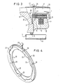
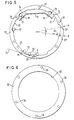
- Laterally axially projecting guide members 20 are attached to the brake elements 14, 15. These are preferably located on a circle 21 which is concentric with the shaft 1 (FIG. 5). Each guide member 20 lies in the region of an inclined slideway 22, which are attached in or on a ring 23 that can be rotated concentrically to the shaft 1. Due to the slope of the slideway 22, they form an angle ⁇ with a tangent 24 at the intersection with the circle 21. This is approximately 5 to 35 °, in particular 10 to 20 °.
- the ring 23 can be adjusted by hand from the outside via a hand lever 27 protruding through a slot 25 in the motor housing or a cover 26.
- the adjustment angle (3 preferably corresponds approximately to the length of a slideway 22, ie the guide members 20 are relative to the ring 23 from an end position A, in which a guide member 20 is located at one slideway end 22 'and not together with the slideway 22 can act in the other end position B, in which the slideway 22 in the area of the other slideway end 22 "pulls the associated guide member 20 and thus also the braking element 14 or 15 inwards, as indicated by the arrows of the dashed-line guide members 20, and the brake lining 17 lifts off the brake drum 7. As a result, the brake is released and the motor can be rotated.
- the ring 23 is provided in an intermediate space between the ring magnet 9 between the brake drum 7 and the end shield 5 '.
- the ring 23 consists of thin-walled material and can, for. B. be punched out of sheet metal. So that it is not deformed when the brake elements 14, 15 are released, it is firmly connected to a stiffening ring 29 by means of spacers 28, for example designed as bolts.
- the hand lever 27 can then, if necessary, additionally. be attached and is then preferably located between the ring 23 and the stiffening ring 29.
- the latter is designed as a carrier for the ring 23 and has a bearing point which is formed by a central sliding cutout 30. With the latter, it is rotatably arranged on a shoulder 31 of the ring magnet 9 or the bearing plate 5 'and secured against axial displacement.
- the lateral guidance is provided by the end shield 5 'and possibly also by the braking elements 14, 15 or by the ring magnet 9 (FIG. 3).
Landscapes
- Engineering & Computer Science (AREA)
- General Engineering & Computer Science (AREA)
- Physics & Mathematics (AREA)
- Electromagnetism (AREA)
- Mechanical Engineering (AREA)
- Power Engineering (AREA)
- Connection Of Motors, Electrical Generators, Mechanical Devices, And The Like (AREA)
- Braking Arrangements (AREA)
- Cage And Drive Apparatuses For Elevators (AREA)
Priority Applications (1)
| Application Number | Priority Date | Filing Date | Title |
|---|---|---|---|
| AT84109325T ATE44339T1 (de) | 1983-12-19 | 1984-08-06 | Bremsmotor mit handbremslueftung. |
Applications Claiming Priority (2)
| Application Number | Priority Date | Filing Date | Title |
|---|---|---|---|
| DE3345869A DE3345869A1 (de) | 1983-12-19 | 1983-12-19 | Bremsmotor mit handbremslueftung |
| DE3345869 | 1983-12-19 |
Publications (3)
| Publication Number | Publication Date |
|---|---|
| EP0145837A2 EP0145837A2 (de) | 1985-06-26 |
| EP0145837A3 EP0145837A3 (en) | 1986-06-04 |
| EP0145837B1 true EP0145837B1 (de) | 1989-06-28 |
Family
ID=6217361
Family Applications (1)
| Application Number | Title | Priority Date | Filing Date |
|---|---|---|---|
| EP84109325A Expired EP0145837B1 (de) | 1983-12-19 | 1984-08-06 | Bremsmotor mit Handbremslüftung |
Country Status (3)
| Country | Link |
|---|---|
| EP (1) | EP0145837B1 (da) |
| AT (1) | ATE44339T1 (da) |
| DE (2) | DE3345869A1 (da) |
Families Citing this family (4)
| Publication number | Priority date | Publication date | Assignee | Title |
|---|---|---|---|---|
| FR2695968B1 (fr) * | 1992-09-22 | 1994-12-23 | Aerospatiale | Dispositif à palier magnétique et à butée mécanique pour le positionnement d'un corps tournant par rapport à un corps statorique. |
| CA3062451A1 (en) * | 2017-06-01 | 2018-12-06 | Genesis Robotics And Motion Technologies Canada, Ulc | Magnetically actuated brake |
| CN112196917B (zh) * | 2020-10-19 | 2021-12-14 | 珠海格力电器股份有限公司 | 电磁制动器及电机 |
| CN113048169A (zh) * | 2021-03-30 | 2021-06-29 | 四川建安工业有限责任公司 | 一种制动鼓结构 |
Family Cites Families (5)
| Publication number | Priority date | Publication date | Assignee | Title |
|---|---|---|---|---|
| FR1118316A (fr) * | 1955-01-28 | 1956-06-04 | Moteurs Soc D Expl Des | Perfectionnement aux freins électro-magnétiques incorporés à des moteurs électriques |
| DE1255408B (de) * | 1964-11-13 | 1967-11-30 | Heemaf Ska Motorenwerk Ag | Hilfslueftvorrichtung fuer die Bremsbacken einer normalerweise elektromagnetisch lueftbaren Federdruck-Innenbackenbremse |
| DE1463888B2 (de) * | 1964-12-08 | 1972-01-05 | Heemaf S.K.A. Motorenwerk AG., 4600 Dortmund; Elektromotorische Antriebe GmbH, EMA, 5800 Hagen | Bremsmotor |
| DE1265842B (de) * | 1965-06-15 | 1968-04-11 | Helin Hagener Elek Zitaets Ind | Elektromotor mit elektromagnetisch und zusaetzlich von Hand lueftbarer Innenbackenbremse |
| NL163605C (nl) * | 1977-07-14 | 1980-09-15 | Heemaf Nv | Elektromagnetisch te lossen trommelrem. |
-
1983
- 1983-12-19 DE DE3345869A patent/DE3345869A1/de active Granted
-
1984
- 1984-08-06 DE DE8484109325T patent/DE3478838D1/de not_active Expired
- 1984-08-06 AT AT84109325T patent/ATE44339T1/de not_active IP Right Cessation
- 1984-08-06 EP EP84109325A patent/EP0145837B1/de not_active Expired
Also Published As
| Publication number | Publication date |
|---|---|
| DE3345869C2 (da) | 1989-06-29 |
| ATE44339T1 (de) | 1989-07-15 |
| EP0145837A2 (de) | 1985-06-26 |
| DE3478838D1 (en) | 1989-08-03 |
| DE3345869A1 (de) | 1985-07-04 |
| EP0145837A3 (en) | 1986-06-04 |
Similar Documents
| Publication | Publication Date | Title |
|---|---|---|
| DE69707674T2 (de) | Elektromagnetisch lösbare sicherheits-reibungsbremse | |
| DE19733169A1 (de) | Elektromagnetisch gelüftete Reibungs-Sicherheitsbremse mit zwei unabhängigen Bremskreisen | |
| EP0209943A1 (de) | Elektromotor mit Scheibenbremse | |
| DE4126196A1 (de) | Schwimmrahmen-teilbelagscheibenbremse fuer hochleistungsfahrzeuge | |
| DE1993752U (de) | Scheibenbremse. | |
| EP0222312B1 (de) | Federdruckbremse | |
| DE19629937C2 (de) | Elektrisch betätigte Kraftfahrzeug-Scheibenbremse, insbesondere in Schwimmsattel-Bauart | |
| DE2653861A1 (de) | Scheibenbremse | |
| DE3345869C2 (da) | ||
| DE2901784A1 (de) | Elektromagnetische scheibenbremse | |
| DE69904093T2 (de) | Scheibenbremsvorrichtung | |
| DE102016103176A1 (de) | Federdruckbremse | |
| DE19819141C2 (de) | Elektromagnetische Federdruckbremse | |
| DE102007014654A1 (de) | Bremsscheibenanordnung | |
| DE2841207A1 (de) | Elektromagnetisch gelueftete, federbetaetigte teilscheibenbremse | |
| DE19745775A1 (de) | Zentriereinrichtung für Bremssättel | |
| DE553164C (de) | Elektromagnetische Innenbackenbremse | |
| DE2721806C2 (de) | Lärmmindernde Feder für eine Scheibenbremse | |
| DE4106897A1 (de) | Elektromotor mit selbsttaetig wirkender bremse | |
| DE102006028289A1 (de) | Bremsvorrichtung für ein Schienenfahrzeug | |
| DE3906069A1 (de) | Elektromagnetbremse | |
| DE3026838C2 (de) | Elektromagnetisch betätigte Federdruckbremse | |
| DE2949506A1 (de) | Anschlag fuer den hebel einer mechanischen betaetigungsvorrichtung einer innenbacken-trommelbremse | |
| DE8336399U1 (de) | Bremsmotor mit Handbremslüftung | |
| DE20303060U1 (de) | Motoranbaubremse |
Legal Events
| Date | Code | Title | Description |
|---|---|---|---|
| PUAI | Public reference made under article 153(3) epc to a published international application that has entered the european phase |
Free format text: ORIGINAL CODE: 0009012 |
|
| AK | Designated contracting states |
Designated state(s): AT BE CH DE FR GB IT LI LU NL SE |
|
| 17P | Request for examination filed |
Effective date: 19850805 |
|
| PUAL | Search report despatched |
Free format text: ORIGINAL CODE: 0009013 |
|
| AK | Designated contracting states |
Kind code of ref document: A3 Designated state(s): AT BE CH DE FR GB IT LI LU NL SE |
|
| ITF | It: translation for a ep patent filed | ||
| RAP1 | Party data changed (applicant data changed or rights of an application transferred) |
Owner name: KATT-MOTORENFABRIK-FABRIK FOCK, OLBERG & CO. KG |
|
| RAP1 | Party data changed (applicant data changed or rights of an application transferred) |
Owner name: KATT-MOTOREN-FABRIK FOCK, OLBERG & CO. KG |
|
| 17Q | First examination report despatched |
Effective date: 19880429 |
|
| GRAA | (expected) grant |
Free format text: ORIGINAL CODE: 0009210 |
|
| AK | Designated contracting states |
Kind code of ref document: B1 Designated state(s): AT BE CH DE FR GB IT LI LU NL SE |
|
| PG25 | Lapsed in a contracting state [announced via postgrant information from national office to epo] |
Ref country code: SE Effective date: 19890628 Ref country code: NL Effective date: 19890628 Ref country code: IT Free format text: LAPSE BECAUSE OF FAILURE TO SUBMIT A TRANSLATION OF THE DESCRIPTION OR TO PAY THE FEE WITHIN THE PRESCRIBED TIME-LIMIT;WARNING: LAPSES OF ITALIAN PATENTS WITH EFFECTIVE DATE BEFORE 2007 MAY HAVE OCCURRED AT ANY TIME BEFORE 2007. THE CORRECT EFFECTIVE DATE MAY BE DIFFERENT FROM THE ONE RECORDED. Effective date: 19890628 Ref country code: GB Effective date: 19890628 Ref country code: FR Free format text: THE PATENT HAS BEEN ANNULLED BY A DECISION OF A NATIONAL AUTHORITY Effective date: 19890628 Ref country code: BE Effective date: 19890628 |
|
| REF | Corresponds to: |
Ref document number: 44339 Country of ref document: AT Date of ref document: 19890715 Kind code of ref document: T |
|
| REF | Corresponds to: |
Ref document number: 3478838 Country of ref document: DE Date of ref document: 19890803 |
|
| PG25 | Lapsed in a contracting state [announced via postgrant information from national office to epo] |
Ref country code: AT Effective date: 19890806 |
|
| PG25 | Lapsed in a contracting state [announced via postgrant information from national office to epo] |
Ref country code: LU Free format text: LAPSE BECAUSE OF NON-PAYMENT OF DUE FEES Effective date: 19890831 Ref country code: LI Effective date: 19890831 Ref country code: CH Effective date: 19890831 |
|
| PGFP | Annual fee paid to national office [announced via postgrant information from national office to epo] |
Ref country code: DE Payment date: 19891029 Year of fee payment: 6 |
|
| EN | Fr: translation not filed | ||
| NLV1 | Nl: lapsed or annulled due to failure to fulfill the requirements of art. 29p and 29m of the patents act | ||
| GBV | Gb: ep patent (uk) treated as always having been void in accordance with gb section 77(7)/1977 [no translation filed] | ||
| REG | Reference to a national code |
Ref country code: CH Ref legal event code: PL |
|
| PLBE | No opposition filed within time limit |
Free format text: ORIGINAL CODE: 0009261 |
|
| STAA | Information on the status of an ep patent application or granted ep patent |
Free format text: STATUS: NO OPPOSITION FILED WITHIN TIME LIMIT |
|
| 26N | No opposition filed | ||
| PG25 | Lapsed in a contracting state [announced via postgrant information from national office to epo] |
Ref country code: DE Effective date: 19910501 |