EP0145822B1 - Process and apparatus for drying moist products, in particular mixtures containing clay - Google Patents
Process and apparatus for drying moist products, in particular mixtures containing clay Download PDFInfo
- Publication number
- EP0145822B1 EP0145822B1 EP83402454A EP83402454A EP0145822B1 EP 0145822 B1 EP0145822 B1 EP 0145822B1 EP 83402454 A EP83402454 A EP 83402454A EP 83402454 A EP83402454 A EP 83402454A EP 0145822 B1 EP0145822 B1 EP 0145822B1
- Authority
- EP
- European Patent Office
- Prior art keywords
- products
- stream
- tunnel
- accordance
- gas stream
- Prior art date
- Legal status (The legal status is an assumption and is not a legal conclusion. Google has not performed a legal analysis and makes no representation as to the accuracy of the status listed.)
- Expired
Links
Images


Classifications
-
- B—PERFORMING OPERATIONS; TRANSPORTING
- B28—WORKING CEMENT, CLAY, OR STONE
- B28B—SHAPING CLAY OR OTHER CERAMIC COMPOSITIONS; SHAPING SLAG; SHAPING MIXTURES CONTAINING CEMENTITIOUS MATERIAL, e.g. PLASTER
- B28B11/00—Apparatus or processes for treating or working the shaped or preshaped articles
- B28B11/24—Apparatus or processes for treating or working the shaped or preshaped articles for curing, setting or hardening
- B28B11/243—Setting, e.g. drying, dehydrating or firing ceramic articles
-
- C—CHEMISTRY; METALLURGY
- C04—CEMENTS; CONCRETE; ARTIFICIAL STONE; CERAMICS; REFRACTORIES
- C04B—LIME, MAGNESIA; SLAG; CEMENTS; COMPOSITIONS THEREOF, e.g. MORTARS, CONCRETE OR LIKE BUILDING MATERIALS; ARTIFICIAL STONE; CERAMICS; REFRACTORIES; TREATMENT OF NATURAL STONE
- C04B33/00—Clay-wares
- C04B33/30—Drying methods
-
- F—MECHANICAL ENGINEERING; LIGHTING; HEATING; WEAPONS; BLASTING
- F26—DRYING
- F26B—DRYING SOLID MATERIALS OR OBJECTS BY REMOVING LIQUID THEREFROM
- F26B3/00—Drying solid materials or objects by processes involving the application of heat
- F26B3/32—Drying solid materials or objects by processes involving the application of heat by development of heat within the materials or objects to be dried, e.g. by fermentation or other microbiological action
- F26B3/34—Drying solid materials or objects by processes involving the application of heat by development of heat within the materials or objects to be dried, e.g. by fermentation or other microbiological action by using electrical effects
- F26B3/343—Drying solid materials or objects by processes involving the application of heat by development of heat within the materials or objects to be dried, e.g. by fermentation or other microbiological action by using electrical effects in combination with convection
-
- H—ELECTRICITY
- H05—ELECTRIC TECHNIQUES NOT OTHERWISE PROVIDED FOR
- H05B—ELECTRIC HEATING; ELECTRIC LIGHT SOURCES NOT OTHERWISE PROVIDED FOR; CIRCUIT ARRANGEMENTS FOR ELECTRIC LIGHT SOURCES, IN GENERAL
- H05B6/00—Heating by electric, magnetic or electromagnetic fields
- H05B6/64—Heating using microwaves
- H05B6/78—Arrangements for continuous movement of material
-
- H—ELECTRICITY
- H05—ELECTRIC TECHNIQUES NOT OTHERWISE PROVIDED FOR
- H05B—ELECTRIC HEATING; ELECTRIC LIGHT SOURCES NOT OTHERWISE PROVIDED FOR; CIRCUIT ARRANGEMENTS FOR ELECTRIC LIGHT SOURCES, IN GENERAL
- H05B2206/00—Aspects relating to heating by electric, magnetic, or electromagnetic fields covered by group H05B6/00
- H05B2206/04—Heating using microwaves
- H05B2206/046—Microwave drying of wood, ink, food, ceramic, sintering of ceramic, clothes, hair
-
- Y—GENERAL TAGGING OF NEW TECHNOLOGICAL DEVELOPMENTS; GENERAL TAGGING OF CROSS-SECTIONAL TECHNOLOGIES SPANNING OVER SEVERAL SECTIONS OF THE IPC; TECHNICAL SUBJECTS COVERED BY FORMER USPC CROSS-REFERENCE ART COLLECTIONS [XRACs] AND DIGESTS
- Y02—TECHNOLOGIES OR APPLICATIONS FOR MITIGATION OR ADAPTATION AGAINST CLIMATE CHANGE
- Y02P—CLIMATE CHANGE MITIGATION TECHNOLOGIES IN THE PRODUCTION OR PROCESSING OF GOODS
- Y02P40/00—Technologies relating to the processing of minerals
- Y02P40/60—Production of ceramic materials or ceramic elements, e.g. substitution of clay or shale by alternative raw materials, e.g. ashes
Definitions
- the invention relates to a method and an installation for drying wet products; it applies in particular but not exclusively to dry mixtures based on clays which are presented either in the form of shaped products, or in the state of crude masses.
- drying process very commonly used to dry products or wet masses consists in moving these products in drying tunnels, which are traversed by hot air against the flow of the direction of advancement of the materials.
- This counter-current ventilation is to avoid "crusting" of the products on the surface; this phenomenon which occurs if the products are subjected suddenly to a hot and dry flow, has the serious consequence, on the one hand, of preventing a homogeneous and complete drying of the products (by obstructing the migration of the water from the heart to the surface of the products and by trapping this water inside the said products), on the other hand, to cause cracks and breaks of the products on the surface due to the sudden rise in the vapor pressure of water near the crusty surface.
- the present invention relates to an improved drying process and proposes to significantly improve the energy balance of the above-mentioned drying processes and to considerably reduce their durations, while eliminating the risks of crusting on the surface of the products to be dried.
- Another objective of the invention is to provide a drying installation making it possible to implement said process with great flexibility of adaptation to the envisaged application.
- hygrometry of a gas flow, is meant the ratio of the effective pressure of the water vapor contained in this flow, to the value of the maximum pressure of saturated vapor under the same temperature conditions.
- phases (d) and (e) can be renewed, one or more times, the products then being subjected, after the above-mentioned phase (e), at least once to phases (d ') and (e ') identical to phases (d) and (e).
- phase (a) by the combination of radiation and ventilation consist, on the one hand, in a strong migration of water from the core of the products towards their surface, on the other hand, by a gradual warming up of the products internally and on the surface, and finally by initiating evaporation at the surface.
- the strong migration of water to the surface and the heating both on the surface and at the heart of the products eliminates any risk of crusting.
- Phase (b) consists of ventilation with less hot air, which causes effective evaporation of the water that migrated to the surface during the previous phase; this phase does not create any risk of crusting due to the milder temperature of the air flow and the residual migration which remains inside the products after the end of the previous phase. At the end of this phase (b), the products are at temperature and the risks of crusting and cracking are much lower.
- Phase (c) takes advantage of this lower propensity for crusting and cracking to extract an additional fraction of the water with air that is significantly hotter and drier than that of the previous phase.
- the breakdowns of phases (a), (b) and (c) make it possible to make the best use of the radiation effect of phase (a) without causing crusting or cracking phenomena.
- Phase (d) which includes a new irradiation, generates a new migration of water from the heart to the surface of the products; this new irradiation avoids a lowering of the drying efficiency, as would be the case if it was continued only by means of hot air.
- Phase (e) causes evaporation of the water which has migrated to the previous phase or which is in the process of migration by the effect of persistence.
- phase (a), (b), (c), (d), (e) and where appropriate (d ') and (e'), which combine microwave irradiation and specific ventilation allows achieve an extremely efficient homogeneous drying with moderate energy consumption and much shorter durations than in conventional counter-current processes (a few minutes to a few tens of minutes) and this, without risk of cracking for the products.
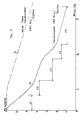
- FIG. 2 which will be commented on later, illustrates by way of comparison, on the one hand, a drying diagram a according to the method of the invention implemented under the conditions defined above, on the other hand, a diagram ⁇ drying using a counter-current process.
- the process of the invention involves an overall energy consumption about half that of the conventional process against the current and requires a time of the order of 4 times less important than the conventional counter-current process.
- Such performance is extremely important in practice since, for equal production, it allows for less costly installations, which pay off much more quickly.
- This mode of implementation in which the first ventilation flow can be obtained by deriving a fraction of the second flow makes it possible to improve the energy balance of the process, while reducing the cost of the necessary equipment (in particular due to the presence of a single hot air generator).
- the invention extends to an installation for drying wet products, with a view to implementing the method defined above.
- the shape of the tunnel from its entry to its exit can be diverse: rectilinear tunnel, tunnel with several contiguous sections juxtaposed on the same level, tunnel with several contiguous sections superimposed on different levels, tunnel in the form of a loop located in a plane vertical or horizontal.
- the conveyor can be of any known type, in particular an endless belt conveyor or a swing conveyor.
- the drying installation comprises a tunnel 1 delimiting an interior cavity extending between an inlet for products la and an outlet 1b; in the example, the tunnel 1 is straight and extends over a total length of the order of 18 m.
- the tunnel 1 is equipped with an endless belt conveyor 2 having an upper active strand 2a which moves between the entrance and the exit of the tunnel.
- This endless belt 2 is of a type known per se, with non-deformable mesh of glass fibers, coated with polytetrafluoroethylene, so as to be transparent with respect to microwave electromagnetic waves.
- This mat slides on glass tubes or other material, transparent to microwave waves and having a low coefficient of friction; it is driven by a variable speed drive making it possible to adjust the speed of translation of the products to be dried in a range between 0.1 m / min and 5 m / min.
- air stop means 3 of conventional type, capable of authorizing the passage of the belt 2 and of the products and, downstream, of filter means 4 forming a barrier to the passage of microwave waves.
- air stop means 3 there opens a sheath 5 for blowing hot air, called a secondary blowing sheath, which blows into the tunnel cavity a first flow of hot ventilation air.
- a first microwave wave generator 6 Downstream of the filtering means 4, a first microwave wave generator 6 is arranged, adapted to irradiate the internal cavity of the tunnel in an area Z, which is co-ventilated by the first ventilation flow and can have in l 'example a length of the order of 2 m.
- This generator is composed of several magnetrons and applicators, distributed along said zone. Its power is adapted to generate a microwave nemen rayon- t such that the power density at the core of the products is between 0.2 and 5 watts / cm 3 and can be adjusted within this range; the frequency of the microwave radiation is a usual industrial frequency (in particular 2450 Megahertz).
- the generator 6 is associated with means for standardizing the electromagnetic field inside the tunnel cavity; these means can take various known forms and an example will be described later.
- zone Z Downstream of zone Z "the products move along a zone Z 2 of length on the order of 2 m, where they are no longer irradiated and are ventilated cocurrently by the first ventilation flow after its passage along zone Z 1 ; in this zone Z 2 , this flow is therefore less hot and more humid than in zone Z 1 .
- the tunnel is equipped with an air extraction duct 7 provided with an extraction fan 8.
- the tunnel then comprises a zone Z 3 extending between the sheath 7 and a bypass sheath 9 provided with a fan 10.
- the sheath 9 draws from the tunnel a derivative flow, consisting of a fraction of a second ventilation flow which is blown into the tunnel near its exit 1b, as we will see later.
- the sheath 9 is connected to the secondary blowing sheath 5 so that the first ventilation flow is constituted by the fraction derived from the second flow.
- the remaining fraction of the second flow circulates against the current along the zone Z 3 before being sucked at the same time as the first flow in the extraction sheath 7.
- the zone Z 3 can have a length of the order 3 m.
- the tunnel comprises a second microwave generator 11, adapted to irradiate its internal cavity on an area Z4 which in the example may be 2 m in length; this zone Z 4 is ventilated against the current by the first aforementioned ventilation flow.
- This generator composed like the previous one by magnetrons and applicators distributed along the zone Z 4 is adapted to generate in the heart of the products a power density of the same order as before, adjustable over a range of 0.2 to 5 wattfcm 3 ; this generator is associated, like the previous one, with means for standardizing the electromagnetic field inside the tunnel cavity.
- the products move along a zone Z, of length on the order of 5 m, where they are no longer irradiated and are ventilated against the current by the second ventilation flow.
- This second ventilation flow is blown into the tunnel by a main blowing duct 12 located in the vicinity of its outlet 1b between means 13 for filtering microwave waves (identical to means 4) and downstream means 14 for stopping the air (identical to means 3).
- the second ventilation flow is generated by a dry hot air generator 15, the outlet of which is connected to the main supply duct 12.
- This generator has an inlet 15a receiving fresh air and an inlet 15b connected to the duct extraction 7 for the recycling of part of the extracted air.
- An extraction chimney 16 and a register 17 make it possible to reject an adjustable part of the air extracted by the extraction sheath 7.
- the bypass (9, 10) and the extraction (7, 8) are adapted so that the derived flow (first ventilation flow) has a speed v, of scanning of the products along the zones Z 1 and Z 2 such that 1 m / s ⁇ v 1 ⁇ 5 m / s (the speed V2 of scanning of the products by the remaining fraction of the flow along the zone Z 3 is of course substantially equal to Vv 1 ).
- the downstream section of counter-current extends over a length more than twice as long as that of the upstream section of co-current; in practice, depending on the application, the length of this counter-current section will be adjusted in a range from 1.5 to 5 times greater than that of the co-current section, the upper fraction of this range corresponding to an installation having several zones Z 4 and Z 5 arranged successively (by couple: irradiated and ventilated zone followed by a ventilated, non-irradiated zone).
- the total duration of the drying cycle is therefore in the example 14 '; the overall energy consumption (thermal and mechanical energy, microwave energy) is 1,700 Kcal / kg of evaporated water.
- the curve a of FIG. 2 illustrates as a function of time the evolution of the average humidity rate of the products: the curve (3 is a curve of the same type in the case of a conventional drying against the current in a tunnel of same dimension, in which the characteristics of the flow against the current have been adjusted to obtain the same end state of the products.
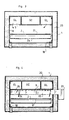
- FIGS. 3, 4, 5, 6, 7, 8 and 9 show a preferred embodiment of the installation described above.
- FIGS. 3, 4, 5, 6, 7 and 8 are cross-sections through six offset vertical planes, one A at the level of the secondary air supply 5, another B at the level of the zone Z 1 comprising the microwave generator 6 ( or zone Z 4 comprising the generator 11), another C at the level of zone Z 2 (or zones Z 3 and Z 5 ), another D at the level of extraction 7, another E at the level of the branch 9, finally another F at the main blowing 12.
- the tunnel is formed by a frame 18 which holds a quadrangular sheet 19, surrounded by a layer of heat-insulating material 20.
- the blowing ducts are inserted in the tunnel and occupy the upper part of this one. In the example, there are three of them, separated by partitions: a central duct G e which serves, in this embodiment, as main blowing duct 14, and two lateral ducts G L which serve as blowing duct Secondary 5.
- a free volume allows the insertion of a radiating module in the zones Z 1 and Z 4 , as shown in FIG. 4; the carpet 2 is located below, its useful upper strand being supported by the rollers 21 already mentioned.
- Figure 9 shows the air flows in said tunnel. It should be noted that means (not shown) are provided in the cavity where the carpet circulates to guide the air so as to bring it through the products in order to obtain a good sweeping thereof (flaps of '' stop and vertical recovery ducts on the sides).
- FIG. 3 shows, in the vicinity of the entrance, the passage of the first ventilation flow (derived flow) from the lateral ducts G L towards the tunnel cavity thanks to a light which these ducts have on their underside.
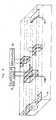
- FIG. 4 illustrates the arrangement of a radiating module at the level of the zone Z l .
- This module includes a wave applicator formed by a transverse waveguide 22 (straight or having meanders), with radiating slots on its underside.
- This guide is subject to the output of a magnetron 23 called to come and be disposed on the side of the tunnel.
- the guide 22 is inserted into the tunnel through an appropriate opening which the latter has on one side.
- the guide 22 is equipped with a mechanical system for standardizing the electromagnetic field, constituted in the example by two oscillating metal plates such as 24, driven in a pendulum movement by a slow motor, of low power 25 through 'an eccentric system.
- a meandering guide In the case of a meandering guide, it is welded to a lower plate, open at its slots, plate integral with the supply magnetron.
- FIG. 5 shows the tunnel at the level of the ventilated zone Z 2 .
- Figure 6 shows the tunnel at the extraction level; humidified air from, on the one hand, from the upstream section of co-current, on the other hand, from the downstream section of counter-current, is drawn upwards through the central duct G e by the fan 8 towards the hot air generator 15 or the chimney extraction 16; the central sheath G e is closed at this level by two walls to guide the air vertically.
- Figure 7 shows the tunnel at branch 9; a fraction of the air coming from the zone Z 4 is sucked upwards through the lateral ducts G L by the fan 10 which discharges it upstream in said lateral ducts; these are closed at this level by two walls and comprise an upward passage light between said walls and a downward passage light upstream of said walls.
- Figure 8 shows the tunnel in the vicinity of its exit 1b; the air leaving the hot air generator is discharged at the outlet of the latter in the central duct G c , which is open towards the tunnel cavity. at its end near the exit; the air thus passes in the downward direction in this cavity where it flows against the flow in the zone Z 5, and Z 4, Z 3 finally to the fraction res - aunt flow.
- FIG. 10 schematically shows an alternative installation in which the products move along two superimposed tunnels, surrounded as previously by thermal insulation.
- Each tunnel is equipped with an endless belt, the upper useful strands of these belts progressing in opposite directions so that the outlet of the installation is located above its entrance.
- an ascending member 26 of the conventional type makes it possible to continuously transfer the products from one carpet to another.
- the product journey takes place as previously along co-current zones Z 1 and Z 2 and counter-current zones; in the example, these counter-current zones comprise a zone Z 3 as already defined and three pairs of zones (Z 4 , Z 5 ), (Z ' 4 , Z' 5 ) and (Z " 4 , Z" s) analogous to zones Z 4 and Z 5 already defined.
- Zones Z 1 , Z 2 , Z 3 , Z4 and Z 5 are located along the lower tunnel, zones Z '4 , Z' 5 and Z " 4 and Z" 5 being located along the upper tunnel so that the counter-current section is much longer than previously.
- the zones Z 5 , Z ' 6 and Z " 5 are supplied with air under the same conditions of temperature and hygrometry, thanks to diversions by the lateral ducts G L.
- FIG. 10 illustrates the air flows and the positions respective areas.
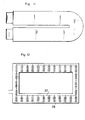
- FIG. 11 illustrates another embodiment in which two tunnels are juxtaposed on the same level. At one end, a transfer member circulates the products from the carpet of one tunnel through 180 ° to that of the other tunnel.
- the succession of zones Z l , Z 2, etc. is similar to that already described.
- FIG. 12 illustrates another embodiment in which the products are transported in a tunnel forming a closed loop in a vertical plane, by a swing conveyor 27.
- Each swing comprises a series of superimposed trays 28, on each of which are arranged the products in monolayer.
- swings are made of transparent materials with microwave waves.
- the products pass as before in front of waveguides, preferably placed in vertical planes, along one side of the tunnel, in order to uniformly expose all the trays of a swing.
- thermometric and hygrometric probes making it possible to control, and if necessary regulate, the characteristics of the air flows.
Abstract
Description
L'invention concerne un procédé et une installation pour le séchage de produits humides; elle s'applique en particulier mais non exclusivement pour sécher des mélanges à base d'argiles se présentant soit sous la forme de produits façonnés, soit à l'état de masses brutes.The invention relates to a method and an installation for drying wet products; it applies in particular but not exclusively to dry mixtures based on clays which are presented either in the form of shaped products, or in the state of crude masses.
Un type de procédé de séchage très couramment mis en oeuvre pour sécher des produits ou masses humides consiste à déplacer ces produits dans des tunnels de séchage, qui sont parcourus par de l'air chaud à contre-courant du sens d'avancement des matières.One type of drying process very commonly used to dry products or wet masses consists in moving these products in drying tunnels, which are traversed by hot air against the flow of the direction of advancement of the materials.
Cette ventilation à contre-courant a pour but essentiel d'éviter le "croûtage" des produits en surface; ce phénomène qui se produit si l'on soumet les produits brutalement à un flux chaud et sec, a pour grave conséquence, d'une part, d'empêcher un séchage homogène et complet des produits (en faisant obstacle à la migration de l'eau du coeur vers la surface des produits et en emprisonnant cette eau à l'intérieur desdits produits), d'autre par, de provoquer des fissures et cassures des produits en surface en raison de l'élévation brusque de la tension de vapeur d'eau au voisinage de la surface croûtée.The main purpose of this counter-current ventilation is to avoid "crusting" of the products on the surface; this phenomenon which occurs if the products are subjected suddenly to a hot and dry flow, has the serious consequence, on the one hand, of preventing a homogeneous and complete drying of the products (by obstructing the migration of the water from the heart to the surface of the products and by trapping this water inside the said products), on the other hand, to cause cracks and breaks of the products on the surface due to the sudden rise in the vapor pressure of water near the crusty surface.
Dans le séchage à contre-courant, l'air chaud et sec se refroidit et se charge progressivement d'humidité en remontant les produits de sorte que ces derniers sont soumis à une action d'échauffement et de dessication progressive évitant le croûtage. Ce type de séchage à contre-courant constitue actuellement sur le plan industriel de meilleur compromis entre la recherche d'une évacuation aussi économique que possible de l'eau contenue dans les produits et la necessité de supprimer les phénomènes de croûtage qui font obstacle à cette évacuation.In countercurrent drying, the hot, dry air cools and gradually becomes charged with moisture by raising the products so that the latter are subjected to a progressive heating and drying action, preventing crusting. At the industrial level, this type of countercurrent drying currently constitutes the best compromise between the search for as economical an evacuation of the water contained in the products and the need to remove the crusting phenomena which hinder this. evacuation.
Toutefois, ces procédés à contre-courant requièrent des durées de séchage très élevées, de l'ordre de quelques heures à quelques dizaines d'heures; une réduction des durées de séchage est extrêmement difficile à obtenir en pratique dans ce type de technique, car elle entraîne des risques de croûtage et surtout accroît très fortement les consommations énergétiques. Par exemple, à l'heure actuelle, les procédés à contre-courant les plus performants mis en oeuvre pour sécher des carreux constitués par des mélanges à base d'argile en vue de l'obtention de carreux en céramique, exigent des durées au moins égales à 1,5 heure à 2 heures et conditionnent des consommations énergétiques supérieures à 3 000 kcal par kg d'eau enlevée.However, these counter-current processes require very long drying times, of the order of a few hours to a few tens of hours; a reduction in drying times is extremely difficult to obtain in practice in this type of technique, since it involves risks of crusting and above all very strongly increases energy consumption. For example, at present, the most efficient counter-current processes implemented for drying tiles consisting of clay-based mixtures with a view to obtaining ceramic tiles, require durations at least equal to 1.5 hours to 2 hours and condition energy consumption greater than 3000 kcal per kg of water removed.
Ces limitations de performances proviennent de la très faible efficacité du flux à contre-courant: en effet, le long du parcours.des produits, le taux d'humidité et la température, d'une part des produits, d'autre par du flux d'air varient dans le même sens de sorte que le gradient hygrométrique et le gradient de température demeurent toujours relativement faibles tout le long du tunnel de séchage.These performance limitations stem from the very low efficiency of the countercurrent flow: in fact, along the course of the products, the humidity and temperature, on the one hand of the products, on the other hand by the flow air flow in the same direction so that the humidity gradient and the temperature gradient always remain relatively low throughout the drying tunnel.
A titre d'exemple d'un procédé de ce genre, on peut faire référence à celui décrit dans le FR-A-2.304.045 où le produit humide à sécher est soumis successivement à des flux de gaz chauds à températures différentes.By way of example of a process of this kind, reference may be made to that described in FR-A-2,304,045 where the wet product to be dried is successively subjected to hot gas flows at different temperatures.
De même et selon un autre procédé, on connaît par exemple par le FR-A-912895, un procédé de séchage utilisant un courant à haute fréquence, avec ventilation simultanée puis subséquente au moyen de flux gazeux chauds. Mais de tels procédés où deux phases de séchage distinctes sont effectuées consécutivement présentent des rendements médiocres et nécissitent une consommation d'enérgie prohibitive.Similarly and according to another method, there is known for example from FR-A-912895, a drying method using a high frequency current, with simultaneous and then subsequent ventilation by means of hot gas flows. However, such processes where two distinct drying phases are carried out consecutively have poor yields and require prohibitive energy consumption.
La présente invention vise un procédé de séchage perfectionné et se propose d'améliorer notablement le bilan énergétique des procédés de séchage sus-évoqués et d'en réduire considérablement les durées, tout en écartant les risques de croûtage en surface des produits à sécher.The present invention relates to an improved drying process and proposes to significantly improve the energy balance of the above-mentioned drying processes and to considerably reduce their durations, while eliminating the risks of crusting on the surface of the products to be dried.
Un autre objectif de l'invention est de fournir une installation de séchage permettant de mettre en oeuvre ledit procédé avec une grande souplesse d'adaptation à l'application envisagée.Another objective of the invention is to provide a drying installation making it possible to implement said process with great flexibility of adaptation to the envisaged application.
A cet effet, le procédé de séchage conforme à l'invention consiste à soumettre successivement les produits humides à sécher aux phases successives de traitement suivantes:
- (a) exposer les produits à un rayonnement électromagnétique hyperfréquence et, simultanément, les ventiler au moyen d'un flux gazeux chaud et non saturé,
- (b) ventiler ensuite lesdits produits au moyen d'un flux gazeux chaud et non saturé, de température moyenne inférieure à celle du flux de la phase (a),
- (c) ventiler ensuite lesdits produits au moyen d'un flux gazeux chaud et non saturé, de température moyenne supérieure à celle du flux de la phase (b) et d'hygrométrie inférieure à celle dudit flux,
- (d) exposer ensuite les produits à un rayonnement électromagnétique hyperfréquence et, simultanément, les ventiler au moyen d'un flux gazeux chaud et non saturé, de température moyenne supérieure à celle du flux de la phase (a) et d'hygrométrie inférieure à celle dudit flux,
- (e) ventiler ensuite lesdits produits au moyen d'un flux gazeux chaud et non saturé, de température moyenne supérieure à celle du flux de la phase (d) et d'hygrométrie inférieure à celle dudit flux.
- (a) exposing the products to microwave electromagnetic radiation and, simultaneously, ventilating them by means of a hot and unsaturated gas flow,
- (b) then ventilating said products by means of a hot and unsaturated gas flow, of average temperature lower than that of the flow of phase (a),
- (c) then ventilating said products by means of a hot and unsaturated gas flow, with an average temperature higher than that of the flow in phase (b) and with a hygrometry lower than that of said flow,
- (d) then exposing the products to microwave electromagnetic radiation and, simultaneously, ventilating them by means of a hot and unsaturated gas flow, of average temperature greater than that of the flow of phase (a) and of hygrometry below that of said flow,
- (e) then ventilating said products by means of a hot and unsaturated gas flow, of average temperature greater than that of the flow of phase (d) and of hygrometry lower than that of said flow.
Par "hygromètrie" d'un flux gazeux, on entend le rapport de la pression effective de la vapeur d'eau contenue dans ce flux, à la valeur de la pression maximale de vapeur saturante dans les mêmes conditions de température.By “hygrometry” of a gas flow, is meant the ratio of the effective pressure of the water vapor contained in this flow, to the value of the maximum pressure of saturated vapor under the same temperature conditions.
Selon les applications, les phases (d) et (e) peuvent être renouvelées, une ou plusieurs fois, les produits étant alors soumis, après la phase (e) précitée, au moins une fois à des phases (d') et (e') identiques aux phases (d) et (e).Depending on the applications, phases (d) and (e) can be renewed, one or more times, the products then being subjected, after the above-mentioned phase (e), at least once to phases (d ') and (e ') identical to phases (d) and (e).
Les effets essentiels obtenus au cours de la phase (a) par combinaison du rayonnement et de la ventillation consistent, d'un part, en une forte migration de l'eau depuis le coeur des produits vers leur surface, d'autre par en une mise en température progressive des produits intérieurement et en surface, enfin en un amorçage de l'évaporation en surface. La forte migration d'eau vers la surface et l'échauffement aussi bien en surface qu'au coeur des produits, supprime tout risque de croûtage.The essential effects obtained during phase (a) by the combination of radiation and ventilation consist, on the one hand, in a strong migration of water from the core of the products towards their surface, on the other hand, by a gradual warming up of the products internally and on the surface, and finally by initiating evaporation at the surface. The strong migration of water to the surface and the heating both on the surface and at the heart of the products, eliminates any risk of crusting.
La phase (b) consiste en une ventilation par un air moins chaud, qui provoque une évaporation efficace de l'eau ayant migré vers la surface durant la phase précédente; cette phase n'engendre aucun risque de croûtage du fait de la température plus douce du flux d'air et de la migration rémanente qui subsiste à l'intérieur des produits après la fin de la phase précédente. A la fin de cette phase (b), les produits sont en température et les risques de croûtage et de fissuration sont beaucoup plus faibles.Phase (b) consists of ventilation with less hot air, which causes effective evaporation of the water that migrated to the surface during the previous phase; this phase does not create any risk of crusting due to the milder temperature of the air flow and the residual migration which remains inside the products after the end of the previous phase. At the end of this phase (b), the products are at temperature and the risks of crusting and cracking are much lower.
La phase (c) profite de cette moindre propension au croûtage et à la fissuration pour arracher une fraction supplémentaire de l'eau avec un air sensiblement plus chaud et plus sec que celui de la phase précédente. Ainsi les ventilations des phases (a), (b) et (c) permettent d'utiliser au mieux l'effet du rayonnement de la phase (a) sans provoquer de phénomènes de croûtage ou fissurations.Phase (c) takes advantage of this lower propensity for crusting and cracking to extract an additional fraction of the water with air that is significantly hotter and drier than that of the previous phase. Thus the breakdowns of phases (a), (b) and (c) make it possible to make the best use of the radiation effect of phase (a) without causing crusting or cracking phenomena.
La phase (d), qui comporte une nouvelle irradiation, engendre une nouvelle migration de l'eau du coeur vers la surface des produits; cette nouvelle irradiation évite un abaissement de l'efficacité du séchage, comme ce serait le cas si celui-ci était poursuivi uniquement au moyen d'air chaud.Phase (d), which includes a new irradiation, generates a new migration of water from the heart to the surface of the products; this new irradiation avoids a lowering of the drying efficiency, as would be the case if it was continued only by means of hot air.
La phase (e) provoque une évaporation de l'eau ayant migré à la phase précédente ou en cours de migration par effet de rémanance.Phase (e) causes evaporation of the water which has migrated to the previous phase or which is in the process of migration by the effect of persistence.
En case de renouvellement ultérieur des phases (d) et (e), les phénomènes se reproduisent de façon analogue à ceux ci-dessus décrits, les produits étant ainsi séchés au terme de la dernière phase (e') jusqu'au degré souhaité.In the case of subsequent renewal of phases (d) and (e), the phenomena reproduce in a similar manner to those described above, the products thus being dried at the end of the last phase (e ') to the desired degree.
Ainsi, la combinaison des phases (a), (b), (c), (d), (e) et le cas échéant (d') et (e'), qui conjuguent des irradiations hyperfréquences et des ventilations spécifiques, permet de réaliser un séchage homogène extrêmement efficace avec des consommations énergétiques modérées et des durées beaucoup plus faibles que dans les procédés classiques à contre-courant (quelques minutes à quelques dizaines de minutes) et ce, sans risque de fissuration pour les produits.Thus, the combination of phases (a), (b), (c), (d), (e) and where appropriate (d ') and (e'), which combine microwave irradiation and specific ventilation, allows achieve an extremely efficient homogeneous drying with moderate energy consumption and much shorter durations than in conventional counter-current processes (a few minutes to a few tens of minutes) and this, without risk of cracking for the products.
Les conditions de mise en oeuvre des phases précitées sont préférentiellement les suivantes, notamment dans le case de produits constitués par les mélanges à base d'argile:
- (a) pendant un laps de temps compris entre 1 et 10 min, exposer les produits à un rayonnement électromagnétique hyperfréquence tel que la densité de puissance moyenne au niveau des produits soit comprise entre 0,2 et 5watt/cm3, et, simultanément, ventiler lesdits produits au moyen d'un flux gazeux chaud, de température comprise entre 90°C et 50°C et d'hygrométrie comprise entre 10% et 50%,
- (b) pendant un laps de temps compris entre 1 et 10 min, ventiler lesdits produits au moyen d'un flux gazeux chaud de température comprise entre 80°C et 40°C et d'hygrométrie comprise entre 15% et 60%,
- (c) pendant un laps de temps compris entre 1,5 et 15 min, ventiler lesdits produits au moyen d'un flux gazeux chaud de température comprise entre 40°C et 110°C et d'hygrométrie comprise entre 50% et 10%,
- (d) pendant un laps de temps compris entre 1 min et 10 min, exposer les produits à un rayonnement électromagnétique hyperfréquence tel que la densité de puissance moyenne au niveau des produits soit comprise entre 0,2 et 5 watt/cm3 et, simultanément, ventiler lesdits produits au moyen d'un flux gazeux chaud, de température comprise entre 80°C et 130°C et d'hygrométrie comprise entre 15% et 5%,
- (e) pendant un laps de temps compris entre 2,5 min et 25 min, ventiler lesdits produits au moyen d'un flux gazeux chaud de température comprise entre 110°C et 150°C et d'hygrométrie inférieure à 10%.
- (a) for a period of time between 1 and 10 min, expose the products to microwave electromagnetic radiation such that the average power density at the level of the products is between 0.2 and 5 watt / cm 3 , and, simultaneously, ventilate said products by means of a hot gas flow, temperature between 90 ° C and 50 ° C and humidity between 10% and 50%,
- (b) for a period of time between 1 and 10 min, ventilate said products by means of a hot gas flow with a temperature between 80 ° C and 40 ° C and a humidity between 15% and 60%,
- (c) for a period of time between 1.5 and 15 min, ventilate said products by means of a hot gas flow with a temperature between 40 ° C and 110 ° C and a humidity between 50% and 10% ,
- (d) for a period of between 1 min and 10 min, expose the products to microwave electromagnetic radiation such that the average power density at the level of the products is between 0.2 and 5 watt / cm 3 and, simultaneously ventilate said products by means of a hot gas flow, of temperature between 80 ° C and 130 ° C and of humidity between 15% and 5%,
- (e) for a period of time between 2.5 min and 25 min, ventilate said products by means of a hot gas flow of temperature between 110 ° C and 150 ° C and a humidity less than 10%.
La figure 2, qui sera commentée plus loin, illustre à titre comparatif, d'une part, un diagramme a de séchage selon le procédé de l'invention mis en oeuvre dans les conditions ci-dessus définies, d'autre part, un diagramme β de séchage selon un procédé à contre-courant. On peut se rendre compte que, pour obtenir le même état final, le procédé de l'invention entraîne une consommation énergétique globale à peu près moitié de celle du procédé classique à contre-courant et exige un temps de l'ordre de 4 fois moins important que le procédé classique à contre-courant. Une telle performance est extrêmement importante en pratique puisque, à production égale, elle permet de prévoir des installations moins coûteses, qui s'amortissent beaucoup plus rapidement.FIG. 2, which will be commented on later, illustrates by way of comparison, on the one hand, a drying diagram a according to the method of the invention implemented under the conditions defined above, on the other hand, a diagram β drying using a counter-current process. We can realize that, to obtain the same final state, the process of the invention involves an overall energy consumption about half that of the conventional process against the current and requires a time of the order of 4 times less important than the conventional counter-current process. Such performance is extremely important in practice since, for equal production, it allows for less costly installations, which pay off much more quickly.
Le procédé conforme à l'invention est très avantageusement mis en oeuvre selon le mode suivant:
- . au cours des phases successives (a) et (b), les produits sont déplacés à co-courant dans un premier flux gazeux de ventilation présentant des conditions initiales correspondant à celles de la phase (a), le déplacement à co-courant des produits étant effectué de sorte que, après s'être chargé en humidité et avoir perdu des calories, ledit premier flux gazeux se retrouve dans des conditions finales correspondant à celles de la phase (b),
- . au cours des phases suivantes (c), (d) et (e), éventuellement (d'), (e'), les produits sont déplacés à contre-courant dans un second flux gazeux de ventilation présentant des conditions initiales correspondant à celles de la dernière phase (e) ou (e'), le déplacement à contre-courant des produits étant effectué de sorte que, après s'être chargé en humidité et avoir perdu des calories, ledit second flux gazeux se retrouve dans des conditions intermédiaires correspondant à celles de la phase (d) et dans des conditions finales correspondant à celles de la phase (c).
- . during the successive phases (a) and (b), the products are displaced cocurrently in a first gaseous ventilation flow having initial conditions corresponding to those of phase (a), the displacement cocurrently of the products being carried out so that, after being charged with moisture and having lost calories, said first gas flow is found in final conditions corresponding to those of phase (b),
- . during the following phases (c), (d) and (e), possibly (d '), (e'), the products are moved against the current in a second gaseous flow of ventilation having initial conditions corresponding to those of the last phase (e) or (e '), the movement against the current of the products being carried out so that, after having loaded with moisture and having lost calories, said second gas flow is found in intermediate conditions corresponding to those of phase (d) and under final conditions corresponding to those of phase (c).
Ce mode de mise en oeuvre dans lequel le premier flux de ventilation peut être obtenu par dérivation d'une fraction du second flux, permet d'améliorer le bilan énergétique du procédé, tout en réduisant le coût des équipements nécessaires (en particulier en raison de la présence d'un seul générateur d'air chaud).This mode of implementation in which the first ventilation flow can be obtained by deriving a fraction of the second flow, makes it possible to improve the energy balance of the process, while reducing the cost of the necessary equipment (in particular due to the presence of a single hot air generator).
L'invention s'étend à une installation de séchage de produits humides, en vue de la mise en oeuvre du procédé défini précédemment.The invention extends to an installation for drying wet products, with a view to implementing the method defined above.
L'installation visée par l'invention est du type comprenant un tunnel délimitant une cavité intérieure pour le passage des produits entre une entrée et une sortie, un conveyeur adapté pour transporter les produits le long dudit tunnel depuis son entrée jusqu'à sa sortie et des moyens de génération d'air chaud sec; selon la présente invention, ladite installation comprend:
- . une gaine de soufflage d'air chaud dite gaine de soufflage principal, débouchant dans la cavité du tunnel au voisinage de sa sortie,
- . une gaine de soufflage d'air chaud dite gaine de soufflage secondaire, débouchant dans la cavité du tunnel au voisinage de son entrée,
- . une gaine d'extraction d'air, débouchant dans la cavité en un point intermédiaire de la longueur de cette dernière, de façon à séparer celle-ci en un tronçon amont de co-courant et un tronçon aval de contre-courant,
- . un premier générateur d'ondes hyperfréquence, agencé pour irradier le tronçon de co- courant sur une fraction amont de sa longueur située au voisinage de l'entrée, de façon à delimi- ter deux zones successives le long dudit tronçon de co-courant: une zone amont, irradiée et ventilée (Z,) voisine de l'entrée, et une zone aval ventilée (Z2) voisine de la gaine d'extraction,
- . au moins un second générateur d'ondes hyperfréquence, agencé pour irradier le tronçon de contre-courant sur une fraction intermédiaire de sa longueur, de façon à délimiter au moins trois zones successives le long dudit tronçon de contre-courant: une zone amont ventilée (Z3) voisine de la gaine d'extraction, au moins une zone intermédiaire irradiée et ventilée (Z4) et au moins une zone aval ventilée (Z3).
- . a hot air supply duct known as the main supply duct, opening into the tunnel cavity in the vicinity of its outlet,
- . a hot air supply duct known as a secondary supply duct, opening into the tunnel cavity in the vicinity of its inlet,
- . an air extraction duct, opening into the cavity at an intermediate point of the length of the latter, so as to separate the latter into an upstream section of co-current and a downstream section of counter-current,
- . a first microwave wave generator, arranged to irradiate the co-current section over a fraction upstream of its length located near the entrance, so as to delimit two successive zones along said co-current section: an upstream, irradiated and ventilated zone (Z,) close to the inlet, and a ventilated downstream zone (Z 2 ) close to the extraction sheath,
- . at least one second microwave generator, arranged to irradiate the counter-current section over an intermediate fraction of its length, so as to delimit at least three successive zones along said counter-current section: an upstream ventilated zone ( Z 3 ) adjacent to the extraction sheath, at least one irradiated and ventilated intermediate zone (Z 4 ) and at least one ventilated downstream zone (Z 3 ).
La forme du tunnel depuis son entrée jusqu'à sa sortie peut être diverse: tunnel rectiligne, tunnel à plusieurs tronçons accolés juxtaposés sur un même niveau, tunnel à plusieurs tronçons accolés superposés sur des niveaux différents, tunnel en forme de boucle située dans un plan vertical ou horizontal. Le conveyeur peut être de tout type connu, en particulier conveyeur à tapis sans fin ou conveyeur à balancelles.The shape of the tunnel from its entry to its exit can be diverse: rectilinear tunnel, tunnel with several contiguous sections juxtaposed on the same level, tunnel with several contiguous sections superimposed on different levels, tunnel in the form of a loop located in a plane vertical or horizontal. The conveyor can be of any known type, in particular an endless belt conveyor or a swing conveyor.
D'autres caractéristiques, buts et avantages de l'invention se dégageront de la description qui suit en regard des dessins annexés, qui en présentent à titre non limitatif des exemples de réalisation; sur ces dessins qui font partie intégrante de la présente description:-
- la figure 1 est une vue schématique, illustrant un premier mode de réalisation d'installation conforme à l'invention
- la figure 2 est un diagramme de séchage montrant, d'une part, une courbe a de séchage obtenue par mise en oeuvre du procédé au moyen de l'installation précitée, d'autre part, une courbe (3 de séchage obtenue par mise en oeuvre d'un procédé classique à contre courant,
- les figures 3, 4, 5, 6, 7
et 8 sont des coupes de cette installation respectivement par des plans verticaux A, B, C, D, E et F, - la figure 9 est une vue schématique montrant les circulations d'air dans ladite installation,
- la figure 10 est une vue schématique de principe illustrant un second mode de réalisation d'installation conforme à l'invention,
- les figures 11 et 12 sont des schémas d'autres modes de réalisation.
- Figure 1 is a schematic view illustrating a first embodiment of installation according to the invention
- FIG. 2 is a drying diagram showing, on the one hand, a drying curve a obtained by implementing the method by means of the above-mentioned installation, on the other hand, a drying curve (3 obtained by work of a conventional process against the current,
- FIGS. 3, 4, 5, 6, 7 and 8 are sections of this installation respectively by vertical planes A, B, C, D, E and F,
- FIG. 9 is a schematic view showing the air flows in said installation,
- FIG. 10 is a schematic view of principle illustrating a second embodiment of the installation in accordance with the invention,
- Figures 11 and 12 are diagrams of other embodiments.
L'installation de séchage dont le principe est schématisé à la figure 1 comprend un tunnel 1 délimitant une cavité intérieure s'étendant entre une entrée de produits la et une sortie 1b; en l'exemple, le tunnel 1 est rectiligne et s'étend sur une longueur totale de l'ordre de 18 m.The drying installation, the principle of which is shown diagrammatically in FIG. 1, comprises a
Le tunnel 1 est équipé d'un conveyeur à tapis sans fin 2 ayant un brin actif supérieur 2a qui se déplace entre l'entrée et la sortie du tunnel. Ce tapis sans fin 2 est de type connu en soi, à mailles indéformables en fibres de verre, enduites de polytétrafluoroéthylène, de façon à être transparent à l'égard des ondes électromagnétiques hyperfréquences. Ce tapis glisse sur des tubes en verre ou autre matière, transparente aux ondes hyperfréquences et possédant un faible coefficient de friction; il est mu par un motovariateur permettant de régler la vitesse de translation des produits à sécher dans une plage comprise entre 0,1 m/min et 5 m/min.The
A l'entrée la du tunnel, celui-ci est équipé de moyens d'arrêt de l'air 3 de type classique, aptes à autoriser le passage du tapis 2 et des produits et, en aval, de moyens de filtrage 4 formant une barrière au passage des ondes hyperfréquences. Entre ces moyens 3 et 4, débouche une gaine 5 de soufflage d'air chaud, dite gaine de soufflage secondaire, qui souffle dans la cavité du tunnel un premier flux d'air chaud de ventilation.At the entrance of the tunnel, it is equipped with air stop means 3 of conventional type, capable of authorizing the passage of the
En aval des moyens de filtrage 4, est disposé un premier générateur d'ondes hyperfréquence 6, adapté pour irradier la cavité interne du tunnel sur une zone Z, qui est ventilée à co-courant par le premier flux de ventilation et peut avoir en l'exemple une longueur de l'ordre de 2 m. Ce générateur est composé de plusieurs magnétrons et applicateurs, répartis le long de ladite zone. Sa puissance est adaptée pour engendrer un rayon- nement hyperfréquence tel que la densité de puissance au coeur des produits soit comprise entre 0,2 et 5 watt/cm3 et puisse être réglé dans cette plage; la fréquence du rayonnement hyperfréquence est une fréquence industrielle habituelle (en particulier 2 450 Megahertz).Downstream of the filtering means 4, a first
Le générateur 6 est associé à des moyens d'uniformisation du champ électromagnétique à l'intérieur de la cavité du tunnel; ces moyens peuvent revêtir des formes connues diverses et un exemple sera décrit plus loin.The
En aval de la zone Z" les produits se déplacent le long d'une zone Z2 de longueur de l'ordre de 2 m, où ils ne sont plus irradiés et sont ventilés à co- courant par le premier flux de ventilation après son passage le long de la zone Z1; sur cette zone Z2, ce flux se trouve donc moins chaud et plus humide que sur la zone Z1.Downstream of zone Z "the products move along a zone Z 2 of length on the order of 2 m, where they are no longer irradiated and are ventilated cocurrently by the first ventilation flow after its passage along zone Z 1 ; in this zone Z 2 , this flow is therefore less hot and more humid than in zone Z 1 .
A l'extrémité aval de la zone Z2, le tunnel est équipé d'une gaine 7 d'extraction d'air pourvue d'un ventilateur d'extraction 8.At the downstream end of zone Z 2 , the tunnel is equipped with an
Le tunnel comporte ensuite une zone Z3 s'étendant entre la gaine 7 et une gaine de dérivation 9 pourvue d'un ventilateur 10. La gaine 9 prélève dans le tunnel un flux dérivé, constitué par une fraction d'un second flux de ventilation qui est soufflé dans le tunnel au voisinage de sa sortie 1b, comme on le verra plus loin.The tunnel then comprises a zone Z 3 extending between the
La gaine 9 est reliée à la gaine de soufflage secondaire 5 de sorte que le premier flux de ventilation est constitué par la fraction dérivée du second flux.The
La fraction restante du second flux circule à contre-courant le long de la zone Z3 avant d'être aspirée en même temps que le premier flux dans la gaine d'extraction 7. La zone Z3 peut avoir une longueur de l'ordre de 3 m.The remaining fraction of the second flow circulates against the current along the zone Z 3 before being sucked at the same time as the first flow in the
Immédiatement en aval de la gaine 9, le tunnel comporte un second générateur d'ondes hyperfréquence 11, adapté pour irradier sa cavité interne sur une zone Z4 qui en l'exemple peut avoir 2 m de longueur; cette zone Z4 est ventilée à contre-courant par le premier flux de ventilation précité. Ce générateur composé comme le précédent par des magnétrons et applicateurs répartis le long de la zone Z4 est adapté pour engendrer au coeur des produits une densité de puissance du même ordre que précédemment, réglable sur une plage de 0,2 à 5 wattfcm3; ce générateur il est associé comme le précédent à des moyens d'uniformisation du champ électromagnétique à l'intérieur de la cavité du tunnel.Immediately downstream of the
En aval de cette zone 24, les produits se déplacent le long d'une zone Z, de longueur de l'ordre de 5 m, où ils ne sont plus irradiés et sont ventilés à contre-courant par le second flux de ventilation.Downstream of this zone 24 , the products move along a zone Z, of length on the order of 5 m, where they are no longer irradiated and are ventilated against the current by the second ventilation flow.
Ce second flux de ventilation est insufflé dans le tunnel par une gaine de soufflage principal 12 située au voisinage de sa sortie 1b entre des moyens 13 de filtrage des ondes hyperfréquences (identiques aux moyens 4) et des moyens aval 14 d'arrêt de l'air (identiques aux moyens 3).This second ventilation flow is blown into the tunnel by a
Le second flux de ventilation est engendré par un générateur d'air chaud sec 15 dont la sortie est reliée à la gaine de soufflage principal 12. Ce générateur possède une entrée 15a recevant de l'air neuf et une entrée 15b reliée à la gaine d'extraction 7 en vue du recyclage d'une partie de l'air extrait. Une cheminée d'extraction 16 et un registre 17 permettent de rejeter une partie réglable de l'air extrait par la gaine d'extraction 7.The second ventilation flow is generated by a dry
Le générateur d'air chaud 15 présente une puissance adaptée en fonction de la section du tunnel pour fournir un second flux de ventilation ayant les caractéristiques initiales suivantes:-
- température comprise entre 110°C et 150°C,
- hygrométrie inférieure à 10%,
- vitesse V de balayage des produits le long des zones Z5 et Z4 comprise
entre 3 et 15 m/s.
- temperature between 110 ° C and 150 ° C,
- hygrometry less than 10%,
- speed V of scanning of the products along zones Z 5 and Z 4 between 3 and 15 m / s.
La dérivation (9, 10) et l'extraction (7, 8) sont adaptées de sorte que le flux dérivé (premier flux de ventilation) possède une vitesse v, de balayage des produits le long des zones Z1 et Z2 telle que 1 m/s≤v1≤5 m/s (la vitesse V2 de balayage des produits par la fraction restante du flux le long de la zone Z3 étant bien entendu sensiblement égale à V-v1).The bypass (9, 10) and the extraction (7, 8) are adapted so that the derived flow (first ventilation flow) has a speed v, of scanning of the products along the zones Z 1 and Z 2 such that 1 m / s≤v 1 ≤5 m / s (the speed V2 of scanning of the products by the remaining fraction of the flow along the zone Z 3 is of course substantially equal to Vv 1 ).
Ainsi, l'installation conforme à l'invention comprend:
- . un tronçon amont de co-courant, composé d'une zone amont irradiée et ventilée Z1, voisine de l'entrée la, et d'une zone aval ventilée Z2, voisine de la gaine d'extraction 7,
- . un tronçon aval de contre-courant, composé d'une zone amont ventilée Z3 voisine de la gaine d'extraction 7, d'une zone intermédiaire irradiée et ventilée Z4 située en aval de la gaine de dérivation 9, et d'une zone
aval ventilée 25 située au voisinage de la sortie 1b.
- . an upstream co-current section, composed of an irradiated and ventilated upstream zone Z 1 , close to the inlet la, and of a ventilated downstream zone Z 2 , close to the
extraction sheath 7, - . a downstream section of counter-current, composed of a ventilated upstream zone Z 3 adjacent to the
extraction sheath 7, of an irradiated and ventilated intermediate zone Z 4 situated downstream of thebypass sheath 9, and of a ventilateddownstream zone 2 5 located near exit 1b.
Dans l'exemple décrit, le tronçon aval de contre-courant s'étend sur une longueur plus de 2 fois supérieure à celle du tronçon amont de co- courant; en pratique, selon l'application, la longueur de ce tronçon de contre-courant sera ajustée dans une plage allant de 1,5 à 5 fois supérieure à celle du tronçon de co-courant, la fraction haute de cette plage correspondant à une installation possédant plusieurs zones Z4 et Z5 agencées successivement (par couple: zone irradiée et ventilée suivie d'une zone ventilée, non irradiée).In the example described, the downstream section of counter-current extends over a length more than twice as long as that of the upstream section of co-current; in practice, depending on the application, the length of this counter-current section will be adjusted in a range from 1.5 to 5 times greater than that of the co-current section, the upper fraction of this range corresponding to an installation having several zones Z 4 and Z 5 arranged successively (by couple: irradiated and ventilated zone followed by a ventilated, non-irradiated zone).
La vitesse de translation du tapis 2 étant réglée entre 0,2 et 2 m/min, les produits subissent les phases successives de traitement suivantes, au cours de leur déplacement entre l'entrée et la sortie du tunnel:
- (a) irradiation (densité da) et ventilation pendant un laps de temps compris
entre 1 et 10 min, (température ta, hygrométrie ha), - (b) ventilation à température moyenne tb inférieure à ta et à hygrométrie moyenne hb supérieure à ha, pendant un laps de temps compris
entre 1 et 10 min, - (c) ventilation à température moyenne tc supérieure à tb et à hygrométrie moyenne hc inférieure à hb, pendant un laps de temps compris
entre - (d) irradiation de densité dd analogue à da, et ventilation à température moyenne td supérieure à ta et tc et à hygrométrie moyenne inférieure à ha et hc, pendant un laps de temps compris entre 1 min et 10 min,
- (e) ventilation à température moyenne te supérieure à td et à hygrométrie moyenne he inférieure à hd, pendant un laps de temps compris
entre
- (a) irradiation (density da) and ventilation for a period of time between 1 and 10 min, (temperature ta, hygrometry ha),
- (b) ventilation at an average temperature tb below ta and at an average humidity hb greater than ha, for a period of time between 1 and 10 min,
- (c) ventilation at an average temperature tc greater than tb and at an average humidity hc less than hb, for a period of time between 1.5 and 15 min,
- (d) irradiation with a density dd similar to da, and ventilation at an average temperature td greater than ta and tc and with an average humidity less than ha and hc, for a period of time between 1 min and 10 min,
- (e) ventilation at an average temperature te greater than td and an average humidity he less than hd, for a period of time between 2.5 and 25 min.
A titre d'illustration sont fournis ci-après les paramètres et résultats d'experimentations effectués pour le séchage de carreuax en mélange d'argile et de matières premières, adapté pour l'obtention de céramique. Le taux initial d'humidité des produits, en poids, était de 7%, le taux final recherché étant de 1%; les carreaux sont disposés en mono-couche au voisinage les uns des autres sur le tapis, la dimension de chaque carreau étant de 100 mm/100 mm/9 mm.

- . puissance calorifique du générateur de chaleur 15: 80 000 Kcal/h,
- . puissance totale des générateurs micro- ondes: 24 Kw,
- . puissance mécanique totale des ventilateurs: 4,5 Kw,
- . largeur de la cavité intérieure du tunnel: 500 mm,
- . hauteur de ladite cavité: 250 mm.
- . calorific power of the heat generator 15: 80,000 Kcal / h,
- . total power of microwave generators: 24 Kw,
- . total mechanical power of the fans: 4.5 Kw,
- . width of the interior cavity of the tunnel: 500 mm,
- . height of said cavity: 250 mm.
La durée totale du cycle de séchage est donc en l'exemple de 14'; la consommation énergétique globale (énergie thermique et mécanique, énergie hyperfréquence) est de 1 700 Kcal/kg d'eau évaporée.The total duration of the drying cycle is therefore in the example 14 '; the overall energy consumption (thermal and mechanical energy, microwave energy) is 1,700 Kcal / kg of evaporated water.
La courbe a de la figure 2 illustre en fonction du temps l'évolution du taux d'humidité moyen des produits: la courbe (3 est une courbe du même type dans le cas d'un séchage classique à contre-courant dans un tunnel de même dimension, dans lequel les caractéristiques du flux à contre-courant ont été ajustées pour obtenir le même état final des produits.The curve a of FIG. 2 illustrates as a function of time the evolution of the average humidity rate of the products: the curve (3 is a curve of the same type in the case of a conventional drying against the current in a tunnel of same dimension, in which the characteristics of the flow against the current have been adjusted to obtain the same end state of the products.
Ces courbes montrent l'influence des diverses phases du procédé conforme à l'invention. La durée du procédé à contre-courant est environ de 4 fois supérieure à celle du procédé de l'invention et la dépense énergétique environ 2 fois supérieure, ce qui met en relief l'avantage considérable apporté par l'invention.These curves show the influence of the various phases of the process according to the invention. The duration of the counter-current process is approximately 4 times greater than that of the process of the invention and the energy expenditure approximately 2 times greater, which highlights the considerable advantage provided by the invention.
Par ailleurs, les figures 3, 4, 5, 6, 7, 8 et 9 présentent un mode de réalisation préféré de l'installation ci-dessus décrite. Les figures 3, 4, 5, 6, 7 et 8 sont des coupes transversales par six plans verticaux décalés, l'un A au niveau du soufflage secondaire 5, un autre B au niveau de la zone Z1 comportant le générateur hyperfréquence 6 (ou de la zone Z4 comportant le générateur 11), un autre C au niveau de la zone Z2 (ou des zones Z3 et Z5), un autre D au niveau de l'extraction 7, un autre E au niveau de la dérivation 9, enfin un autre F au niveau du soufflage principal 12.Furthermore, Figures 3, 4, 5, 6, 7, 8 and 9 show a preferred embodiment of the installation described above. FIGS. 3, 4, 5, 6, 7 and 8 are cross-sections through six offset vertical planes, one A at the level of the
Dans ce mode de réalisation, le tunnel est formé d'une ossature 18 qui maintient une tôle quadrangulaire 19, entourée d'une couche d'un matériau de calorifugeage 20. Les gaines de soufflage sont insérées dans le tunnel et occupent la partie haute de celui-ci. En l'exemple, elles sont au nombre de trois, séparées par des cloisons: une gaine centrale Ge qui sert, dans ce mode de réalisation, de gaine de soufflage principal 14, et deux gaines latérales GL qui servent de gaine de soufflage secondaire 5.In this embodiment, the tunnel is formed by a
Au-dessous des gaines Ge et GL, un volume libre permet l'insertion d'un module rayonnant dans les zones Z1 et Z4, comme le montre la figure 4; le tapis 2 est situé au-dessous, son brin supérieur utile étant supporté par les rouleaux 21 déjà évoqués.Below the ducts G e and G L , a free volume allows the insertion of a radiating module in the zones Z 1 and Z 4 , as shown in FIG. 4; the
La figure 9 montre les circulations d'air dans ledit tunnel. Il est à noter que des moyens (non représentés) sont prévus dans la cavité où circule le tapis pour guider l'air de façon à l'amener à traverser les produits en vue d'obtenir un bon balayage de ceux-ci (bavettes d'arrêt et gaines verticales de reprise sur les côtés).Figure 9 shows the air flows in said tunnel. It should be noted that means (not shown) are provided in the cavity where the carpet circulates to guide the air so as to bring it through the products in order to obtain a good sweeping thereof (flaps of '' stop and vertical recovery ducts on the sides).
La figure 3 montre, au voisinage de l'entrée, le passage du premier flux de ventilation (flux dérivé) depuis les gaines latérales GL vers la cavité du tunnel grâce à une lumière que comportent ces gaines sur leur face inférieure.FIG. 3 shows, in the vicinity of the entrance, the passage of the first ventilation flow (derived flow) from the lateral ducts G L towards the tunnel cavity thanks to a light which these ducts have on their underside.
La figure 4 illustre l'agencement d'un module rayonnant au niveau de la zone Zl. Ce module comprend un applicateur d'onde formé par un guide d'onde transversal 22 (rectiligne ou possédant des méandres), doté de fentes rayonnantes sur sa face inférieure. Ce guide est assujetti à la sortie d'un magnétron 23 appelé à venir se disposer sur le côté du tunnel.FIG. 4 illustrates the arrangement of a radiating module at the level of the zone Z l . This module includes a wave applicator formed by a transverse waveguide 22 (straight or having meanders), with radiating slots on its underside. This guide is subject to the output of a
Le guide 22 s'insère dans le tunnel par une ouverture appropriée que possède ce dernier sur un côté. Le guide 22 est équipé d'un système mécanique d'uniformisation du champ électromagnétique, constitué en l'exemple par deux plaques métalliques oscillantes telles que 24, entraînées dans un mouvement pendulaire par un moteur lent, de faible puissance 25 par l'entremise d'un système excentrique.The
Dans le cas d'un guide formant des méandres, celui-ci est soudé sur une plaque inférieure, ouverte au niveau de ses fentes, plaque faisant corps avec le magnétron d'alimentation.In the case of a meandering guide, it is welded to a lower plate, open at its slots, plate integral with the supply magnetron.
La figure 5 montre le tunnel au niveau de la zone Z2 ventilée.FIG. 5 shows the tunnel at the level of the ventilated zone Z 2 .
La figure 6 montre le tunnel au niveau de l'extraction; l'air humidifié provenant, d'une part, du tronçon amont de co-courant, d'autre part, du tronçon aval de contre-courant, est aspiré vers le haut à travers la gaine centrale Ge par le ventilateur 8 vers le générateur d'air chaud 15 ou la cheminée d'extraction 16; la gaine centrale Ge est obturée à ce niveau par deux parois pour guider l'air verticalement.Figure 6 shows the tunnel at the extraction level; humidified air from, on the one hand, from the upstream section of co-current, on the other hand, from the downstream section of counter-current, is drawn upwards through the central duct G e by the
La figure 7 montre le tunnel au niveau de la dérivation 9; une fraction de l'air provenant de la zone Z4 est aspirée vers le haut à travers les gaines latérales GL par le ventilateur 10 qui le refoule en amont dans lesdites gaines latérales; celles-ci sont obturées à ce niveau par deux parois et comportent une lumière de passage ascendant entre lesdites parois et un lumière de passage descendant à l'amont desdites parois.Figure 7 shows the tunnel at
La figure 8 montre le tunnel au voisinage de sa sortie 1b; l'air sortant du générateur d'air chaud est refoulé à la sortie de celui-ci dans le gaine centrale Gc, qui est ouverte vers la cavité du tunnel. à son extrémité proche de la sortie; l'air passe ainsi dans le sens descendant dans cette cavité où il circule à contre-courant dans la zone Z5, puis Z4, enfin Z3 pour la fraction res- tante du flux.Figure 8 shows the tunnel in the vicinity of its exit 1b; the air leaving the hot air generator is discharged at the outlet of the latter in the central duct G c , which is open towards the tunnel cavity. at its end near the exit; the air thus passes in the downward direction in this cavity where it flows against the flow in the zone Z 5, and Z 4, Z 3 finally to the fraction res - aunt flow.
Le déplacement des produits, qui est rectiligne dans l'exemple ci-dessus décrit, peut avoir d'autres formes et la figure 10 présente schématiquement une variante d'installation dans laquelle les produits se déplacent le long de deux tunnels superposés, entourés comme précédemment par un calorifugeage.The displacement of the products, which is rectilinear in the example described above, can have other forms and FIG. 10 schematically shows an alternative installation in which the products move along two superimposed tunnels, surrounded as previously by thermal insulation.
Chaque tunnel est équipé d'un tapis sans fin, les brins utiles supérieurs de ces tapis progressant en sens inverse de sorte que la sortie de l'installation se trouve située au-dessus de son entrée. A une extrémité un organe ascendant 26 de type classique permet de transférer en continu les produits d'un tapis à l'autre.Each tunnel is equipped with an endless belt, the upper useful strands of these belts progressing in opposite directions so that the outlet of the installation is located above its entrance. At one end an ascending
Le parcours des produits s'effectue comme précédemment le long de zones Z1 et Z2 à co- courant et de zones à contre-courant; en l'exemple, ces zones à contre-courant comprennent une zone Z3 telle que déjà définie et trois couples de zones (Z4, Z5), (Z'4, Z'5) et (Z"4, Z"s) analogues aux zones Z4 et Z5 déjà définies.The product journey takes place as previously along co-current zones Z 1 and Z 2 and counter-current zones; in the example, these counter-current zones comprise a zone Z 3 as already defined and three pairs of zones (Z 4 , Z 5 ), (Z ' 4 , Z' 5 ) and (Z " 4 , Z" s) analogous to zones Z 4 and Z 5 already defined.
Les zones Z1, Z2, Z3, Z4 et Z5 sont situées le long du tunnel inférieur, les zones Z'4, Z'5 et Z"4 et Z"5 étant situées le long du tunnel supérieur de sorte que le tronçon de contre-courant est beaucoup plus long que précédemment. Les zones Z5, Z'6 et Z"5 sont alimentées en air dans les mêmes conditions de température et d'hygrométrie, grâce à des dérivations par les gaines latérales GL. La figure 10 illustre les circulations d'air et les positions respectives des diverses zones.Zones Z 1 , Z 2 , Z 3 , Z4 and Z 5 are located along the lower tunnel, zones Z '4 , Z' 5 and Z " 4 and Z" 5 being located along the upper tunnel so that the counter-current section is much longer than previously. The zones Z 5 , Z ' 6 and Z " 5 are supplied with air under the same conditions of temperature and hygrometry, thanks to diversions by the lateral ducts G L. FIG. 10 illustrates the air flows and the positions respective areas.
Bien entendu, il est possible de prévoir un nombre supérieur de niveaux ou, le cas échéant, de faire circuler les produits depuis les niveaux supérieurs vers les niveaux inférieurs (avec aux extrémités, des tunnels des organes descendants).Of course, it is possible to provide a higher number of levels or, if necessary, to circulate the products from the upper levels to the lower levels (with at the ends, tunnels of the descending organs).
La figure 11 illustre un autre mode de réalisation dans lequel deux tunnels sont juxtaposés sur un même niveau. A une extrémité, un organe de transfert fait circuler sur 180° les produits du tapis d'un tunnel à celui de l'autre tunnel. La succession des zones Zl, Z2... est analogue à celle déjà décrite.FIG. 11 illustrates another embodiment in which two tunnels are juxtaposed on the same level. At one end, a transfer member circulates the products from the carpet of one tunnel through 180 ° to that of the other tunnel. The succession of zones Z l , Z 2, etc. is similar to that already described.
Enfin, la figure 12 illustre un autre mode de réalisation dans lequel les produits sont transportés dans un tunnel formant une boucle fermée dans un plan vertical, par un convoyeur à balancelles 27. Chaque balancelle comprend une série de plateaux superposés 28, sur chacun desquels sont disposés les produits en mono- couche.Finally, FIG. 12 illustrates another embodiment in which the products are transported in a tunnel forming a closed loop in a vertical plane, by a
Ces balancelles sont construites en matériaux transparents aux ondes hyperfréquences. Les produits défilent comme précédemment devant des guides d'ondes, de préférence placés dans des plans verticaux, le long d'un côté du tunnel, afin d'exposer de façon uniforme tous les plateaux d'une balancelle.These swings are made of transparent materials with microwave waves. The products pass as before in front of waveguides, preferably placed in vertical planes, along one side of the tunnel, in order to uniformly expose all the trays of a swing.
Il est à noter que, dans ce dernier type d'installation, il est possible de prévoir un système de guides rayonnant, assujetti sur le côté de chaque balancelle. Les magnétrons restent fixes. et, grâce à une avance séquentielle des balancelles, viennent s'accoupler dans les zones correspondantes (Zi, Z4, Z'4...) au système de guides de la balancelle concernée pour irradier les produits portés par celle-ci.It should be noted that, in this latter type of installation, it is possible to provide a system of radiating guides, secured on the side of each swing. The magnetrons remain fixed. and, thanks to a sequential advance of the swings, come to couple in the corresponding zones (Z i , Z 4 , Z ' 4 ...) to the guide system of the swing concerned in order to irradiate the products carried by the latter.
Bien entendu, l'installation conforme à l'invention est équipée de sondes thermométriques et hygrométriques permettant de contrôler, et le cas échéant réguler, les caractéristiques des flux d'air.Of course, the installation according to the invention is equipped with thermometric and hygrometric probes making it possible to control, and if necessary regulate, the characteristics of the air flows.
Claims (18)
Priority Applications (5)
| Application Number | Priority Date | Filing Date | Title |
|---|---|---|---|
| AT83402454T ATE34458T1 (en) | 1983-12-19 | 1983-12-19 | METHOD AND DEVICE FOR DRYING WET GOODS, ESPECIALLY CLAY MIXTURES. |
| EP83402454A EP0145822B1 (en) | 1983-12-19 | 1983-12-19 | Process and apparatus for drying moist products, in particular mixtures containing clay |
| DE8383402454T DE3376676D1 (en) | 1983-12-19 | 1983-12-19 | Process and apparatus for drying moist products, in particular mixtures containing clay |
| PCT/FR1984/000294 WO1985002900A1 (en) | 1983-12-19 | 1984-12-17 | Process and plant for drying wet products, particularly clay mixtures |
| AU37807/85A AU3780785A (en) | 1983-12-19 | 1984-12-17 | Procede et installation pour le sechage de produits humides en particulier de melanges a base d'argile |
Applications Claiming Priority (1)
| Application Number | Priority Date | Filing Date | Title |
|---|---|---|---|
| EP83402454A EP0145822B1 (en) | 1983-12-19 | 1983-12-19 | Process and apparatus for drying moist products, in particular mixtures containing clay |
Publications (2)
| Publication Number | Publication Date |
|---|---|
| EP0145822A1 EP0145822A1 (en) | 1985-06-26 |
| EP0145822B1 true EP0145822B1 (en) | 1988-05-18 |
Family
ID=8191472
Family Applications (1)
| Application Number | Title | Priority Date | Filing Date |
|---|---|---|---|
| EP83402454A Expired EP0145822B1 (en) | 1983-12-19 | 1983-12-19 | Process and apparatus for drying moist products, in particular mixtures containing clay |
Country Status (5)
| Country | Link |
|---|---|
| EP (1) | EP0145822B1 (en) |
| AT (1) | ATE34458T1 (en) |
| AU (1) | AU3780785A (en) |
| DE (1) | DE3376676D1 (en) |
| WO (1) | WO1985002900A1 (en) |
Families Citing this family (9)
| Publication number | Priority date | Publication date | Assignee | Title |
|---|---|---|---|---|
| DE3623511A1 (en) * | 1986-07-11 | 1988-01-21 | Max Wagner | METHOD AND DEVICE FOR DRYING CERAMIC HOLLOW BODIES |
| FR2645950A1 (en) * | 1989-04-18 | 1990-10-19 | Marzat Claude | Combined mechanical, electrical and electromagnetic device allowing optimised drying of corks or another product by the association of ventilation and the application of microwaves |
| CH684191A5 (en) * | 1992-01-10 | 1994-07-29 | A I C E S A Soc | Process and installation for the treatment of industrial residues of synthetic gypsum. |
| AUPM601794A0 (en) * | 1994-05-31 | 1994-06-23 | Pjc Airconditioning Manufacturers Pty Ltd | Drying process |
| DE19721461C2 (en) * | 1997-05-22 | 1999-03-11 | Daimler Benz Aerospace Airbus | Process for drying paints on metallic or non-metallic individual parts or assembled assemblies of any structure |
| ATE335972T1 (en) * | 1999-07-07 | 2006-09-15 | Corning Inc | DEVICE AND METHOD FOR CONTINUOUS MICROWAVE DRYING OF CERAMIC PRODUCTS |
| WO2007062180A1 (en) * | 2005-11-23 | 2007-05-31 | The Sherwin-Williams Company | System and method to control energy input to a material |
| FR2915560A1 (en) * | 2007-04-24 | 2008-10-31 | Jacques Louis Auguste Soux | Microwave drying tunnel for organic or mineral materials, has microwave generators arranged on successive frames and performing drying and dehydration of organic or mineral materials that are linearly routed inside tunnel by conveyor belt |
| FR3025874B1 (en) * | 2014-09-17 | 2019-10-25 | Bouyer Leroux | INSTALLATION FOR DRYING CLAY-BASED CONSTRUCTION PRODUCTS |
Family Cites Families (3)
| Publication number | Priority date | Publication date | Assignee | Title |
|---|---|---|---|---|
| FR912895A (en) * | 1945-03-07 | 1946-08-22 | Mach Automatiques Bardet | Method and apparatus for high frequency heating and drying of various materials |
| US3953703A (en) * | 1974-10-03 | 1976-04-27 | Materials Research Corporation | Method for drying ceramic tape |
| FR2304045A1 (en) * | 1975-03-13 | 1976-10-08 | Ventilation Ind Miniere | Drying oven for plaster ceramics, etc. - incorporating air circulation with evaporators and condensers |
-
1983
- 1983-12-19 DE DE8383402454T patent/DE3376676D1/en not_active Expired
- 1983-12-19 EP EP83402454A patent/EP0145822B1/en not_active Expired
- 1983-12-19 AT AT83402454T patent/ATE34458T1/en not_active IP Right Cessation
-
1984
- 1984-12-17 WO PCT/FR1984/000294 patent/WO1985002900A1/en unknown
- 1984-12-17 AU AU37807/85A patent/AU3780785A/en not_active Abandoned
Also Published As
| Publication number | Publication date |
|---|---|
| ATE34458T1 (en) | 1988-06-15 |
| WO1985002900A1 (en) | 1985-07-04 |
| AU3780785A (en) | 1985-07-12 |
| DE3376676D1 (en) | 1988-06-23 |
| EP0145822A1 (en) | 1985-06-26 |
Similar Documents
| Publication | Publication Date | Title |
|---|---|---|
| EP0145822B1 (en) | Process and apparatus for drying moist products, in particular mixtures containing clay | |
| FR2534243A1 (en) | METHOD FOR TRANSPORTING GLASS SHEETS CARRIED AT THEIR DEFORMATION TEMPERATURE, ITS APPLICATION TO THE BOMBAGE AND DEVICE FOR IMPLEMENTING THE SAME | |
| US6455826B1 (en) | Apparatus and method for continuous microwave drying of ceramics | |
| FR2463373A1 (en) | AIR DRYING APPARATUS | |
| WO2014020265A1 (en) | Method for curing a continuous mat of inorganic or plant fibres | |
| WO2007138214A1 (en) | Heating objects on a line-production oven | |
| EP0000111B1 (en) | Apparatus for the thermal treatment of a padding material formed from fibres with a thermosetting bonding material | |
| EP1205722A1 (en) | Method for drying plasterboard and apparatus for implementing the method | |
| FR2500021A1 (en) | METHOD AND DEVICE FOR DRYING OBJECTS IN FIBROUS MATERIALS | |
| EP0051008B1 (en) | Process for the slowly deferred continuous cooling of grain | |
| FI63484C (en) | ANORDNING FOER VAERMEBEHANDLING AV SAERSKILT POROESA CYLINDRAROCH ROER | |
| FR2566106A1 (en) | Process and plant for drying by blowing air with percussion for fruits and vegetables | |
| FR2487169A1 (en) | Hot air dryer for food prods. esp. prunes from plums - has superimposed permeable conveyor bands through which air is recycled | |
| JPS59118071A (en) | Apparatus for drying food | |
| EP1335820A1 (en) | Method for hydrating plasterboards, device therefor | |
| RU2084084C1 (en) | Plant for microwave treatment of insulating materials | |
| RU2792675C1 (en) | Microwave-convective hop dryer with semi-cylindrical resonators and fluoroplastic comb guides | |
| CN218097059U (en) | Infrared dryer for uniformly drying sausage casings | |
| BE467506A (en) | ||
| SU1183798A1 (en) | Method of drying wood articles | |
| RU2144771C1 (en) | Aerodynamic drier | |
| RU2424479C2 (en) | Procedure for shf-drying long-length timber, preferably, logs and cants and device for its implementation | |
| FR2768026A1 (en) | Dehydration of mashed potato | |
| RU2148762C1 (en) | Method of continuous sublimation drying of foamed products and drier for realization of this method | |
| CH627542A5 (en) | PROCESS FOR PRECONDITIONING BLOCK SUGAR MOLDS, BEFORE DRYING BY OVEN. |
Legal Events
| Date | Code | Title | Description |
|---|---|---|---|
| PUAI | Public reference made under article 153(3) epc to a published international application that has entered the european phase |
Free format text: ORIGINAL CODE: 0009012 |
|
| AK | Designated contracting states |
Designated state(s): AT BE CH DE FR GB IT LI LU NL SE |
|
| 17P | Request for examination filed |
Effective date: 19851209 |
|
| 17Q | First examination report despatched |
Effective date: 19860730 |
|
| RAP1 | Party data changed (applicant data changed or rights of an application transferred) |
Owner name: COMPAGNIE FRANCAISE DES MICRO-RAYONNEMENTS, SOCIET |
|
| RIN1 | Information on inventor provided before grant (corrected) |
Inventor name: SECAIL, JEAN |
|
| GRAA | (expected) grant |
Free format text: ORIGINAL CODE: 0009210 |
|
| AK | Designated contracting states |
Kind code of ref document: B1 Designated state(s): AT BE CH DE FR GB IT LI LU NL SE |
|
| PG25 | Lapsed in a contracting state [announced via postgrant information from national office to epo] |
Ref country code: NL Effective date: 19880518 Ref country code: IT Free format text: LAPSE BECAUSE OF FAILURE TO SUBMIT A TRANSLATION OF THE DESCRIPTION OR TO PAY THE FEE WITHIN THE PRESCRIBED TIME-LIMIT;WARNING: LAPSES OF ITALIAN PATENTS WITH EFFECTIVE DATE BEFORE 2007 MAY HAVE OCCURRED AT ANY TIME BEFORE 2007. THE CORRECT EFFECTIVE DATE MAY BE DIFFERENT FROM THE ONE RECORDED. Effective date: 19880518 Ref country code: AT Effective date: 19880518 |
|
| REF | Corresponds to: |
Ref document number: 34458 Country of ref document: AT Date of ref document: 19880615 Kind code of ref document: T |
|
| PG25 | Lapsed in a contracting state [announced via postgrant information from national office to epo] |
Ref country code: SE Effective date: 19880531 |
|
| REF | Corresponds to: |
Ref document number: 3376676 Country of ref document: DE Date of ref document: 19880623 |
|
| NLV1 | Nl: lapsed or annulled due to failure to fulfill the requirements of art. 29p and 29m of the patents act | ||
| GBV | Gb: ep patent (uk) treated as always having been void in accordance with gb section 77(7)/1977 [no translation filed] | ||
| PG25 | Lapsed in a contracting state [announced via postgrant information from national office to epo] |
Ref country code: GB Free format text: LAPSE BECAUSE OF NON-PAYMENT OF DUE FEES Effective date: 19881123 |
|
| PG25 | Lapsed in a contracting state [announced via postgrant information from national office to epo] |
Ref country code: LU Free format text: LAPSE BECAUSE OF NON-PAYMENT OF DUE FEES Effective date: 19881231 Ref country code: LI Effective date: 19881231 Ref country code: CH Effective date: 19881231 Ref country code: BE Effective date: 19881231 |
|
| PLBE | No opposition filed within time limit |
Free format text: ORIGINAL CODE: 0009261 |
|
| STAA | Information on the status of an ep patent application or granted ep patent |
Free format text: STATUS: NO OPPOSITION FILED WITHIN TIME LIMIT |
|
| 26N | No opposition filed | ||
| BERE | Be: lapsed |
Owner name: CIE FRANCAISE DES MICRO-RAYONNEMENTS Effective date: 19881231 |
|
| REG | Reference to a national code |
Ref country code: CH Ref legal event code: PL |
|
| PG25 | Lapsed in a contracting state [announced via postgrant information from national office to epo] |
Ref country code: DE Effective date: 19890901 |
|
| PGFP | Annual fee paid to national office [announced via postgrant information from national office to epo] |
Ref country code: FR Payment date: 19921230 Year of fee payment: 10 |
|
| PG25 | Lapsed in a contracting state [announced via postgrant information from national office to epo] |
Ref country code: FR Effective date: 19940831 |
|
| REG | Reference to a national code |
Ref country code: FR Ref legal event code: ST |