EP0145410A2 - Verstellbarer Arbeitsbereich und Zubehör dafür - Google Patents
Verstellbarer Arbeitsbereich und Zubehör dafür Download PDFInfo
- Publication number
- EP0145410A2 EP0145410A2 EP84308242A EP84308242A EP0145410A2 EP 0145410 A2 EP0145410 A2 EP 0145410A2 EP 84308242 A EP84308242 A EP 84308242A EP 84308242 A EP84308242 A EP 84308242A EP 0145410 A2 EP0145410 A2 EP 0145410A2
- Authority
- EP
- European Patent Office
- Prior art keywords
- work station
- set forth
- support
- accessory
- work
- Prior art date
- Legal status (The legal status is an assumption and is not a legal conclusion. Google has not performed a legal analysis and makes no representation as to the accuracy of the status listed.)
- Withdrawn
Links
Images


Classifications
-
- A—HUMAN NECESSITIES
- A47—FURNITURE; DOMESTIC ARTICLES OR APPLIANCES; COFFEE MILLS; SPICE MILLS; SUCTION CLEANERS IN GENERAL
- A47B—TABLES; DESKS; OFFICE FURNITURE; CABINETS; DRAWERS; GENERAL DETAILS OF FURNITURE
- A47B21/00—Tables or desks for office equipment, e.g. typewriters, keyboards
- A47B21/06—Tables or desks for office equipment, e.g. typewriters, keyboards characterised by means for holding, fastening or concealing cables
-
- A—HUMAN NECESSITIES
- A47—FURNITURE; DOMESTIC ARTICLES OR APPLIANCES; COFFEE MILLS; SPICE MILLS; SUCTION CLEANERS IN GENERAL
- A47B—TABLES; DESKS; OFFICE FURNITURE; CABINETS; DRAWERS; GENERAL DETAILS OF FURNITURE
- A47B21/00—Tables or desks for office equipment, e.g. typewriters, keyboards
-
- A—HUMAN NECESSITIES
- A47—FURNITURE; DOMESTIC ARTICLES OR APPLIANCES; COFFEE MILLS; SPICE MILLS; SUCTION CLEANERS IN GENERAL
- A47B—TABLES; DESKS; OFFICE FURNITURE; CABINETS; DRAWERS; GENERAL DETAILS OF FURNITURE
- A47B21/00—Tables or desks for office equipment, e.g. typewriters, keyboards
- A47B21/03—Tables or desks for office equipment, e.g. typewriters, keyboards with substantially horizontally extensible or adjustable parts other than drawers, e.g. leaves
-
- A—HUMAN NECESSITIES
- A47—FURNITURE; DOMESTIC ARTICLES OR APPLIANCES; COFFEE MILLS; SPICE MILLS; SUCTION CLEANERS IN GENERAL
- A47B—TABLES; DESKS; OFFICE FURNITURE; CABINETS; DRAWERS; GENERAL DETAILS OF FURNITURE
- A47B83/00—Combinations comprising two or more pieces of furniture of different kinds
- A47B83/001—Office desks or work-stations combined with other pieces of furniture, e.g. work space management systems
-
- A—HUMAN NECESSITIES
- A47—FURNITURE; DOMESTIC ARTICLES OR APPLIANCES; COFFEE MILLS; SPICE MILLS; SUCTION CLEANERS IN GENERAL
- A47B—TABLES; DESKS; OFFICE FURNITURE; CABINETS; DRAWERS; GENERAL DETAILS OF FURNITURE
- A47B21/00—Tables or desks for office equipment, e.g. typewriters, keyboards
- A47B21/06—Tables or desks for office equipment, e.g. typewriters, keyboards characterised by means for holding, fastening or concealing cables
- A47B2021/066—Tables or desks for office equipment, e.g. typewriters, keyboards characterised by means for holding, fastening or concealing cables with power or communication connection interface
-
- A—HUMAN NECESSITIES
- A47—FURNITURE; DOMESTIC ARTICLES OR APPLIANCES; COFFEE MILLS; SPICE MILLS; SUCTION CLEANERS IN GENERAL
- A47B—TABLES; DESKS; OFFICE FURNITURE; CABINETS; DRAWERS; GENERAL DETAILS OF FURNITURE
- A47B37/00—Tables adapted for other particular purposes
- A47B2037/005—Tables specially adapted for laboratories
-
- A—HUMAN NECESSITIES
- A47—FURNITURE; DOMESTIC ARTICLES OR APPLIANCES; COFFEE MILLS; SPICE MILLS; SUCTION CLEANERS IN GENERAL
- A47B—TABLES; DESKS; OFFICE FURNITURE; CABINETS; DRAWERS; GENERAL DETAILS OF FURNITURE
- A47B2200/00—General construction of tables or desks
- A47B2200/0011—Underframes
- A47B2200/002—Legs
- A47B2200/0026—Desks with C-shaped leg
-
- A—HUMAN NECESSITIES
- A47—FURNITURE; DOMESTIC ARTICLES OR APPLIANCES; COFFEE MILLS; SPICE MILLS; SUCTION CLEANERS IN GENERAL
- A47B—TABLES; DESKS; OFFICE FURNITURE; CABINETS; DRAWERS; GENERAL DETAILS OF FURNITURE
- A47B2200/00—General construction of tables or desks
- A47B2200/0011—Underframes
- A47B2200/002—Legs
- A47B2200/0027—Desks with I-shaped leg
-
- A—HUMAN NECESSITIES
- A47—FURNITURE; DOMESTIC ARTICLES OR APPLIANCES; COFFEE MILLS; SPICE MILLS; SUCTION CLEANERS IN GENERAL
- A47B—TABLES; DESKS; OFFICE FURNITURE; CABINETS; DRAWERS; GENERAL DETAILS OF FURNITURE
- A47B2200/00—General construction of tables or desks
- A47B2200/0035—Tables or desks with features relating to adjustability or folding
- A47B2200/004—Top adjustment
- A47B2200/0043—Inclination adjustable work top
-
- A—HUMAN NECESSITIES
- A47—FURNITURE; DOMESTIC ARTICLES OR APPLIANCES; COFFEE MILLS; SPICE MILLS; SUCTION CLEANERS IN GENERAL
- A47B—TABLES; DESKS; OFFICE FURNITURE; CABINETS; DRAWERS; GENERAL DETAILS OF FURNITURE
- A47B2200/00—General construction of tables or desks
- A47B2200/0066—Workstations
- A47B2200/0073—Desk with integrated computer
-
- A—HUMAN NECESSITIES
- A47—FURNITURE; DOMESTIC ARTICLES OR APPLIANCES; COFFEE MILLS; SPICE MILLS; SUCTION CLEANERS IN GENERAL
- A47B—TABLES; DESKS; OFFICE FURNITURE; CABINETS; DRAWERS; GENERAL DETAILS OF FURNITURE
- A47B2200/00—General construction of tables or desks
- A47B2200/0084—Accessories for tables or desks
- A47B2200/0085—Supplementary support fixed on the edge of a desk or table
-
- A—HUMAN NECESSITIES
- A47—FURNITURE; DOMESTIC ARTICLES OR APPLIANCES; COFFEE MILLS; SPICE MILLS; SUCTION CLEANERS IN GENERAL
- A47B—TABLES; DESKS; OFFICE FURNITURE; CABINETS; DRAWERS; GENERAL DETAILS OF FURNITURE
- A47B2200/00—General construction of tables or desks
- A47B2200/0084—Accessories for tables or desks
- A47B2200/0086—Supplementary support fixed to the extension of a table leg
-
- A—HUMAN NECESSITIES
- A47—FURNITURE; DOMESTIC ARTICLES OR APPLIANCES; COFFEE MILLS; SPICE MILLS; SUCTION CLEANERS IN GENERAL
- A47B—TABLES; DESKS; OFFICE FURNITURE; CABINETS; DRAWERS; GENERAL DETAILS OF FURNITURE
- A47B2200/00—General construction of tables or desks
- A47B2200/0084—Accessories for tables or desks
- A47B2200/0097—Foot rest being part of desk
-
- A—HUMAN NECESSITIES
- A47—FURNITURE; DOMESTIC ARTICLES OR APPLIANCES; COFFEE MILLS; SPICE MILLS; SUCTION CLEANERS IN GENERAL
- A47B—TABLES; DESKS; OFFICE FURNITURE; CABINETS; DRAWERS; GENERAL DETAILS OF FURNITURE
- A47B2200/00—General construction of tables or desks
- A47B2200/13—Table and chair assembly for disabled persons, used as workplace
Definitions
- This invention relates generally as indicated to an adjustable work station and accessories therefor and more particularly to a work station useful for utilizing electronic equipment such as computers, word processors, and the accoutrements thereof.
- IBM Corporation offers SYNERGETIX furniture for its electronic equipment.
- SYNERGETIX is a registered trademark of IBM.
- the principal component of such work station is an adjustable terminal base which includes manual height adjustments for various work surfaces.
- the platform supporting the video display terminal or CRT may be manually tilted or swivelled. All such manual height adjustments are provided in the base, and for an operator to make such adjustments may require a number of tedious "ups and downs" before the adjustments are comfortable.
- Other drawbacks of such work stations are their designed single utility. In other words they are not suitable as a work station except when utilizing the electronic equipment involved. Another drawback is their appearance and adaptability. In fact, such work stations have become known as "machine tables" whether the adjustments are manual or motorized.
- Such machine tables are generally quite discordant in an open office layout. They have the appearance of belonging in a workshop or supporting a special machine and cannot readily fit into the environment of a modern interior open office design. Although intended to be ergonomically effective, such work stations are quite visually and environmentally incompatible with the visual and accoustical problems prevalent in ergonomically effective office layouts. For example, such machine tables do not relate well to a more conventional office layout utilizing filing or storage cabinets, visual or accoustical screens, or modular systems providing work stations which may be utilized beyond the use of the equipment intended.
- a work station useful not only for conventional purposes but also particularly useful for utilizing electronic equipment such as computers, word processors and the accoutrements thereof.
- Such work station provides a wide variety of adjustments such as leveling, elevation, angle and position, not only of work surfaces, but also of attached cabinets, printers, disc readers, etc., as well as individual adjustment of accessories such as video screens or CRT terminals, copy holders, phone pads, task lights, trays, etc., all to provide an ergonomically effective adjustable work station that takes into account the human factors data available for 95% of the population.
- Major component adjustment may be power driven.
- the elevation of the major work surfaces and attached components may be controlled by switches readily available to the user.
- major components such as the video display terminal.
- Wiring access may be provided through selected dedicated outlets in a wiring tray beneath the major work surface which may be exposed by sliding or pivoting such work surface, such pivoting being at the point adjacent the user.
- the pivot housing also provides a housing for actuators which may control power height adjustment of the major work surface and certain attached accessories as well as the in-and-out sliding or pivoting of such major work surface.
- the support for the major work surface slide includes a slot or recess by which wiring may connect to lateral support surfaces. Such slot also precludes the user pinching his or her fingers in the event of angular adjustment or movement of the major work surface.
- the work station is essentially modular in component and form, the major structural elements of which are two spaced apart two-part telescoping square-in-section vertically adjustable legs which are interconnected by two spaced apart beams providing an open slot therebetween.
- the beams include on the interior thereof a track forming vertically spaced rails. Such rails support a wide variety of accessories either for adjustable clamping thereto or rolling therealong.
- One such accessory is a support for a video display screen (CRT) which is mounted on rollers for free rolling movement along one of the tracks and which-includes a manual or power driven adjustment for height, angle, and position with respect to the user.
- CTR video display screen
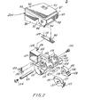
- Figs. 1-8 there is illustrated the more basic components of the work station of the present invention.
- Such components comprise two spaced legs 40 which may be in all respects identical.
- Each leg includes a lower square-in-section component 41 and an upper similar square-in-section component 42 which telescopes over the component 41.
- a rotating screw is journaled in the upper component 42 and is in mesh with a nut secured to the lower component 41. Rotation of the screw will vertically adjust the height of the leg.
- each component of the legs 41 and 42 at the top and bottom is provided with mounting holes seen at 44, by which a wide variety of arms and/or feet may be secured to the flat faces of the components at the top and bottom projecting therefrom.
- a fixed glide seen at 46 may be secured in the bottom component and a removable leg cap cover 47 is adapted to fit closely over recessed top 48.
- each leg 40 is provided with a foot 50 projecting toward the viewer and to the right, such foot being secured to the corresponding face of the bottom of the leg component 41 by suitable fasteners fitting through the screw holes 44.
- the end of the foot is provided with an adjustable glide 51.
- the foot may be covered by a foot cover 52.
- Screw ports 44 when not utilized, may be covered by screw covers 53.
- each beam is formed of a sheet metal structure and includes an outer plate 59 and an inner stiffening plate 60 which may be bent to form three horizontally extending rectangular ribs 61.
- the outer plate is inwardly folded to form a flange 62 and then folded again on itself or hemmed as indicated at 63.
- the inner plate is inwardly folded at its edges to form a short flange 64 which fits behind the folded edge 63 of the outer plate.
- the two plates of each beam may be spot welded together where contiguous.
- each beam is rounded as indicated at 66 in the same fashion as the corners of the leg components are also rounded as seen at 67.
- Secured to the upper components of the legs are vertically spaced facing U-shape brackets seen at 68.
- the bight portion of the brackets is welded to the face of the upper component of the leg as indicated at 69 and each bracket includes spaced parallel projecting legs 70 and 71.
- the face of each beam is slightly recessed as indicated at 72 to accommodate cap screws 73 which secure the beams to the brackets in the manner indicated more clearly in Figs. 1 and 8.
- each of the top two rectangular ribs 61 Secured to the interior of each of the top two rectangular ribs 61 is a horizontally extending plate in a vertical plane as seen at 76 and 77, the top and bottom horizontal and parallel edges 78 and 79 -of which form top and bottom rails, respectively.
- the plates are secured to the beams to form tracks, and the top and bottom edges thereof form rails to accommodate either for clamping or rolling movement therealong a wide variety of accessories hereinafter described.
- the top and bottom edges of the plates may be rounded, beveled, or hemmed to remove rough edges and better to accommodate the accessories. In the illustrated embodiment there is approximately a 4 cm. clearance between the two rails which permits accessories to be clamped to or mounted on both rails concurrently.
- each beam is provided with a row of horizontally elongated holes extending through both the inner and outer plates thereof, such rows being seen at 80 and 81.
- a wide variety of accessories may be mounted directly on the face of the beams to project in cantilever fashion therefrom.
- such accessories may include drawer units, filing units, back files, or hanging files, as well as specially designed cabinets for printers or disc readers, and surface supports.
- supports 83 and 84 may be secured to the upper components 42 of the legs 40 and 41 through the screw mounting holes 44 to project in cantilever fashion in the same direction as the feet 50.
- the top supports are designed to support a work top or surface 85.
- Each top support includes an underlying arm 86 and an overlying slide 87 which are hingedly interconnected at their distal or outer ends at 88. The outer end is of course the end of the support or edge of the work surface toward the user.
- the work surface 85 is relatively thin and is primarily a sheet metal structure rigidified by a honeycomb core. Its underside at each lateral edge may be provided with a T-shape channel which fits on the slides 87.
- the work surface is mounted on the slides for in and out sliding movement or towards and away from either the user or the slot 75 provided by the spaced apart beams 55 and 56.
- the surface 85 may be released for such sliding movement by a spring loaded latch seen more clearly in Fig. 2 at 90 which projects through a rectangular hole 91 in slides 87.
- the slide as seen also in Fig. 2 is provided with a slide surface 92 which is mounted on an underlying relatively shallow channel-shape frame 93 which includes, at its distal end, downwardly projecting ears 94 and 95 each of which includes holes 96.
- Such holes are adapted to be aligned with similar holes in upstanding ears 97 and 98 on the end of support arm 86. It is through such aligned holes that such arm and slide are hingedly interconnected by hinge pin 99.
- the hinge pin not only extends through the holes in the aligned ears of the arm and slide, but also through a plastic actuator housing 101.
- the actuator housing primarily provides a mounting for pivoting paddle 102 for releasing catch 90 as well as sawtooth motor switch 103 controlling, for example, the motorized adjustment of the height of the leg or legs.
- the actuator or plastic switch housing 101 is a one-piece molded plastic part which includes a central web 105 which at its inner end has a laterally projecting ear 106 and an inverted L-shape wire shield 107.
- the ear includes a hole 108 adapted to align with hole 109 in spring 110 of spring catch 90. Both such holes are adapted to fit over a projecting stud on the under surface of the slide 87 and may be held thereto by a suitable fastener with the spring catch 90 then projecting through the hole 91.
- Each block includes near its inner end slots as seen at 114 and 115 which are separated by upstanding outer and inner ears 116 and 117, each outer ear having hole 118 while each inner ear has upwardly opening slot 119.
- Such holes and slots are aligned and also aligned with a corresponding slot 120 in the web 105.
- the ears ll7 with the slots 119 therein are spaced from the web and connected thereto by a bridge along the bottom providing slots or recesses 122 and 123 which accommodate lever 102 and the saw tooth motor switch 103, respectively.
- Extending circularly upwardly from the bridge are tabs 124 and 125 which fit through slots 126 and 127 on the projecting tab portion 128 of lever 102 and the saw tooth projecting portion of the switch actuator 103, respectively.
- the slots 114 and ll5 of the actuator housing 101 accommodate the contiguous ears 94, 97, and 95, 98 on the slide and arm, respectively.
- a three-position switch 129 is secured to one wall of the web as indicated and its toggle arm 130 meshes with slot 131 on the inner end of the switch actuator 103 when in assembled condition.
- the actuator housing is secured to the underside of the slide 87 and of course pivots therewith.
- the projecting end of the semicircular blocks 112 and 113 provide on their generally diametral surface indicated at 132 clearance for the edge of the work surface 85 to slide thereover when released by the spring catch 90.
- the hinge pin 99 held by cap screws 134 and 135 at each end, with the heads being large enough to be caught by the ears 116, will pass through the following elements in succession, reading from left to right in Fig. 2; the lefthand ear 116 and its hole ll8; ear 94; ear 97; the slot 119 of ear 117; hole 137 in motor switch actuator 103; slot 120; hole 138 in lever 102; slot 119 in ear 117; ear 98; ear 95; and the hole 118 in righthand ear 116.
- the switch actuator assembly may provide at the distal end of the arm or the edge of the work surface closest to the user controls both for the height adjustment of the legs and thus all of the components supported thereby as well as for release of the work surface 85 for in and out sliding movement along the slides 87.
- the actuator assembly presents at a position convenient to the user at least two switches or actuators at each edge of the work surface 85. It will of course occur to one skilled in the art that such convenience switches or levers provided through the actuator housing may be for a variety of purposes including concurrent vertical adjustment of both legs, individual adjustment of each leg, or adjustment of angle of the work surface or even selected accessories.
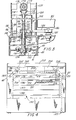
- Fig. 3 there is illustrated in section the upper end of a leg illustrating the manner in which the leg may be driven for motorized vertical adjustment or by use of a hand tool.
- Fig. 3 illustrates components of the present invention which may not normally be used together.
- the top 48 includes a horizontal wall 140 and a downwardly projecting recessed interior flange 141 which fits inside the tubular component 42 of the leg.
- Top 140 has a projecting shoulder 142 which seats on top of the tubular component 42 of the leg 40.
- a hole 143 Centered in the horizontal wall 140 is a hole 143 through which extends a plastic sleeve bearing 144.
- the plastic sleeve bearing 144 accommodates reduced diameter cylindrical portion 145 of height adjusting screw 146.
- a roller thrust bearing 147 extends between the shoulder at the top of the screw portion and the underside of the plastic bearing.
- a bottom wall 149 of a chair-bracket 150 is provided with a hole through which the bearing 144 extends, such bearing being secured by washer 152 to be held in place by the illustrated snap ring.
- the screw 146 projects through a nut 154 captured between the parallel side walls 155 of nut retainer 156.
- the nut is vertically captured by top strap 157 and both the strap and nut retainer are held to horizontal plate 159 secured to the interior of the leg component 41 by the fasteners indicated at 160. In this manner rotation of the screw in opposite directions will cause the upper component 42 of the leg to move up and down.
- the upper end of the screw 146 is provided with a yet further reduced diameter extension 162 to which is secured a bushing by transverse pin 164.
- the lower end of the bushing has a cylindrical hole accommodating the extension 162 while the upper end of the bushing is provided with a hexagonal hole 165.
- the hexagonal hole accommodates hexagonal pin 166 which may be roll pin connected at 167 to extension shaft 168.
- the extension shaft extends through a flanged bushing 170 mounted in horizontal plate 171 of the chair bracket and a miter gear 172 is mounted on top of the extension shaft.
- miter gear is in mesh with a further miter gear 173 mounted on horizontal cross shaft 174 which extends between the projecting horizontal components 175 mounted on the side walls 176 of the chair bracket.
- the cross shaft is provided with a bushing on its end having hexagonal opening 178.
- the hexagonal opening will be positioned adjacent a hole in the wall facing the viewer of leg extension 180 in which the chair bracket 150 snugly fits.
- the leg extension has the same or similar configuration to the lower component 41 of the telescoping legs and provides a vertical leg extension when the cap 47 is removed and replaced by such leg extension.
- the leg extension like the cap, fits on upwardly facing shoulder 181 on the top 48 with upwardly extending flange 182 telescoping therewithin.
- the pin 164 in addition to securing the bushing 163 to the top of the screw, may also serve to secure timing belt pulley 184 to the bushing and also to the screw.
- a timing belt 185 connects the pulley 184 to the pulley 186 mounted on shaft 187 extending parallel to the screw and journaled on bracket 189 which may be secured to the beam or leg. Suitable slots are provided in the leg top and/or chair bracket to accommodate the timing belt 185.
- the screw may be motor driven through suitable transmissions and one or more motors as hereinafter described, all below the level of the work surface.
- Fig. 3 it should be appreciated that not all of the components seen in Fig. 3 may necessarily be used together.
- the chair bracket, leg extension 180 as well as the extension shaft and the gears 172 and 173 may not necessarily be employed.
- the top of the screw would be provided with the bushing 163 with the hexagonal hole 165 being exposed upon removal of the cap 47.
- manual adjustment of the screw is obtained by simply inserting a hexagonal tool in the hexagonal hole 165, such tool being, for example, an Allen wrench.
- the hexagonal tool would be inserted through the hole in the facing wall thereof.
- the motor drive is optional and the pulleys and timing belt may be employed only in the event such motor drive is utilized, or in the event of single source manual adjustment. Even with the motor drive, manual adjustment may still be made with a suitable hexagonal tool placed in the top bushing 163. It will also be appreciated that the projecting end of the shaft 187 may be provided with a hexagonal recess also to receive an adjustment tool.
- a work station assembled.
- the wiring tray comprises a series of transverse fairly large channels seen at 196, 197 and 198.
- Such channels are open at their ends and communicate with horizontal slot or opening 200 which is perhaps seen more clearly in Fig. 2.
- the slot 200 extends between the arm and the overlying slide and permits lateral access through the arm from the wiring tray to lateral extensions or components.
- the rearmost channel 196 may be provided with a convenience outlet seen at 201.
- the convenience outlet may be prewired for light, power, communications or interfaces for the various components of computers such as the keyboard, screen, disc reader or printer.
- a two motor drive seen schematically at 203 and 204.
- Each motor includes a transmission seen at 205 and 206, respectively, driving the shaft 187 on which is situated the pulley 186.
- Such shafts at each side of the table or work station may be interconnected through miter gearing shown at 207 and 208 and line shaft 209. With the line shaft the screws in each leg would rotate in synchronism.
- a single switch 103 may control both motors. It will be appreciated that leveling can be accomplished by utilizing the adjustable glide 51. It will also be appreciated that with the line shaft a single somewhat more powerful motor may be employed for vertical adjustment of both legs.
- suitable limit switches seen at 211 in each leg or on the outside of each leg will not permit rotation of the motor in a given direction beyond set limits.
- the motor and transmission may be provided in a housing indicated at 212 which extends to the rear of the beam and may be fastened to the legs.
- a housing has the appearance of a short work surface and may be constructed with a pivoting slide so that the top surface may be pivoted upwardly or slid rearwardly to expose the motor, transmission and shafts.
- Such housing with or without the motors and transmissions is seen in end elevation in Figs. 27, 28 and 37, for example.
- the back edge of the tray as indicated at 214 and 215 may be provided with one or more wire managers which are simply plastic clips holding wires separated.
- the wires may extend downwardly over the rear edge of the tray indicated at 216 or they may extend over the top of the beams beneath a wire and pulley cover seen at 217.
- wiring to the convenience outlet may be provided through tubular wire manager 220 which may extend upwardly on the interior of each leg.
- Below the wire manager coil cord indicated at 221 may be provided with the cord extending through wire clip 222.
- Coil cord indicated at 223 may be provided from the convenience outlet to the video support as well as to other accessories such as task lights or telephone pads. It will also be appreciated that the coil cord 221 may be encased in a similar wire manager secured to the lower telescoping leg component 41 and telescoping with the wire manager 220.
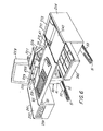
- Fig. 6 there is illustrated a more fully assembled work station showing the work surface 85 in front and the somewhat shorter housing 212 at the back of the work station with the open slot 75 therebetween. It is noted that the caps 47 at the tops of the legs 40 are flush with both surfaces. Projecting upwardly through the slot are certain accessories such as video screen support 225, a phone pad 226 and one form of task light 227.
- the video screen support supports video screen 228. In the illustrated form, the video screen support may be power operated up and down by the lever 229 and the angle of the video screen support may be adjusted by knob 230.
- the work surface 85 supports a keyboard indicated at 231.
- cabinets 233 and 234 Supported at each side of the work surface 85 and housing 212 are cabinets 233 and 234. Such cabinets may be secured to the outside of the upper components of the leg 40 and also to the projecting arms supporting both the work surface 85 as well as the housing 212.
- the cabinet 233 may contain a built-in disc reader 236 at its front while the cabinet 234 includes an opening 237 in which is mounted a printer 238.
- the front of the cabinet 234 may also include one or more drawers indicated at 240.
- the cabinet 233 includes a top surface 241 which constitutes an extension of the. work surface 85.
- the cabinet 234 also includes a surface 242 which is at the same plane as the surfaces 85 and 241.
- Height adjustment if the work station is motor driven, may be obtained through the actuator housing 101 and the appropriate saw tooth motor switch or switches. The entire work surface as well as the attached cabinets 233 and 234 will move up or down upon command. Other options for work surface height adjustment include single point synchronized manual adjustment; individual leg adjustment; and individual adjustment when necessitated by upper support leg 180, also performed by inserting a hex tool in socket 178. It will be appreciated that the accessories illustrated may be positioned at any desired location along the slot 75 in the manner hereinafter described.
- a video screen support which includes a carriage shown generally at 250 which includes primarily a flanged vertical plate 251 with stud mounted V-shape rollers 252 mounted at each corner thereof.
- the studs of the lower two rollers are threaded and extend through vertically elongated holes 253 so that the lower rollers may be moved slightly up and down when nut 254 on the side of the plate 251 opposite the rollers is loosened.
- the carriage 250 may be mounted on the vertical rail edges 78 and 79 of the plate or track 77 of the beam 56.
- the top and bottom flanges 256 of the carriage plate assist in securing to the plate a vertical tubular column 257.
- the tubular column projects somewhat above and below the plate and includes at its lower end a fitting 258, to the interior of which is secured a somewhat smaller upwardly projecting interior column 259, on top of which secured against rotation is a shouldered nut 260.
- the inner and outer columns as well as the nut 260 are vertically fixed.
- a screw 261 Extending downwardly through the nut is a screw 261.
- the upper end of the screw is provided with a fitting 262 securing the screw for rotation with shaft 263 which is mounted in sleeve bearing 264 and ball bearing 265 inside vertically movable tubular column 266.
- the lower end of the tubular column 266 is provided with a sliding bearing 267 fitting within the column 257.
- Such column 257 at its upper end also is provided with a fixed bearing 268 in which the vertically movable column 266 slides.
- the column 266 is thus designed to move not only up and down but also to pivot about its vertical axis.
- a hollow gooseneck or offset 270 which includes on its distal end a tubular post 271, the axis of which is parallel to the axis of the column 266.
- tubular column 272 which is part of the video terminal support tray shown generally at 273.
- the column 272 is in the center of a transverse bridge member 275 interconnecting the sides 277 and 278 of a generally rectangular frame through pivots 279 and 280, respectively.
- the front of the frame is provided with an upstanding face plate 282 on which manual adjustment knobs 283 and 284 are mounted.
- Such adjustment knobs may be provided with diametral slots at one end of which is pivotally mounted a crank handle. In a recessed position the crank handle is flush with the knob. In an operative position it is pivoted 180° and may be employed to rotate the knob.
- the side frame members 278 and 279 are provided with slightly projecting top flanges 286 and 287, respectively, to which are adjustably secured transverse video screen support members 290 and 291.
- Each of the transverse support members may be adjusted fore and aft of the frame or in the direction of the arrows 292 in Fig. ll by loosening and then tightening fasteners 294 which are threaded in sleeve nuts 295 secured to the transverse support members.
- Each fastener includes a clamp washer 296 underlying the flanges 286 and 287.
- the transverse support members may be provided with a series of slotted holes indicated at 298 through which the transverse support members may secure a video terminal. With the slotted holes and the fore and aft adjustment, substantially any video terminal may be supported securely from the tray.
- the knob 283 seen in Fig. 11 is secured to a shaft 300 mounted in the face plate 282 against axial movement but for rotation as indicated at 301.
- the shaft on its end interior of the face plate is threaded as indicated at 302, such threaded shaft being received in blind threaded hole 303 of rod 304.
- the opposite end of the rod is pivoted at 305 to the bridge 275 significantly above its pivot point to the frame as seen more clearly in Fig. 10.
- rotation of the knob 283 will cause the video terminal tray to pivot about the horizontal axis of the pivots 279 and 280. In this manner the horizontal tilt of the tray may be controlled.
- the other knob 284 is connected to shaft 307 which is journaled not only in the face plate as indicated at 308, but also in hub 309 secured to the interior of the side frame 278.
- the inner projecting end of the shaft 307 has secured thereto an end fitting 310 of flexible shaft 311 which extends downwardly through the column 271 of the gooseneck 270.
- the opposite end of the flexible shaft 311 is secured by similar fitting 312 to the top of shaft 263 seen in Fig. 10. In this manner, rotation of the knob 284 will cause the screw 261 to turn raising or lowering the tray 273 with respect to the mounting carriage 250.
- the mounting tray for the video terminal may be moved horizontally along the track 77 by means of the roller carriage. It may also be moved up and down by manual rotation of the knob 284. It may also be moved about the vertical axis of the column 266 by the amount of the throw of the gooseneck 270 whether this be to the side or fore and aft. It may also be pivoted about the vertical axis of the column 271. Its horizontal tilt or inclination may also be adjusted by knob 283 about the horizontal axis of pivots 279 and 280. Of course, the entire unit moves with the adjustment of the legs 40.
- the height adjustment may be powered or motor controlled.
- a motor 315 operative to rotate the screw 316 which is vertically fixed.
- the screw extends through a nut 317 mounted on the lower end of vertically movable column 318.
- the upstanding screw 316 is journaled at 320 at the lower end of the fixed column driven by motor 315 through timing belt 321 transmission extending between motor pulley 322 and screw pulley 323.
- the motor as well as the pulleys are mounted on plate 324 extending from the somewhat elongated plate of the carriage.
- a limit switch mechanism indicated at 325 may be provided to indicate the limits of vertical motor driven adjustment.
- a capacitor unit 326 for the motor 315 may be provided mounted on the plate of the carriage.
- the height adjustment of the video terminal tray may be motor driven rather than manually driven as indicated by the embodiment of Fig. 12. Again, the carriage of the motor driven height adjustment for the video terminal may be mounted on the tracks of the beam in the same manner. Control of the motor driven height adjustment may be as indicated in Fig. 6.
- Mounting post 330 comprises a vertically extending base plate 331 which includes at its bottom a rearwardly extending flange 332 and at its top a forwardly extending inverted V-shape flange 333.
- the lower rear surface of the flange 332 is provided with a piano hinge 334 which pivotally secures hinge plate 335 to the bottom of the mounting post.
- the forward edge of the hinge plate 335 is provided with an upwardly opening V-shape configuration seen at 336.
- the V-shape configurations 333 and 336 are designed to clamp the top and bottom rails of the rail plate of either beam as indicated at 77.
- a channel Secured to the back of the plate 331 is a channel from the upper end of which projects tubular post 339.
- the post, channel and plate may be welded together.
- the top of the post 339 is provided with a tab 340 designed to mate with a forked extension on an interfitting part or a washer tab.
- a pivot bracket 342 to which is pivoted a lever 343.
- the lever may move from the full line position seen in Fig. 14 to the phantom line position indicated at 344 and includes a stop projection 345 which limits the clockwise movement of the lever to such phantom line position.
- the phantom line position is the unlocked position while the full line position is the locked position.
- Pivoted to the lever at 347 is a pivot link plate 348 to which is secured rod 349.
- the rod 349 extends through a hole in flange 332 and is provided with a transverse roll pin 350 between the flange 332 and the plate 335.
- the rod extends through a hole in the hinge plate 335 and below the hinge plate there is a tapered spacer 351 held in position by lock nuts 352.
- the pivot 347 is slightly over center of the pivot 353 for the lever 343 in the toggle locked position of the lever. In such position the mounting post will be firmly clamped to the rail 77. When the lever is swung to its open or phantom line position 344, the mounting post may be released.
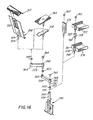
- Fig. 16 there are illustrated some variations in accessories which may be supported through the mounting post. Reading upwardly from the top of the post it will be seen that there is provided a stop washer 355.
- the stop washer has a downwardly projecting tab 356 and an upwardly projecting tab 357, such tabs being spaced 90° apart.
- the downwardly projecting tab is designed to engage the tab 340 on top of the mounting post while the upwardly projecting tab may engage swing arm 359.
- the swing arm at its proximal end is provided with a two-part tubular pintle 360 which includes a downwardly projecting smaller diameter tube 361 designed to fit closely within the top of the post 339.
- the upper end of the pintle is the same diameter as the post and includes a socket 362 which is the same internal diameter as the post. When not in use, the socket may be closed by a trim cap 363.
- the outer end of the swing arm is provided with a tubular socket 364 which has the same internal diameter as the socket 362 and of course the post 339.
- each of the accessories may be positioned in the socket of the second swing arm, such illustrated accessories being a copy reader 368, or either of phone holder pads 369 or 370.
- the copy reader 368 may be provided with an optional plug-in light at its top indicated at 371. It may also have a spring ratchet height adjustment as seen at 372.
- each of the accessories is provided with a two-part post seen generally at 373 with the lower portion being of reduced diameter indicated at 374 and again designed closely to fit within the sockets 364, 362, or, for that matter, directly into the top of the mounting post.
- the larger diameter portion of the post also provides a shoulder limiting the extent of insertion of the smaller diameter portion to the vertical extent of the swing arm sockets.
- Fig. 16 there is illustrated another type of phone holder 375 and perforated metal letter trays 376 and 377, which have secured thereto the two-part or two diameter tubular post as seen at 378.
- the lower or smaller diameter portion fits within the appropriate socket while the upper or larger diameter portion forms a socket which when not in use may be closed by the trim cap seen at 363.
- a spacer 379 Positioned between the two letter trays is a spacer 379.
- the spacer is simply the same configuration as the post but is not secured to an accessory.
- the height of the upper or larger diameter portion of the spacer may vary.
- the lower or smaller diameter portion is designed to fit in the open socket at the top of the post of the letter tray 376. It will be appreciated that more than one letter tray may be stacked in the manner indicated.
- the lower end of the larger diameter of the post 378 may be provided with a downwardly projecting two-prong fork 380 with the tines being designed to fit one on each side of the tab 340 at the top of the post.
- Tabs similar to the tab 340 may be provided at the top of the post 378 as indicated at 381 as well as at the top of the spacer 379.
- the spacer may also be provided with a fork indicated at 382 and also a tab indicated at 383, the tab cooperating with the fork on the post of letter tray 377.
- the fork 382 on the spacer of course cooperates with the tab 381 on the post 378. In this manner the letter trays may be mounted on the top of the post 339 and held against rotation.
- any of the accessories illustrated may be mounted on any desirable open socket, whether it be the top of the post 339, the socket 362 at the inner end of the swing arm, or the socket 364 at the outer end. With the employment of two swing arms, the position of the accessory can manually be adjusted over a wide area for the convenience of the vision and reach of the user. It will also be appreciated that spacer columns like those illustrated, with or without anti-rotation devices, may be inserted where desired to obtain the desired height adjustment.
- the letter tray includes a perforated one piece side wall and floor 385 secured to folded edge bulkhead 386. The edges of the walls and floor may be covered by a plastic bead seen at 387.
- a two-part post 388 Secured to the bulkhead is a two-part post 388 which may be the same as the posts illustrated mounted on the letter trays in Fig. 16.
- the post includes a lower smaller diameter portion 389 which is adapted to plug into the top of spacer 379.
- the tubular post is provided with a top tab 390 and a lower projecting fork 391, the latter cooperating with the tab 383 on the spacer 379.
- the top of the post 388 may be closed by a trim cap, if not further used.
- the mounting post assembly may also support task lamps with the wiring for the lamps extending through the posts, the spacer and through the tubular post 339 to a transformer which may be conveniently mounted on the bottom of the mounting post assembly 330.
- Wiring for the task light 371 on top of the copy reader may also extend through the posts, swing arms, etc. to its convenient transformer mounted on the plate of the mounting post assembly 330.
- Such task light shown generally at 400 includes a carriage plate 401 having a top flange 402.
- Top V-shape rollers 403 and 404 are mounted on the front of the plate at the upper corners.
- Rollers 405 and 406 at the lower corners of the plate are mounted on levers 407 and 408, pivoted at 409 and 410, respectively.
- the inner ends of each lever are provided with pins seen at 412 and 413 which are captured in slightly horizontally elongated slots 414 and 415 in the lower end of lever arm 416.
- the lever arm is mounted for vertical movement on the front of the plate 401 and is held in position by alignment tabs 417. Above the alignment tabs 417 the lever arm is adapted to spring from the plane of the plate as indicated at 418. As the lever arm projects through an appropriate notch in the top flange 402, it becomes more narrow as indicated at 419 and on each side of the more narrow portion there are provided projecting locking tabs 420 and 421 designed to cooperate with the underside of the flange in a locking position but to be released therefrom if the lever arm is sprung from its locking position or to the right above the alignment tabs as seen in Fig. 19. This then releases the lever arm for vertical upward movement.
- the bottom corners of the plate 401 are cut away as indicated at 425 and 426 and a bottom flange to the plate is provided at 427. To this plate there is secured a transformer 428.
- the tubes may be secured to the back plate as by welding.
- the top of the tubes are interconnected by a connector 434 which also provides a mounting for a fixed horizontally projecting inner tube 435.
- the opposite end of the connector is closed with a removable plastic cap 436.
- Mounted for telescoping movement over the inner tube 435 is an outer tube 437.
- the two tubes may have suitable plastic bearings interposed therebetween permitting the light fixture shown generally at 438 secured to the outer tube to move to the right and left as seen in Fig.
- the inner tube 437 is provided with a knob 440 for operating rotary on-off switch 441.
- the fixture includes a generally semi-cylindrical reflector 443 as well as a socket 444 for light bulbs 445.
- a U-shape rod 446 with the U-shape bight portion projecting beyond the reflector as indicated at 447 to provide a convenient handle for both telescoping positional adjustment as well as tilting adjustment.
- the inside of the tube 435 provides a chamber and a coil cord may extend from wiring passage 448 communicating the top of the tubes 430 and 431 with the wire chamber to the rotary switch 441.
- roller carriages there has been illustrated two types of roller carriages and one type of clamp carriage, all to be mounted on the tracks or rails on the spaced beams. It will also be appreciated that such carriages or supports on the track are interchangeable. In any event, the accessories employed and their means of mounting on the track may vary widely.
- FIG. 20 there is illustrated one form of space planning alternative utilizing visual and acoustical screens 450 which may be of the type shown in applicant's copending application entitled "Screen System for Offices and Method of Making and Installing Same", filed even date herewith.
- the system shown in Fig. 20 may comprise essentially two similar work stations back to back indicated generally at 452 and 453.
- the work stations are generally similar and are only separated by screen panel 454.
- Each work station comprises a work station supported on three separate legs 455, 456 and 457. However, for the third leg 457, only the leg cap 47 is visible.
- Each of the legs 455 and 456 may be provided with a vertical extension 180 which is described in detail in Fig. 3. As indicated, such extensions are provided with an aperture indicated at 458 by which the height adjustment of the legs may be obtained.
- the leg extensions support high storage components seen at 460.
- Each of the legs is interconnected by the spaced structural beams to provide a quite rigid triangular structure and the opposite legs 455 and 457 may be provided with inwardly directed feet seen at 462.
- each station includes a major work surface 464 supported on arms 465 and 466.
- the arm 465 is supported from the leg 455 while the arm 466 is supported from the face of the beam.
- Another lateral major work surface indicated at 468 is supported on arms extending from the beam interconnecting the leg 456 and the leg not shown, as well as an arm projecting from the leg not shown.
- a work surface 469 which may neither slide nor tilt, but which is readily removable.
- the work surface 469 is supported from the adjacent beams and arms.
- a wiring channel may extend beneath such surface 469 interconnecting the wiring trays beneath the surfaces 464 and 468 through suitable channels and through the slots 200 in such arms.
- a typical electronic work station layout which in reality comprises three separate work stations 471, 472 and 473, the middle work station including triangular extension wings 474 and 475.
- Each work station is height adjustable by means of the two legs 40, readily identifiable.
- Work station 471 may include a printer support surface 478 supporting printer 479.
- To the rear of the legs there is provided a support surface for, for example, wire paper retrieval baskets 480.
- the work station 472 includes a major work surface 85 supporting a keyboard or the like 231 and a video terminal 228 supported on a suitable support extending from the open slot 75.
- the work station 472 is height adjustable and the triangular sections 474 and 475 move with the work surface 85 when height adjusted.
- the triangular extensions will be provided with subjacent wiring channels permitting the wiring trays of each of the work stations to be interconnected beneath the surface.
- the work station 473 may comprise a larger work surface 85 with one or more accessories supported through the slot 75 such as the indicated track mounted task lamp.
- other or additional accessories may be provided at each work station, each being mounted on the beam tracks in the manner previously described.
- FIG. 22-38 it will be seen that there is illustrated an eye position 490 for the user in each of Figs. 22-30, such eye positions having been developed from ergonomic studies. From the arrangement seen in Fig. 22 it will be seen that the screen 491 of the video terminal 492 supported on the tray 273 is positioned at the same eye distance as copy reader 368 and keyboard 231 supported on the work surface 85.
- Fig. 23 for larger video units 493, they may be supported on low adjustable video supports 494 hung over the back of the rear beam.
- the keyboard 231 may be supported on a relatively short tilt top seen at 495.
- Fig. 24 there is shown a work station for an integrated video monitor, that is one in which the video monitor 497 and keyboard 498 are part of one unit.
- the copy holder 368 may be positioned at the same distance as the screen of the video unit.
- Fig. 25 there is illustrated a standard desk arrangement wherein the screen of the video monitor 500 may be positioned at the approximate angle and distance as the keyboard 231.
- Fig. 26 there is illustrated a desk which may be provided with a recessed or lower front surface 502 supporting keyboard 231 with the video monitor 503 mounted on disc unit 504.
- Fig. 27 there is illustrated an arrangement similar to Fig. 22 but with the video monitor 492 at its lowermost position. Again the video screen, copy holder and keyboard are at the same eye distance from the user.
Landscapes
- Devices For Indicating Variable Information By Combining Individual Elements (AREA)
- Illuminated Signs And Luminous Advertising (AREA)
- Bearings For Parts Moving Linearly (AREA)
- Spinning Or Twisting Of Yarns (AREA)
- Forklifts And Lifting Vehicles (AREA)
- Workshop Equipment, Work Benches, Supports, Or Storage Means (AREA)
- Tables And Desks Characterized By Structural Shape (AREA)
Applications Claiming Priority (2)
| Application Number | Priority Date | Filing Date | Title |
|---|---|---|---|
| US55815983A | 1983-12-05 | 1983-12-05 | |
| US558159 | 1983-12-05 |
Publications (2)
| Publication Number | Publication Date |
|---|---|
| EP0145410A2 true EP0145410A2 (de) | 1985-06-19 |
| EP0145410A3 EP0145410A3 (de) | 1987-05-13 |
Family
ID=24228447
Family Applications (1)
| Application Number | Title | Priority Date | Filing Date |
|---|---|---|---|
| EP84308242A Withdrawn EP0145410A3 (de) | 1983-12-05 | 1984-11-28 | Verstellbarer Arbeitsbereich und Zubehör dafür |
Country Status (7)
| Country | Link |
|---|---|
| EP (1) | EP0145410A3 (de) |
| JP (1) | JPS60156408A (de) |
| KR (1) | KR850004200A (de) |
| AU (1) | AU3607384A (de) |
| DK (1) | DK575084A (de) |
| FI (1) | FI844794L (de) |
| NO (1) | NO844839L (de) |
Cited By (45)
| Publication number | Priority date | Publication date | Assignee | Title |
|---|---|---|---|---|
| DE3606624A1 (de) * | 1986-02-28 | 1987-11-05 | Hartmut S Engel | Arbeitstisch |
| EP0283016A1 (de) * | 1987-03-18 | 1988-09-21 | Herman Miller, Inc. | Arbeitsfläche für integrierte EDV-Geräte |
| EP0382514A2 (de) * | 1989-02-07 | 1990-08-16 | Steelcase Inc. | Möbelbausatz |
| WO1990013239A1 (en) * | 1989-05-12 | 1990-11-15 | Haworth, Ltd. | Desk system |
| GB2197189B (en) * | 1986-11-14 | 1991-07-10 | Nova Link Limited | Beam-type work station system |
| EP0278291B1 (de) * | 1987-01-22 | 1992-09-09 | Hartmut S. Engel | Arbeitstisch |
| US5199773A (en) * | 1990-12-20 | 1993-04-06 | Engineered Data Products, Inc. | Desk type work station |
| USRE34266E (en) * | 1984-02-16 | 1993-06-01 | Work station with underdesk display | |
| US5265952A (en) * | 1992-03-27 | 1993-11-30 | Fisher Controls International, Inc. | Operator work station |
| US5321579A (en) * | 1991-07-19 | 1994-06-14 | Teknion Furniture Systems | Office panelling system with a monitor screen mounted on a cantilevered adjustable arm |
| US5352033A (en) * | 1992-03-27 | 1994-10-04 | Fisher-Rosemount Systems, Inc. | Operator work station having a monitor support assembly |
| WO1995030357A1 (en) * | 1994-05-06 | 1995-11-16 | Ergonomi Design A/S | Computer desk |
| US5483903A (en) * | 1994-06-10 | 1996-01-16 | Haworth, Inc. | Table |
| EP0791311A1 (de) * | 1996-02-15 | 1997-08-27 | Inter Company Computer, Engineering, Design Services, in het kort : " Concept Design", naamloze vennootschap | Freistehendes modulares Möbel |
| CH688607A5 (de) * | 1995-02-07 | 1997-12-15 | Langhans & Schondelmaier Ag | Arbeitstisch mit mindestens zwei Ebenen. |
| US5746488A (en) * | 1994-02-01 | 1998-05-05 | Lacour,Inc. | Stressed modular desk system |
| GB2326089A (en) * | 1997-06-09 | 1998-12-16 | Nova Link Limited | Beam type workstation |
| GB2327039A (en) * | 1997-07-09 | 1999-01-13 | Lg Electronics Inc | Adjustable support structure for video appliance |
| US5975657A (en) * | 1994-02-01 | 1999-11-02 | Lacour Incorporated | Flexible desk system |
| WO1999060889A2 (en) * | 1998-05-28 | 1999-12-02 | Herman Miller, Inc. | Desk system |
| US6033045A (en) * | 1995-04-19 | 2000-03-07 | Fay D. Roberts | Trapezoidal hidden-monitor computer desk modules and assemblies thereof |
| US6050659A (en) * | 1998-01-30 | 2000-04-18 | Lacour Incorporated | Frame-type desk system |
| US6152048A (en) * | 1996-06-04 | 2000-11-28 | Nova-Link Limited | Beam-type office furniture system and modules |
| US6202567B1 (en) * | 1994-06-10 | 2001-03-20 | Krueger International, Inc. | Modular table system with cable management |
| US6315308B1 (en) * | 2000-05-15 | 2001-11-13 | Miles Anthony Konopka | Mobile data/audio/video/interactive presentation cart |
| FR2813510A1 (fr) * | 2000-09-06 | 2002-03-08 | Philippe Pierre Franc Lassalle | Meuble informatique a plateaux reglables par commande electrique unique |
| US6721178B1 (en) | 1998-09-18 | 2004-04-13 | Fhs Acquisition, Llc | Mobile clinical workstation |
| US7066097B2 (en) | 2002-02-01 | 2006-06-27 | Krueger International, Inc. | Worksurface support system with power and communication capability and front and rear access covers |
| US7143552B2 (en) | 2002-08-26 | 2006-12-05 | Nova-Link Limited | Supporting spine structure for modular office furniture |
| GB2431570A (en) * | 2005-10-13 | 2007-05-02 | Specialist Joinery Fittings Lt | Modular furniture system with service conduit |
| US7612999B2 (en) | 1998-09-18 | 2009-11-03 | Flo Healthcare Solutions, Llc | Mobile clinical workstation |
| EP2280624A2 (de) * | 2008-05-28 | 2011-02-09 | Steelcase Inc. | Arbeitsflächenanordnung |
| US8180485B2 (en) | 2006-02-11 | 2012-05-15 | Omnicell, Inc. | Medication dispensing cart |
| US8378620B2 (en) | 2006-08-21 | 2013-02-19 | Omnicell, Inc. | Solar charged mobile working stations |
| US8534752B2 (en) | 2010-06-02 | 2013-09-17 | Steelcase Inc. | Reconfigurable table assemblies |
| US8667908B2 (en) | 2010-06-02 | 2014-03-11 | Steelcase Inc. | Frame type table assemblies |
| US8773270B2 (en) | 2010-12-06 | 2014-07-08 | Omnicell, Inc. | Computer controlled and monitored medical storage system |
| US8794579B2 (en) | 2005-06-03 | 2014-08-05 | Steelcase, Inc. | Support arm assembly |
| US9164537B2 (en) | 2013-03-15 | 2015-10-20 | Toshiba Global Commerce Solutions Holding Corporation | Display screen assembly having a selectively engageable mount assembly |
| US9185974B2 (en) | 2010-06-02 | 2015-11-17 | Steelcase Inc. | Frame type workstation configurations |
| US9210999B2 (en) | 2010-06-02 | 2015-12-15 | Steelcase Inc. | Frame type table assemblies |
| US10039374B2 (en) | 2016-05-13 | 2018-08-07 | Steelcase Inc. | Multi-tiered workstation assembly |
| US10517392B2 (en) | 2016-05-13 | 2019-12-31 | Steelcase Inc. | Multi-tiered workstation assembly |
| CN112956441A (zh) * | 2021-03-03 | 2021-06-15 | 广东香良水产有限公司 | 一种工厂化养鱼饲料同步投放装置及其投放方法 |
| US11109672B2 (en) | 2018-11-20 | 2021-09-07 | Squaregrove, LLC | Vertically adjustable desk with under-carriage mounting system |
Families Citing this family (5)
| Publication number | Priority date | Publication date | Assignee | Title |
|---|---|---|---|---|
| AU581818B2 (en) * | 1986-05-26 | 1989-03-02 | Richard Howard | A computer workstation |
| AU598309B2 (en) * | 1986-10-23 | 1990-06-21 | Trenton Pty Ltd | Work station |
| JP2699290B2 (ja) * | 1991-11-14 | 1998-01-19 | 株式会社 イトーキ | システムデスク用のコア部材 |
| DE29516695U1 (de) * | 1995-10-23 | 1996-02-01 | Klugkist Gmbh Bueromoebel Fuer | System zur Erstellung von Büro- und/oder Arbeitsumgebungen |
| US7677182B2 (en) | 2004-05-27 | 2010-03-16 | Steelcase Development Corporation | Two person work environment |
Citations (3)
| Publication number | Priority date | Publication date | Assignee | Title |
|---|---|---|---|---|
| FR2373103A1 (fr) * | 1976-12-06 | 1978-06-30 | Naess Ture | Pupitre de terminal de donnees |
| FR2516769A1 (fr) * | 1981-11-20 | 1983-05-27 | Koenig & Neurath Kg | Table de travail equipee d'une tablette annexe pivotante |
| FR2523828A1 (fr) * | 1982-03-26 | 1983-09-30 | Rochebrune | Mobilier de bureau adapte pour recevoir notamment du materiel informatique |
-
1984
- 1984-11-28 EP EP84308242A patent/EP0145410A3/de not_active Withdrawn
- 1984-11-30 AU AU36073/84A patent/AU3607384A/en not_active Abandoned
- 1984-12-04 DK DK575084A patent/DK575084A/da unknown
- 1984-12-04 NO NO844839A patent/NO844839L/no unknown
- 1984-12-05 JP JP59255823A patent/JPS60156408A/ja active Pending
- 1984-12-05 FI FI844794A patent/FI844794L/fi not_active Application Discontinuation
- 1984-12-05 KR KR1019840007666A patent/KR850004200A/ko not_active Application Discontinuation
Patent Citations (3)
| Publication number | Priority date | Publication date | Assignee | Title |
|---|---|---|---|---|
| FR2373103A1 (fr) * | 1976-12-06 | 1978-06-30 | Naess Ture | Pupitre de terminal de donnees |
| FR2516769A1 (fr) * | 1981-11-20 | 1983-05-27 | Koenig & Neurath Kg | Table de travail equipee d'une tablette annexe pivotante |
| FR2523828A1 (fr) * | 1982-03-26 | 1983-09-30 | Rochebrune | Mobilier de bureau adapte pour recevoir notamment du materiel informatique |
Cited By (73)
| Publication number | Priority date | Publication date | Assignee | Title |
|---|---|---|---|---|
| USRE34266E (en) * | 1984-02-16 | 1993-06-01 | Work station with underdesk display | |
| DE3606624A1 (de) * | 1986-02-28 | 1987-11-05 | Hartmut S Engel | Arbeitstisch |
| GB2197189B (en) * | 1986-11-14 | 1991-07-10 | Nova Link Limited | Beam-type work station system |
| EP0278291B1 (de) * | 1987-01-22 | 1992-09-09 | Hartmut S. Engel | Arbeitstisch |
| EP0283016A1 (de) * | 1987-03-18 | 1988-09-21 | Herman Miller, Inc. | Arbeitsfläche für integrierte EDV-Geräte |
| US4852500A (en) * | 1987-03-18 | 1989-08-01 | Herman Miller, Inc. | Integrated computer implement work area |
| EP0382514A2 (de) * | 1989-02-07 | 1990-08-16 | Steelcase Inc. | Möbelbausatz |
| EP0382514A3 (de) * | 1989-02-07 | 1991-12-18 | Steelcase Inc. | Möbelbausatz |
| EP0637422A2 (de) * | 1989-02-07 | 1995-02-08 | Steelcase Inc. | Modulare Möbel |
| EP0637422A3 (de) * | 1989-02-07 | 1995-04-19 | Steelcase Inc | Modulare Möbel. |
| WO1990013239A1 (en) * | 1989-05-12 | 1990-11-15 | Haworth, Ltd. | Desk system |
| US5199773A (en) * | 1990-12-20 | 1993-04-06 | Engineered Data Products, Inc. | Desk type work station |
| US5321579A (en) * | 1991-07-19 | 1994-06-14 | Teknion Furniture Systems | Office panelling system with a monitor screen mounted on a cantilevered adjustable arm |
| US5265952A (en) * | 1992-03-27 | 1993-11-30 | Fisher Controls International, Inc. | Operator work station |
| US5352033A (en) * | 1992-03-27 | 1994-10-04 | Fisher-Rosemount Systems, Inc. | Operator work station having a monitor support assembly |
| US5975657A (en) * | 1994-02-01 | 1999-11-02 | Lacour Incorporated | Flexible desk system |
| US5746488A (en) * | 1994-02-01 | 1998-05-05 | Lacour,Inc. | Stressed modular desk system |
| US5954409A (en) * | 1994-02-01 | 1999-09-21 | La Cour Incorporated | Stressed modular desk system |
| WO1995030357A1 (en) * | 1994-05-06 | 1995-11-16 | Ergonomi Design A/S | Computer desk |
| US6435106B2 (en) | 1994-06-10 | 2002-08-20 | Krueger International, Inc. | Modular table system with cable management |
| US5483903A (en) * | 1994-06-10 | 1996-01-16 | Haworth, Inc. | Table |
| US6202567B1 (en) * | 1994-06-10 | 2001-03-20 | Krueger International, Inc. | Modular table system with cable management |
| CH688607A5 (de) * | 1995-02-07 | 1997-12-15 | Langhans & Schondelmaier Ag | Arbeitstisch mit mindestens zwei Ebenen. |
| US6170926B1 (en) | 1995-04-19 | 2001-01-09 | Fay D. Roberts | Trapezoidal hidden-monitor computer desk modules and assemblies thereof |
| US6033045A (en) * | 1995-04-19 | 2000-03-07 | Fay D. Roberts | Trapezoidal hidden-monitor computer desk modules and assemblies thereof |
| BE1010044A5 (nl) * | 1996-02-15 | 1997-12-02 | Inter Company Computer Enginee | Intramodulair vrijstaand meubel. |
| EP0791311A1 (de) * | 1996-02-15 | 1997-08-27 | Inter Company Computer, Engineering, Design Services, in het kort : " Concept Design", naamloze vennootschap | Freistehendes modulares Möbel |
| US6152048A (en) * | 1996-06-04 | 2000-11-28 | Nova-Link Limited | Beam-type office furniture system and modules |
| GB2326089A (en) * | 1997-06-09 | 1998-12-16 | Nova Link Limited | Beam type workstation |
| GB2326089B (en) * | 1997-06-09 | 2001-04-18 | Nova Link Ltd | Beam-type work station improvements |
| GB2327039A (en) * | 1997-07-09 | 1999-01-13 | Lg Electronics Inc | Adjustable support structure for video appliance |
| GB2327039B (en) * | 1997-07-09 | 2001-11-21 | Lg Electronics Inc | Adjustable support structure for video appliance |
| US6050659A (en) * | 1998-01-30 | 2000-04-18 | Lacour Incorporated | Frame-type desk system |
| WO1999060889A2 (en) * | 1998-05-28 | 1999-12-02 | Herman Miller, Inc. | Desk system |
| WO1999060889A3 (en) * | 1998-05-28 | 2001-03-08 | Miller Herman Inc | Desk system |
| US6721178B1 (en) | 1998-09-18 | 2004-04-13 | Fhs Acquisition, Llc | Mobile clinical workstation |
| US7990691B2 (en) | 1998-09-18 | 2011-08-02 | Intermetro Industries Corporation | Mobile computer workstation |
| US7009840B2 (en) | 1998-09-18 | 2006-03-07 | Lxe, Inc. | Mobile clinical workstation |
| US9389643B1 (en) | 1998-09-18 | 2016-07-12 | Intermetro Industries Corporation | Mobile computer workstation |
| US8526176B2 (en) | 1998-09-18 | 2013-09-03 | Intermetro Industries Corporation | Mobile computer workstation |
| US7612999B2 (en) | 1998-09-18 | 2009-11-03 | Flo Healthcare Solutions, Llc | Mobile clinical workstation |
| US7791866B2 (en) | 1998-09-18 | 2010-09-07 | Intermetro Industries Corporation | Mobile computer workstation |
| US6315308B1 (en) * | 2000-05-15 | 2001-11-13 | Miles Anthony Konopka | Mobile data/audio/video/interactive presentation cart |
| FR2813510A1 (fr) * | 2000-09-06 | 2002-03-08 | Philippe Pierre Franc Lassalle | Meuble informatique a plateaux reglables par commande electrique unique |
| US7066097B2 (en) | 2002-02-01 | 2006-06-27 | Krueger International, Inc. | Worksurface support system with power and communication capability and front and rear access covers |
| US7191713B2 (en) | 2002-02-01 | 2007-03-20 | Krueger International, Inc. | Wire management arrangement for a furniture support |
| US7143552B2 (en) | 2002-08-26 | 2006-12-05 | Nova-Link Limited | Supporting spine structure for modular office furniture |
| US8794579B2 (en) | 2005-06-03 | 2014-08-05 | Steelcase, Inc. | Support arm assembly |
| GB2431570A (en) * | 2005-10-13 | 2007-05-02 | Specialist Joinery Fittings Lt | Modular furniture system with service conduit |
| US9801791B2 (en) | 2006-02-11 | 2017-10-31 | Mv Circuit Design Inc. | Medication dispensing cart |
| US8180485B2 (en) | 2006-02-11 | 2012-05-15 | Omnicell, Inc. | Medication dispensing cart |
| US8812153B2 (en) | 2006-02-11 | 2014-08-19 | Omnicell, Inc. | Medication dispensing cart |
| US8378620B2 (en) | 2006-08-21 | 2013-02-19 | Omnicell, Inc. | Solar charged mobile working stations |
| US9587878B2 (en) | 2006-08-21 | 2017-03-07 | Omnicell, Inc. | Medication dispensing cart |
| EP2280624A2 (de) * | 2008-05-28 | 2011-02-09 | Steelcase Inc. | Arbeitsflächenanordnung |
| EP2280624A4 (de) * | 2008-05-28 | 2011-10-12 | Steelcase Inc | Arbeitsflächenanordnung |
| US8701568B2 (en) | 2008-05-28 | 2014-04-22 | Steelcase Inc. | Rail and desk with sliding top and power access (C:SCAPE) |
| US8534752B2 (en) | 2010-06-02 | 2013-09-17 | Steelcase Inc. | Reconfigurable table assemblies |
| US8689705B2 (en) | 2010-06-02 | 2014-04-08 | Steelcase, Inc. | Reconfigurable table assemblies |
| US9185974B2 (en) | 2010-06-02 | 2015-11-17 | Steelcase Inc. | Frame type workstation configurations |
| US9210999B2 (en) | 2010-06-02 | 2015-12-15 | Steelcase Inc. | Frame type table assemblies |
| US8667908B2 (en) | 2010-06-02 | 2014-03-11 | Steelcase Inc. | Frame type table assemblies |
| US11930926B2 (en) | 2010-06-02 | 2024-03-19 | Steelcase Inc. | Frame type workstation configurations |
| US11317716B2 (en) | 2010-06-02 | 2022-05-03 | Steelcase Inc. | Frame type workstation configurations |
| US10681980B2 (en) | 2010-06-02 | 2020-06-16 | Steelcase Inc. | Frame type workstation configurations |
| US9976801B2 (en) | 2010-12-06 | 2018-05-22 | Omnicell, Inc. | Computer controlled and monitored medical storage system |
| US8773270B2 (en) | 2010-12-06 | 2014-07-08 | Omnicell, Inc. | Computer controlled and monitored medical storage system |
| US9523534B2 (en) | 2010-12-06 | 2016-12-20 | Omnicell, Inc. | Computer controlled and monitored medical storage system |
| US9164537B2 (en) | 2013-03-15 | 2015-10-20 | Toshiba Global Commerce Solutions Holding Corporation | Display screen assembly having a selectively engageable mount assembly |
| US10039374B2 (en) | 2016-05-13 | 2018-08-07 | Steelcase Inc. | Multi-tiered workstation assembly |
| US10517392B2 (en) | 2016-05-13 | 2019-12-31 | Steelcase Inc. | Multi-tiered workstation assembly |
| US11109672B2 (en) | 2018-11-20 | 2021-09-07 | Squaregrove, LLC | Vertically adjustable desk with under-carriage mounting system |
| CN112956441A (zh) * | 2021-03-03 | 2021-06-15 | 广东香良水产有限公司 | 一种工厂化养鱼饲料同步投放装置及其投放方法 |
Also Published As
| Publication number | Publication date |
|---|---|
| KR850004200A (ko) | 1985-07-11 |
| EP0145410A3 (de) | 1987-05-13 |
| DK575084A (da) | 1985-07-02 |
| FI844794A0 (fi) | 1984-12-05 |
| AU3607384A (en) | 1985-06-13 |
| NO844839L (no) | 1985-06-06 |
| FI844794L (fi) | 1985-06-06 |
| DK575084D0 (da) | 1984-12-04 |
| JPS60156408A (ja) | 1985-08-16 |
Similar Documents
| Publication | Publication Date | Title |
|---|---|---|
| EP0145410A2 (de) | Verstellbarer Arbeitsbereich und Zubehör dafür | |
| US5352033A (en) | Operator work station having a monitor support assembly | |
| US4974915A (en) | Modular work station | |
| AU661502B2 (en) | Monitor screen for an office panel | |
| US5287815A (en) | Computer workstation | |
| US5377598A (en) | Desktop mounted shelf with pivoting arms | |
| US4440096A (en) | Adjustable word processing table and the like | |
| US4646655A (en) | Data processing work station | |
| US10051956B2 (en) | Wall work station | |
| US5073050A (en) | Ergonomic keyboard apparatus | |
| US5403082A (en) | Fold-up, movable desk with movable audiovisual equipment end portion | |
| EP1219204B1 (de) | Anordnung einer Tastaturstütze | |
| US6609465B2 (en) | Multiple purpose table | |
| JPH02198777A (ja) | 作業テーブル | |
| US5738422A (en) | Computer work station | |
| US3862785A (en) | Secretarial work station | |
| DE69023935D1 (de) | Möbelbausatz. | |
| US3290108A (en) | Conference-desk with concealed storage | |
| US4836623A (en) | Executive desk convertible into a computer center | |
| CN111602964A (zh) | 一种美术用绘图桌 | |
| US5074221A (en) | Lift mechanism for tiltable worksurface | |
| JPH0522Y2 (de) | ||
| KR200155747Y1 (ko) | 접수대 높낮이 조절장치 | |
| CN219781898U (zh) | 一种升降式学习桌 | |
| CN220045227U (zh) | 一种可升降绘图架 |
Legal Events
| Date | Code | Title | Description |
|---|---|---|---|
| PUAI | Public reference made under article 153(3) epc to a published international application that has entered the european phase |
Free format text: ORIGINAL CODE: 0009012 |
|
| AK | Designated contracting states |
Designated state(s): AT BE CH DE FR GB IT LI LU NL SE |
|
| PUAL | Search report despatched |
Free format text: ORIGINAL CODE: 0009013 |
|
| AK | Designated contracting states |
Kind code of ref document: A3 Designated state(s): AT BE CH DE FR GB IT LI LU NL SE |
|
| STAA | Information on the status of an ep patent application or granted ep patent |
Free format text: STATUS: THE APPLICATION IS DEEMED TO BE WITHDRAWN |
|
| 18D | Application deemed to be withdrawn |
Effective date: 19870602 |
|
| RIN1 | Information on inventor provided before grant (corrected) |
Inventor name: DIFFRIENT, NIELS |