EP0145246A1 - Verfahren und Vorrichtung zur Zuführung der Kühlluft zu einer Glasscheibenabschreckstation - Google Patents
Verfahren und Vorrichtung zur Zuführung der Kühlluft zu einer Glasscheibenabschreckstation Download PDFInfo
- Publication number
- EP0145246A1 EP0145246A1 EP84307593A EP84307593A EP0145246A1 EP 0145246 A1 EP0145246 A1 EP 0145246A1 EP 84307593 A EP84307593 A EP 84307593A EP 84307593 A EP84307593 A EP 84307593A EP 0145246 A1 EP0145246 A1 EP 0145246A1
- Authority
- EP
- European Patent Office
- Prior art keywords
- blower
- quench
- drive system
- speed
- glass sheet
- Prior art date
- Legal status (The legal status is an assumption and is not a legal conclusion. Google has not performed a legal analysis and makes no representation as to the accuracy of the status listed.)
- Granted
Links
- 238000010791 quenching Methods 0.000 title claims abstract description 93
- 239000011521 glass Substances 0.000 title claims abstract description 91
- 238000001816 cooling Methods 0.000 title claims abstract description 35
- 238000000034 method Methods 0.000 title claims abstract description 16
- 230000001133 acceleration Effects 0.000 claims description 2
- 230000000171 quenching effect Effects 0.000 description 31
- 238000005496 tempering Methods 0.000 description 20
- 239000005357 flat glass Substances 0.000 description 3
- 238000010438 heat treatment Methods 0.000 description 3
- 239000005347 annealed glass Substances 0.000 description 1
- 239000005328 architectural glass Substances 0.000 description 1
- 230000007423 decrease Effects 0.000 description 1
- 238000004519 manufacturing process Methods 0.000 description 1
- 230000003534 oscillatory effect Effects 0.000 description 1
- 230000003763 resistance to breakage Effects 0.000 description 1
- 239000005341 toughened glass Substances 0.000 description 1
Images

Classifications
-
- C—CHEMISTRY; METALLURGY
- C03—GLASS; MINERAL OR SLAG WOOL
- C03B—MANUFACTURE, SHAPING, OR SUPPLEMENTARY PROCESSES
- C03B27/00—Tempering or quenching glass products
- C03B27/04—Tempering or quenching glass products using gas
-
- C—CHEMISTRY; METALLURGY
- C03—GLASS; MINERAL OR SLAG WOOL
- C03B—MANUFACTURE, SHAPING, OR SUPPLEMENTARY PROCESSES
- C03B27/00—Tempering or quenching glass products
- C03B27/04—Tempering or quenching glass products using gas
- C03B27/0417—Controlling or regulating for flat or bent glass sheets
Definitions
- This invention relates to method and apparatus to improve glass sheet quenching and cooling and, in particular, to method and apparatus for supplying cooling air to improve glass sheet quenching and cooling.
- Glass sheets are quenched to provide tempering or heat strengthening in order to increase the mechanical strength of the glass and hence provide an increased resistance to breakage as compared to annealed glass.
- the sudden cooling process gives the glass sheets high compressive forces at their surfaces. Tempered glass sheets are less susceptible to breakage and break into small pieces that are dull and relatively harmless instead of into large pieces as in the case of untempered glass.
- quenching gas In tempering, quenching gas is impinged with the opposite surfaces of the glass sheet to provide rapid cooling thereof such that the finally cooled glass sheet has compressive forces at its surfaces and tensile forces at its center.
- tempering and heat strengthening can be performed on flat glass sheets such as are conveniently used for architectural purposes and on bent glass sheets such as are conveniently used for vehicle windows.
- Glass sheet quenches conventionally include opposed blastheads, each of which have elongated plenum housings or banks of nozzles that are spaced from each other and supply pressurized quenching gas to a heated glass sheet positioned between the blastheads.
- the plenums are spaced from each other to leave room for spent quenching gas to flow away from the glass sheet and between the plenums for flow out from between the blastheads.
- the quenching gas is supplied in discrete jets that are spaced along the length of each plenum housing as disclosed by United States Patent No. 3,936,291.
- Quenching jets are normally supplied in a parallel relationship to each other to provide tempering of flat glass sheets which are positioned between the opposed blastheads of the quench, extending in a perpendicular relationship to the quenching jets.
- One possible solution to this increased need for quenching gas is to reduce the length of the device providing the quench to something less than the largest glass length and follow it by a full-length cooler.
- the glass may be passed through_the,quench at a rate sufficiently slow to impart the optimal degree of tempering and thereafter into the cooler where it oscillates until the next piece of glass is passed therethrough.
- This approach minimizes the length of the high-powered quenching unit and therefore the size and power requirements of the drive system of the blower as well. Further energy savings can be realized by shutting the quench unit off when a glass sheet is not present therein.
- two sets of blowers and two sets of ductwork are required for each air supply system.
- the low speed required for passing the glass sheet through the quench unit to ensure the proper degree of temper makes flatness control a problem, especially on wide sheets of glass. For example, when hot glass sheets move from the furnace into the quench unit, warpage and breakage tend to occur because the leading edge of the glass is being cooled and caused to shrink, while the trailing end is still hot and in its thermally expanded condition. This tendency is more severe, the slower the travel and the wider the glass.
- An object of the present invention is to provide an improved air supply system in a glass quench having a quench cycle and a cooling cycle wherein the system includes a drive system of a variable speed blower and opposed blastheads which are spaced from each other and supply pressurized gas from the blower to a heated glass sheet positioned between the blastheads.
- the drive system is operated on a duty cycle rather than on a continuous basis.
- Another object of this invention is to provide a method and apparatus for operating an air supply system for a glass sheet quench having a quench cycle and a cooling cycle wherein the system includes a drive system, a variable, speed blower and opposed blastheads which are spaced from each other and supply pressurized gas from the blower to a heated glass sheet positioned between the blastheads.
- the peak power output of the drive system during the quenching cycle is greater than its rated power output to thereby reduce the initial and operating costs, and size and power requirements of the drive system.
- a further object of this invention is to provide a method and apparatus for operating an air supply system for a glass sheet quench having a quench cycle and a cooling cycle, the system including a drive system of a single variable speed blower and opposed blastheads, which are spaced from each other and supply pressurized gas from the blower to a heated glass sheet positioned between the blastheads.
- the glass sheet quench is able to quench and cool the glass sheets after receiving the glass sheets at a speed fast enough so that flatness control is not a significant problem and therein the size and power requirements of the drive system are minimized.
- a preferred embodiment of the invention comprises a method for operating the air supply system for a glass sheet quench having a quench cycle and a cooling cycle.
- the system includes a drive system of a variable speed blower and opposed blastheads which are spaced from each other and supply pressurized gas from the blower to a heated glass sheet positioned between the blastheads.
- the method includes the steps of operating the blower at substantially full pressure at a first speed and thereafter operating the blower at a pressure reduced from the full pressure at a second speed different from the first speed wherein the system supplies the pressurized gas at a pressure to quench the glass sheet at one of the first and second speeds during the quench cycle and the system supplies the pressurized gas at a pressure to cool the glass sheet at the other of the first and second speeds during the cooling cycle.
- the peak power output of the drive system during full pressure is greater than the rated power output of the drive system.
- an air supply system for a glass sheet quench includes a drive system of a variable speed blower and opposed blastheads which are spaced from each other and which supply pressurized gas from the blower to the heated glass sheet between the blastheads.
- a control means controls the drive system to operate the blower at substantially full pressure at a first speed to supply pressurized gas to quench the glass sheet during a quench cycle.
- the control means also controls the drive system to operate the blower at a pressure reduced from the full pressure at a second speed different from the first speed to supply pressurized gas to cool the glass sheet during the cooling cycle.
- the drive system is sized so that its peak power output during full pressure is greater than the rated power output of the drive system.
- the drive system is sized or rated so as to operate at substantially peak power well above its rated power during either the quench cycle or the cooling cycle. In this way savings of as much as 33% can be achieved.
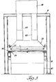
- a glass tempering system generally indicated at 10, includes a furnace 12 for heating glass sheets to a sufficiently high temperature for tempering.
- the system 10 also includes a quench 14 having an air supply system constructed and operated in accordance with the present invention to provide quenching that tempers the heated glass sheets and cooling as is hereinafter more fully described.
- the furnace 12 is preferably of the type disclosed in United States Patents 3,934,970; 3,947,242; and 3,994,711 so as to include an upper housing 16 and a lower housing 18 that cooperatively define a side slot 20 at the opposite lateral sides of the furnace 12.
- a roller conveyor 22 of the furnace 12 includes conveyor rolls 24 whose opposite ends project outwardly through the furnace side slots 20 for frictional driving in the manner disclosed in the aforementioned patents.
- a flat glass sheet to be heated is introduced into the furnace 12 through an access opening at its left end and is conveyed within a suitably heated interior chamber by the conveyor rolls 24 for heating to a sufficiently high temperature (for example, between 1,200° to 1,300° F) for subsequent tempering upon leaving the furnace 12 through an exit opening at its right end adjacent the quench 14.
- a sufficiently high temperature for example, between 1,200° to 1,300° F
- the quench 14 can be utilized to provide heat strengthening of glass sheets by delivering a lower volume flow rate of quenching gas than that necessary to perform the tempering.
- the quench 14 includes upper and lower opposed blastheads 26 and 28 which, in turn, include upper and lower banks of nozzles 27 and 29, respectively.
- the quench 14 also includes a roller conveyor 30 having conveyor rolls 32 for conveying a heated glass sheet G between the blastheads 26 and 28 for quenching and subsequently thereafter for cooling.
- the banks of nozzles 27 and 28 are spaced from each other and supply pressurized quenching gas to the heated glass sheet G positioned between the blastheads on the roller conveyor 30 in a manner which is hereinafter more fully described.
- the quench unit 14 includes a drive system 36 of a fan or blower.
- the blower supplies quenching air through upper and lower ducts 38 and 40, respectively.
- the drive system 36 comprises a variable speed blower motor, a transformer, a drive and switch gear sized or rated to the maximum air pressure required for the thinnest glass to be quenched and cooled in the quench unit 14.
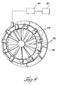
- FIGURE 4 there is illustrated a plurality of adjustable inlet vanes 42 of the blower.
- Each of the vanes 42 are individually driven by motors 44.
- the motors 44 are circumferentially mounted on a circular support structure 46 in driving engagement with their associated vanes 42.
- the motors 44 are automatically controlled by a motor control circuit 48 which, in turn, is controlled by a controller 56.
- the controller 56 which is preferably programmable, also controls the operation of the drive system 36 as shown in FIGURE 2.
- control circuit 48 controls the operation of the motors 44. In this way the vanes 42 are moved between open and closed positions, thereby alternately allowing and restricting the flow of air into the blower.
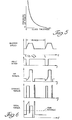
- Pressure and power requirements for tempering glass are hyperbolic functions of glass thickness as indicated in FIGURE 5.
- the pressure and power requirements in providing the quenching gas are functions of the inverse of the drive system.
- the drive system is preferably provided to minimize the power requirements in quenching thin glass such as thin architectural glass. By running the blower at full pressure and the drive system at substantially above its rated power output during quenching and reduced pressure during cooling the power requirements can be minimized by as much as 1/3.
- the size of the quench 14 is reduced to as small an area as possible to improve the planarity of the thin glass when produced on a low production basis. Because the rated power requirement is less than the peak requirement, the blower drive and the blower motor of the blower are down-sized based on the duty cycle of the blower. In this way quench power is minimized and the planarity of the glass sheets is improved.
- FIGURE 6 there is shown in graphic form the operation of the air supply system for one period of a quench and cooling cycle wherein the blower is run intermittently and at different speeds rather than continuously.
- the blower speed increases from the start of the indicated period until quenching speed is achieved.
- the inlet vanes 42 are closed to minimize the air horsepower required as shown in the second graph of FIGURE 6.
- the following table represents a hypothetical operation of the air supply system including the blower to quench and cool four millimeter glass.
- the vanes 42 are held closed while the blower motor is accelerated to a quenching speed of approximately 1,016 rpm. Between times T2 and T3 the blower motor is held at this speed for approximately two seconds with the vanes 42 closed. Between times T3 and T4 the vanes 42 are open while the blower motor speed is maintained to allow the glass sheets to be quenched. After quenching, the power to the blower motor is removed and coasting occurs for a duration of approximately 14 seconds between times T4 and T5 in order to decelerate the blower motor. In order to stop the deceleration, power is applied to the blower motor for approximately one second in order to achieve the cooling speed between times T5 and T6. Between times T6 and T7, the cooling portion of the cooling period is entered which comprises one-half of the period.
- peak power requirements occur between times Tl and T2 and between times T5 and T6.
- This peak power level corresponds to the maximum rating of the blower drive and the blower drive motor.
- the switch gear, the blower motor and the blower drive is sized to the average power consumption or the rms average as shown in the last graph in FIGURE 6 during the quench cooling cycle.
- an average horsepower of 132 is required. 300 horsepower is required during the quench portion of the period and 66 horsepower is required during the cooling portion of the cycle. A similar example for three millimeter glass will require 1252 horsepower during the quench portion of the cycle. However, if the blower is operated on a duty cycle basis, only an 800 horsepower drive and motor are required.
- the quenching and cooling are carried out in a single quench unit 14, and a single blower and ductwork set is required.
- the glass sheets are allowed to enter into the quench unit 14 in a relatively rapid fashion (approximately 150 feet per minute) so that the entire piece of glass is quenched simultaneously, thereby resulting in a flatter piece of glass.
- the blower may also be operated to quench and cool relatively thick glass. -In this situation the motor of the blower is decelerated from a cooling speed to a quench or heat strengthening speed as rapidly as possible after the motor has been accelerated from its quenching speed to its cooling speed. In this way quenching and cooling of relatively thick glass can be obtained in a single quench unit by operating the blower on a duty cycle basis.
Landscapes
- Chemical & Material Sciences (AREA)
- Physics & Mathematics (AREA)
- Thermal Sciences (AREA)
- Engineering & Computer Science (AREA)
- Materials Engineering (AREA)
- Organic Chemistry (AREA)
- Re-Forming, After-Treatment, Cutting And Transporting Of Glass Products (AREA)
Priority Applications (1)
| Application Number | Priority Date | Filing Date | Title |
|---|---|---|---|
| AT84307593T ATE37859T1 (de) | 1983-11-14 | 1984-11-02 | Verfahren und vorrichtung zur zufuehrung der kuehlluft zu einer glasscheibenabschreckstation. |
Applications Claiming Priority (2)
| Application Number | Priority Date | Filing Date | Title |
|---|---|---|---|
| US06/551,572 US4525193A (en) | 1983-11-14 | 1983-11-14 | Method and apparatus for supplying cooling air in a glass sheet quench |
| US551572 | 1983-11-14 |
Publications (2)
| Publication Number | Publication Date |
|---|---|
| EP0145246A1 true EP0145246A1 (de) | 1985-06-19 |
| EP0145246B1 EP0145246B1 (de) | 1988-10-12 |
Family
ID=24201815
Family Applications (1)
| Application Number | Title | Priority Date | Filing Date |
|---|---|---|---|
| EP84307593A Expired EP0145246B1 (de) | 1983-11-14 | 1984-11-02 | Verfahren und Vorrichtung zur Zuführung der Kühlluft zu einer Glasscheibenabschreckstation |
Country Status (17)
| Country | Link |
|---|---|
| US (1) | US4525193A (de) |
| EP (1) | EP0145246B1 (de) |
| JP (1) | JPS60127247A (de) |
| KR (1) | KR910009951B1 (de) |
| AR (1) | AR240665A1 (de) |
| AT (1) | ATE37859T1 (de) |
| AU (1) | AU567584B2 (de) |
| BR (1) | BR8405457A (de) |
| CA (1) | CA1212236A (de) |
| DE (1) | DE3474543D1 (de) |
| EG (1) | EG16898A (de) |
| ES (1) | ES537432A0 (de) |
| FI (1) | FI77635C (de) |
| IE (1) | IE56186B1 (de) |
| IN (1) | IN162775B (de) |
| NZ (1) | NZ209666A (de) |
| ZA (1) | ZA847415B (de) |
Cited By (2)
| Publication number | Priority date | Publication date | Assignee | Title |
|---|---|---|---|---|
| FR2592371A1 (fr) * | 1985-12-27 | 1987-07-03 | Central Glass Co Ltd | Procede pour recuire une feuille de verre par trempe a l'air |
| EP0441804A4 (en) * | 1988-09-29 | 1993-05-19 | Glasstech, Inc. | Glass sheet modulated quenching |
Families Citing this family (16)
| Publication number | Priority date | Publication date | Assignee | Title |
|---|---|---|---|---|
| FI77216C (fi) * | 1987-03-16 | 1989-02-10 | Kyro Oy | Regleringsanordning foer blaostrycket i en glashaerdningsanordnings kylmunstycken. |
| US5917107A (en) * | 1997-11-20 | 1999-06-29 | Glasstech, Inc. | Quench loader for installing glass sheet quench module set |
| US5900034A (en) * | 1997-11-20 | 1999-05-04 | Glasstech, Inc. | Support and actuating mechanism for mold support assembly used for heated glass sheet forming |
| US6032491A (en) | 1997-11-20 | 2000-03-07 | Glasstech, Inc. | Apparatus for mold changing in heated glass sheet forming station |
| US5906668A (en) * | 1997-11-20 | 1999-05-25 | Glasstech, Inc. | Mold assembly for forming heated glass sheets |
| US5925162A (en) * | 1997-11-20 | 1999-07-20 | Glasstech, Inc. | Mold support assembly for heated glass sheet mold |
| US6729160B1 (en) | 1997-11-20 | 2004-05-04 | Glasstech, Inc. | Apparatus and method for forming heated glass sheets |
| KR100370928B1 (ko) * | 2002-06-19 | 2003-02-07 | 유병섭 | 강화유리 제조시스템의 냉각장치 |
| US7958750B2 (en) * | 2005-10-21 | 2011-06-14 | Glasstech, Inc. | Glass sheet forming system |
| US8074473B2 (en) * | 2006-12-01 | 2011-12-13 | Glasstech, Inc. | Method for quenching formed glass sheets |
| US7716949B2 (en) | 2007-04-04 | 2010-05-18 | Glasstech, Inc. | Method for positioning glass sheets for forming |
| JP5428288B2 (ja) * | 2007-12-25 | 2014-02-26 | 日本電気硝子株式会社 | ガラス板の製造方法及び製造設備 |
| US9611166B2 (en) | 2014-10-02 | 2017-04-04 | Glasstech, Inc. | Glass quench apparatus |
| US9758421B2 (en) | 2015-11-02 | 2017-09-12 | Glasstech, Inc. | Glass sheet processing system having cooling of conveyor roller ends |
| US9745147B2 (en) | 2015-11-02 | 2017-08-29 | Glasstech, Inc. | Glass sheet forming system |
| CN108349774B (zh) | 2015-11-02 | 2021-03-30 | 玻璃技术公司 | 玻璃片成形系统 |
Citations (5)
| Publication number | Priority date | Publication date | Assignee | Title |
|---|---|---|---|---|
| US3923488A (en) * | 1974-04-26 | 1975-12-02 | Ppg Industries Inc | Method of tempering flat glass sheets |
| US3936291A (en) * | 1972-08-14 | 1976-02-03 | Mcmaster Harold | Glass sheet tempering blasthead |
| US3947242A (en) * | 1975-02-19 | 1976-03-30 | Mcmaster Harold | Roller hearth furnace for glass sheets |
| US3994711A (en) * | 1975-09-15 | 1976-11-30 | Mcmaster Harold | Glass tempering system including oscillating roller furnace |
| US4004901A (en) * | 1975-10-28 | 1977-01-25 | Ppg Industries, Inc. | Tempering glass sheets |
Family Cites Families (1)
| Publication number | Priority date | Publication date | Assignee | Title |
|---|---|---|---|---|
| IE35468B1 (en) * | 1970-07-29 | 1976-02-18 | Triplex Safety Glass Co | Improvements in or relating to toughened glass sheets |
-
1983
- 1983-11-14 US US06/551,572 patent/US4525193A/en not_active Expired - Lifetime
-
1984
- 1984-09-17 CA CA000463276A patent/CA1212236A/en not_active Expired
- 1984-09-18 IE IE2372/84A patent/IE56186B1/xx unknown
- 1984-09-20 ZA ZA847415A patent/ZA847415B/xx unknown
- 1984-09-24 NZ NZ209666A patent/NZ209666A/en unknown
- 1984-09-28 AU AU33664/84A patent/AU567584B2/en not_active Ceased
- 1984-10-17 JP JP59218179A patent/JPS60127247A/ja active Granted
- 1984-10-18 IN IN786/MAS/84A patent/IN162775B/en unknown
- 1984-10-24 AR AR29836184A patent/AR240665A1/es active
- 1984-10-26 KR KR1019840006667A patent/KR910009951B1/ko not_active Expired
- 1984-10-26 BR BR8405457A patent/BR8405457A/pt not_active IP Right Cessation
- 1984-11-02 EP EP84307593A patent/EP0145246B1/de not_active Expired
- 1984-11-02 DE DE8484307593T patent/DE3474543D1/de not_active Expired
- 1984-11-02 AT AT84307593T patent/ATE37859T1/de not_active IP Right Cessation
- 1984-11-07 ES ES537432A patent/ES537432A0/es active Granted
- 1984-11-13 FI FI844454A patent/FI77635C/fi not_active IP Right Cessation
- 1984-11-13 EG EG700/84A patent/EG16898A/xx active
Patent Citations (6)
| Publication number | Priority date | Publication date | Assignee | Title |
|---|---|---|---|---|
| US3936291A (en) * | 1972-08-14 | 1976-02-03 | Mcmaster Harold | Glass sheet tempering blasthead |
| US3923488A (en) * | 1974-04-26 | 1975-12-02 | Ppg Industries Inc | Method of tempering flat glass sheets |
| US3947242A (en) * | 1975-02-19 | 1976-03-30 | Mcmaster Harold | Roller hearth furnace for glass sheets |
| US3994711A (en) * | 1975-09-15 | 1976-11-30 | Mcmaster Harold | Glass tempering system including oscillating roller furnace |
| US3994711B1 (de) * | 1975-09-15 | 1990-07-03 | Glasstech Inc | |
| US4004901A (en) * | 1975-10-28 | 1977-01-25 | Ppg Industries, Inc. | Tempering glass sheets |
Cited By (2)
| Publication number | Priority date | Publication date | Assignee | Title |
|---|---|---|---|---|
| FR2592371A1 (fr) * | 1985-12-27 | 1987-07-03 | Central Glass Co Ltd | Procede pour recuire une feuille de verre par trempe a l'air |
| EP0441804A4 (en) * | 1988-09-29 | 1993-05-19 | Glasstech, Inc. | Glass sheet modulated quenching |
Also Published As
| Publication number | Publication date |
|---|---|
| AU3366484A (en) | 1985-05-23 |
| IN162775B (de) | 1988-07-09 |
| FI77635B (fi) | 1988-12-30 |
| ES8601074A1 (es) | 1985-10-16 |
| EP0145246B1 (de) | 1988-10-12 |
| KR850004734A (ko) | 1985-07-27 |
| CA1212236A (en) | 1986-10-07 |
| NZ209666A (en) | 1986-06-11 |
| ES537432A0 (es) | 1985-10-16 |
| FI844454A0 (fi) | 1984-11-13 |
| IE56186B1 (en) | 1991-05-08 |
| FI844454L (fi) | 1985-05-15 |
| JPS60127247A (ja) | 1985-07-06 |
| JPS6247820B2 (de) | 1987-10-09 |
| IE842372L (en) | 1985-05-14 |
| AU567584B2 (en) | 1987-11-26 |
| AR240665A1 (es) | 1990-08-31 |
| ATE37859T1 (de) | 1988-10-15 |
| KR910009951B1 (ko) | 1991-12-07 |
| US4525193A (en) | 1985-06-25 |
| DE3474543D1 (en) | 1988-11-17 |
| FI77635C (fi) | 1989-04-10 |
| BR8405457A (pt) | 1985-09-03 |
| EG16898A (en) | 1991-08-30 |
| ZA847415B (en) | 1985-04-24 |
Similar Documents
| Publication | Publication Date | Title |
|---|---|---|
| EP0145246B1 (de) | Verfahren und Vorrichtung zur Zuführung der Kühlluft zu einer Glasscheibenabschreckstation | |
| EP0010854B1 (de) | Verfahren zur Wärmebehandlung sich bewegender Glasscheiben in einem modifizierten Gasbett | |
| EP0721922A1 (de) | Verfahren zum Erwärmen von Glastafeln, die getempert oder durch Wärme gehärtet werden sollen | |
| DE69702982D1 (de) | Ofen für die wärmebehandlung von glasscheiben | |
| US20020020192A1 (en) | Method for making a curved glass-ceramic panel by bending a green glass panel to be ceramicized and apparatus for performing said method | |
| FI101621B (fi) | Menetelmä karkaistujen lasilevyjen heat-soak käsittelyä varten | |
| CN105693071A (zh) | 用于玻璃加热的气浮装置 | |
| CN111908781A (zh) | 一种连续式玻璃钢化炉中加热炉的输送方法 | |
| CN112939434B (zh) | 一种玻璃生产的钢化炉 | |
| CN107502724A (zh) | 螺栓热处理系统和方法 | |
| CN105621874B (zh) | 用于玻璃板回火的方法 | |
| CN110498598B (zh) | 可提高产能的半钢化玻璃冷却系统及半钢化玻璃生产工艺 | |
| US4028051A (en) | Curing oven for mineral wool | |
| US4886540A (en) | Blow back control device for a glass sheet tempering system | |
| EP4008693B1 (de) | Windauslassstruktur und kühlvorrichtung | |
| CN110698045A (zh) | 一种多区域温度可控的气浮加热薄玻璃的装置及其工作方法 | |
| US4311507A (en) | Special entrance slit module and method for quenching glass sheets | |
| CN219347201U (zh) | 一种烘干装置 | |
| CN219546877U (zh) | 一种钢化玻璃加工用快速冷却装置 | |
| CN210287134U (zh) | 一种玻璃钢化炉 | |
| CN222844548U (zh) | 一种具有调节功能的板材风冷定型机 | |
| CN202667490U (zh) | 紫铜锻件快速冷却切边传输装置 | |
| CN220541770U (zh) | 一种瓷砖生产区过道降温装置 | |
| CN104291667B (zh) | 玻璃基板的快速连续移动洁净冷却系统 | |
| KR20000058044A (ko) | 편평 제품과의 열교환용 장치 |
Legal Events
| Date | Code | Title | Description |
|---|---|---|---|
| PUAI | Public reference made under article 153(3) epc to a published international application that has entered the european phase |
Free format text: ORIGINAL CODE: 0009012 |
|
| AK | Designated contracting states |
Designated state(s): AT BE CH DE FR GB IT LI LU NL SE |
|
| 17P | Request for examination filed |
Effective date: 19851204 |
|
| 17Q | First examination report despatched |
Effective date: 19860818 |
|
| GRAA | (expected) grant |
Free format text: ORIGINAL CODE: 0009210 |
|
| AK | Designated contracting states |
Kind code of ref document: B1 Designated state(s): AT BE CH DE FR GB IT LI LU NL SE |
|
| PG25 | Lapsed in a contracting state [announced via postgrant information from national office to epo] |
Ref country code: CH Effective date: 19881012 Ref country code: NL Effective date: 19881012 Ref country code: AT Effective date: 19881012 Ref country code: LI Effective date: 19881012 Ref country code: SE Effective date: 19881012 |
|
| REF | Corresponds to: |
Ref document number: 37859 Country of ref document: AT Date of ref document: 19881015 Kind code of ref document: T |
|
| REF | Corresponds to: |
Ref document number: 3474543 Country of ref document: DE Date of ref document: 19881117 |
|
| PGFP | Annual fee paid to national office [announced via postgrant information from national office to epo] |
Ref country code: AT Payment date: 19881123 Year of fee payment: 5 |
|
| PGFP | Annual fee paid to national office [announced via postgrant information from national office to epo] |
Ref country code: NL Payment date: 19881130 Year of fee payment: 5 |
|
| REG | Reference to a national code |
Ref country code: CH Ref legal event code: PL |
|
| EN | Fr: translation not filed | ||
| NLV1 | Nl: lapsed or annulled due to failure to fulfill the requirements of art. 29p and 29m of the patents act | ||
| ITF | It: translation for a ep patent filed | ||
| PLBE | No opposition filed within time limit |
Free format text: ORIGINAL CODE: 0009261 |
|
| STAA | Information on the status of an ep patent application or granted ep patent |
Free format text: STATUS: NO OPPOSITION FILED WITHIN TIME LIMIT |
|
| 26N | No opposition filed | ||
| ET | Fr: translation filed | ||
| REG | Reference to a national code |
Ref country code: FR Ref legal event code: BR |
|
| ITTA | It: last paid annual fee | ||
| PGFP | Annual fee paid to national office [announced via postgrant information from national office to epo] |
Ref country code: LU Payment date: 19931001 Year of fee payment: 10 |
|
| PGFP | Annual fee paid to national office [announced via postgrant information from national office to epo] |
Ref country code: GB Payment date: 19931011 Year of fee payment: 10 |
|
| PGFP | Annual fee paid to national office [announced via postgrant information from national office to epo] |
Ref country code: FR Payment date: 19931110 Year of fee payment: 10 |
|
| PGFP | Annual fee paid to national office [announced via postgrant information from national office to epo] |
Ref country code: DE Payment date: 19931126 Year of fee payment: 10 |
|
| PGFP | Annual fee paid to national office [announced via postgrant information from national office to epo] |
Ref country code: BE Payment date: 19931210 Year of fee payment: 10 |
|
| EPTA | Lu: last paid annual fee | ||
| PG25 | Lapsed in a contracting state [announced via postgrant information from national office to epo] |
Ref country code: GB Effective date: 19941102 Ref country code: LU Free format text: LAPSE BECAUSE OF NON-PAYMENT OF DUE FEES Effective date: 19941102 |
|
| PG25 | Lapsed in a contracting state [announced via postgrant information from national office to epo] |
Ref country code: BE Effective date: 19941130 |
|
| BERE | Be: lapsed |
Owner name: GLASSTECH INC. Effective date: 19941130 |
|
| GBPC | Gb: european patent ceased through non-payment of renewal fee |
Effective date: 19941102 |
|
| PG25 | Lapsed in a contracting state [announced via postgrant information from national office to epo] |
Ref country code: DE Effective date: 19950801 |
|
| PG25 | Lapsed in a contracting state [announced via postgrant information from national office to epo] |
Ref country code: FR Effective date: 19950831 |
|
| REG | Reference to a national code |
Ref country code: FR Ref legal event code: ST |
|
| PG25 | Lapsed in a contracting state [announced via postgrant information from national office to epo] |
Ref country code: FR Effective date: 19941130 |