EP4008693B1 - Windauslassstruktur und kühlvorrichtung - Google Patents
Windauslassstruktur und kühlvorrichtung Download PDFInfo
- Publication number
- EP4008693B1 EP4008693B1 EP20212311.3A EP20212311A EP4008693B1 EP 4008693 B1 EP4008693 B1 EP 4008693B1 EP 20212311 A EP20212311 A EP 20212311A EP 4008693 B1 EP4008693 B1 EP 4008693B1
- Authority
- EP
- European Patent Office
- Prior art keywords
- wind
- wind outlet
- windshield
- outlet structure
- perforations
- Prior art date
- Legal status (The legal status is an assumption and is not a legal conclusion. Google has not performed a legal analysis and makes no representation as to the accuracy of the status listed.)
- Active
Links
Images


Classifications
-
- C—CHEMISTRY; METALLURGY
- C03—GLASS; MINERAL OR SLAG WOOL
- C03B—MANUFACTURE, SHAPING, OR SUPPLEMENTARY PROCESSES
- C03B27/00—Tempering or quenching glass products
- C03B27/04—Tempering or quenching glass products using gas
- C03B27/0404—Nozzles, blow heads, blowing units or their arrangements, specially adapted for flat or bent glass sheets
Definitions
- the present disclosure relates to a glass cooling processing technology, and in particular to a wind outlet structure and cooling device that can control an appropriate number of wind outlet holes for wind supply operation according to a size of the glass.
- Glass has excellent transmittance and scratch resistance, so it is widely used in daily life. At present, related glass products can be seen not only in buildings and general daily necessities, but also in electronic appliances and vehicles. Peripheral products have flooded people's lives.
- the glass is made by batching, melting, forming, annealing and other processes. After the glass is made, further processing operations can be performed to improve the functionality of the glass. For example, the annealed glass can be cut to the required size, then the glass is heated by a glass heating furnace to soften the glass, and then the glass is rapidly cooled through a cooling device to cool the glass surface below the annealing temperature for rapid hardening and shrinking. When interior of the glass shrinks, it will cause a compressive stress on the surface, and the interior of the glass will produce a tensile stress, which can increase the strength of the glass to form a so-called strengthened glass.
- the cooling device at least comprises wind outlet structures laterally arranged above and below.
- wind outlet structures laterally arranged above and below.
- the rollers can carry glass, and then use the wind outlet structure to output wind and blow it toward the glass, so as to achieve the purpose of rapid cooling of the glass.
- Documents JP 2001192226 A and US 3 522 029 A disclose some glass cooling solutions. More specifically, document JP 2001192226 A teaches a glass cooling processing device, in which a wind outlet structure according to the preamble of claim 1 is provided with manually adjustable opening and closing ranges of nozzles for supplying cooling air to a glass sheet to be cooled.
- Document US 3 522 029 A relates to a method of reshaping glass sheets by differential cooling, the glass sheet bending and tempering system known therefrom includes a cooling apparatus defining a wind outlet structure, which comprises a plurality of wind outlet parts having multiple outlets and further comprises valve plates with perforations, wherein the valve plates are shiftable, such that the perforations are communicated with or offset to the outlets.
- the objective of the present disclosure is to provide a wind outlet structure and a cooling device that can control an appropriate number of wind outlet holes to perform wind supply operation according to the size of the glass.
- a wind outlet structure for a glass sheet cooling device comprises: a case, wherein interior of the case forms a wind inlet channel; at least one wind outlet part, wherein the wind outlet part is connected to one surface of the case, interior of the wind outlet part forms a wind outlet channel communicated with the wind inlet channel, and another one surface of the wind outlet part opposite to the surface of wind outlet part which is connected to the case has a plurality of wind outlet holes; at least one windshield, wherein the windshield is disposed in the wind outlet channel of the wind outlet part, and the windshield has a plurality of perforations; wherein the other surface of the wind outlet part opposite to the surface of wind outlet part, which is connected to the case, is a curved surface or an irregular surface, and the wind outlet holes are set on different angled surfaces; and the wind outlet structure is further provided with at least one controller controller disposed in the wind outlet channel of the wind outlet part and connected to the windshield, the controller controls the windshield to move laterally, such that
- a number of the perforations is less than a number of the wind outlet holes.
- the windshield occupies less than half a length of the wind outlet channel.
- the wind outlet holes and the perforations are arranged in a plurality of rows
- a number of the rows in which the perforations are arranged is equal to a number of the rows in which the wind outlet holes are arranged.
- a displacement of the windshield is 10 mm.
- the wind outlet structure further comprises a connecting pipe connected to the case, wherein one end of the connecting pipe is a wind inlet hole, and the wind inlet hole is connected to the wind inlet channel.
- a cooling device comprises: a motor; a wind blower connected to the motor; a first wind supply pipe having one end connected to the wind blower; a wind box connected to another end of the first wind supply pipe opposite to the end of the first wind supply pipe which is connected to the wind blower; a plurality of second wind supply pipes, wherein one end of each second wind supply pipe is connected to the wind box; and the wind outlet structures as mentioned above, the connecting pipe of each wind outlet structure is connected to another one end of the second wind supply pipe opposite to the end of the second wind supply pipe which is connected to the wind box.
- the wind outlet structure has a windshield and a controller, both of which are disposed in the wind outlet channel of the wind outlet part.
- the windshield moves laterally, so that part or all of the wind outlet holes of the wind outlet part can be selectively shielded through the windshield, so that the cooling device can control an appropriate number of the wind outlet holes for air supply operation according to the glass size when the cooling device operates, thereby achieving the purpose of energy saving and cost reduction.
- the wind outlet structure and the cooling device of the present disclosure can be applied to glass cooling processing technology. After the glass is heated and softened by a heating furnace, the present disclosure can be used to rapidly cool the glass, so that the glass can be rapidly hardened and contracted, thereby improving the strength of glass.
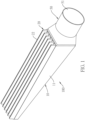
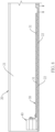
- the wind outlet structure 100 of the present disclosure at least comprises a case 10, at least one wind outlet part 20, at least one windshield 30, at least one controller 40 and a connecting pipe 50, wherein the numbers of the wind outlet parts 20, the windshields 30 and the controllers 40 match to each other, that is, one windshield 30 and one controller40 are disposed in each wind outlet part 20, and in such structure configuration, the numbers of the wind outlet parts 20, the windshields 30 and the controllers 40 are six, and the present disclosure is not limited to the numbers of the wind outlet parts 20, the windshields 30 and the controllers 40.
- the interior of the case 10 forms a wind inlet channel 11; the wind outlet part 20 is connected to one surface of the case 10, the interior of the wind outlet part 20 forms a wind outlet channel 21 communicated with the wind inlet channel 11, and the other surface of the wind outlet part 20 opposite to the surface of the wind outlet part which is connected to the case 10 is provided with a plurality of wind outlet holes 22, wherein the wind outlet part 20 is formed by metal extrusion molding, preferably aluminum extrusion molding, and the wind outlet part 20 can be connected to the case10 by screwing, but the present disclosure is not limited.
- the wind is allowed to enter the wind inlet hole 51 of the connecting pipe 50, and the wind can be output through the wind outlet holes 22 of the wind outlet part 20 after passing through the wind inlet channel 11 of the case 10 and the wind outlet channel 21 of the wind outlet part 20, thereby cooling the glass.
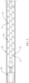
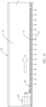
- the controller 40 can control the lateral displacement of the windshield 30 in the wind outlet channel 21, so that the perforations 31 and the wind outlet holes 22 can be communicated with or offset to each other.
- the windshield 30 can shield a part or all of the wind outlet holes 22 of the wind outlet part 20, so that the purpose of controlling an appropriate number of the wind outlet holes 22 for wind supply operation according to the glass size can be achieved.
- the displacement of the windshield 30 can be set to 10mm, but the present disclosure is not limited to this.
- the number of the perforations 31 of the windshield 30 is less than the number of the wind outlet holes 22 of the wind outlet part 20; or alternatively, the windshield 30 occupies less than half the length of the wind outlet channel 21 of the wind outlet part 20.
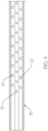
- FIG. 4 is a schematic diagram showing an arrangement of wind outlet holes of a wind outlet part in a wind outlet structure according to a first embodiment of the present disclosure
- FIG. 5 is a schematic diagram showing an arrangement of perforations of a windshield in a wind outlet structure according to a first embodiment of the present disclosure.
- the wind outlet holes 22 of the wind outlet part 20 of the present disclosure are arranged in rows.
- the wind outlet holes 22 are disposed in three rows, and the perforations 31 of the windshield 30 of the present disclosure are disposed in rows.
- the number of the rows of the perforations 31 and the number of the rows of the wind outlet holes 22 are the same one.
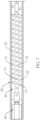
- FIG. 6 through FIG. 10 are respectively a first through fifth schematic diagrams showing a wind outlet structure according to a first embodiment of the present disclosure.
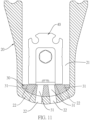
- the other surface of the wind outlet part 20 having the wind outlet holes 22 is a curved surface or an irregular surface, and the wind outlet holes 22 are set on different angled surfaces.
- the wind outlet holes 22 are arranged in three rows, and the wind outlet holes 22 in each row are respectively located at different angled surfaces, so that the wind outlet holes 22 in each row can be output the wind in different directions to enhance the cooling effect.
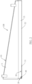
- the length of the windshield 30 is less than the length of the wind outlet channel 21 of the wind outlet part 20, and the arrangement of the perforation 31 of the windshield 30 corresponds to the arrangement of the wind outlet holes 22.
- the controller 40 can control the displacement of the windshield 30 so that the perforations 31 in each row are offset to the wind outlet holes 22 in the corresponding rows.
- the part of the wind outlet holes 22 of the wind outlet part 20 are shielded, as shown in FIG. 7 and FIG. 8 .
- the windshield 30 is displaced by the control of the controller 40 so that all the perforations 31 of each row can be communicated with all the wind outlet holes 22 of each row, as shown in FIG. 9 and FIG. 10 .
- FIG. 11 is a schematic diagram showing a wind outlet structure according to a second embodiment of the present disclosure.
- the wind outlet holes 22 and the perforation 31 are respectively arranged in four rows, and the wind outlet holes 22 in each row are respectively located on different angled surfaces.
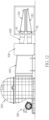
- FIG. 12 is a schematic diagram showing a cooling device of the present disclosure.
- the cooling device comprises a motor 200, a wind blower 300, a first wind supply pipe 400, a wind box 500, second wind supply pipes 600 and the wind outlet structures 100 as mentioned above.
- the wind blower 300 is connected to the motor 200; one end of the first wind supply pipe 400 is connected to the wind blower 300; the wind box 500 is connected to the other end of the first wind supply pipe 400 opposite to the end of the first wind supply pipe 400 which is connected to the wind blower 300; one end of each second wind supply pipe 600 is connected to the wind box 500; and the connecting pipe 50 of the wind outlet structure 100 is connected to the other end of the second wind supply pipe 600 opposite to the end of the second wind supply pipe 600 which is connected to the wind box 500.
- the wind outlet structures 100 of the cooling device are set up and down at intervals.
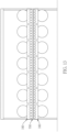
- FIG. 13 is a schematic diagram showing glass cooling operation by using a cooling device of the present disclosure.
- the wind outlet structures 100 of the cooling device of the present disclosure laterally arranged above and below, and rollers 700 are arranged between the above and below wind outlet structures 100.
- the rollers 700 is used to carry the glass, the upper and below wind outlet structures 100 can individually control the number of wind outlet holes for supplying wind according to the size of the glass.
- the wind outlet channel of the wind outlet part is disposed with the windshield and the controller.
- the windshield moved laterally by the control/driving of the controller, so that the windshield moves to selectively shield part or all of the wind outlet holes of the wind outlet part. Therefore, the cooling device can control an appropriate number of wind outlet holes for wind supply operation according to the glass size when the cooling device operates, so as to achieve the purpose of energy saving and cost reduction.
Landscapes
- Chemical & Material Sciences (AREA)
- Physics & Mathematics (AREA)
- Thermal Sciences (AREA)
- Engineering & Computer Science (AREA)
- Materials Engineering (AREA)
- Organic Chemistry (AREA)
- Re-Forming, After-Treatment, Cutting And Transporting Of Glass Products (AREA)
Claims (9)
- Windauslassstruktur für eine Glaskühlvorrichtung, umfassend:ein Gehäuse (10), wobei im Inneren des Gehäuses (10) ein Windeinlasskanal (11) gebildet ist; mindestens einen Windauslassteil (20), wobei der Windauslassteil (20) mit einer Oberfläche des Gehäuses (10) verbunden ist, das Innere des Windauslassteils (20) einen Windauslasskanal (21) bildet, der mit dem Windeinlasskanal (11) verbunden ist, eine weitere Fläche des Windauslassteils (20), die der Oberfläche des Windauslassteils (20) gegenüberliegt und die mit dem Gehäuse (10) verbunden ist, mehrere Windauslasslöcher (22) aufweist; und mindestens eine Windschutzscheibe (30), wobei die Windschutzscheibe (30) im Windauslasskanal (21) des Windauslassteils (20) angeordnet ist und die Windschutzscheibe (30) mehrere Perforierungen (31) aufweist;dadurch gekennzeichnet, dassdie andere Oberfläche des Windauslassteils (20), die der Oberfläche des Windauslassteils (20) gegenüberliegt und die mit dem Gehäuse (10) verbunden ist, eine gekrümmte Oberfläche oder eine unregelmäßige Oberfläche aufweist, während die Windauslasslöcher (22) auf unterschiedlich abgewinkelten Flächen angeordnet sind; die Windauslassstruktur weiter mit mindestens einem Regler (40) versehen ist, der im Windauslasskanal (21) des Windauslassteils (20) angeordnet und an der Windschutzscheibe (30) befestigt ist, wobei der Regler (40) steuert, dass sich die Windschutzscheibe (30) seitlich bewegt wird, so dass die Perforierungen (31) mit den Windauslasslöchern (22) verbunden oder versetzt sind.
- Windauslassstruktur nach Anspruch 1, wobei eine Anzahl der Perforierungen (31) geringer als eine Anzahl der Windauslasslöcher (22) ist.
- Windauslassstruktur nach Anspruch 1 oder 2, wobei die Windschutzscheibe (30) weniger als eine halbe Länge des Windauslasskanals (21) einnimmt.
- Windauslassstruktur nach Anspruch 1 oder 2 oder 3, wobei die Windauslasslöcher (22) und die Perforierungen (31) in mehreren Reihen angeordnet sind.
- Windauslassstruktur nach Anspruch 4, wobei die Anzahl der Reihen, in denen die Perforierungen (31) angeordnet sind, der Anzahl der Reihen entspricht, in denen die Windauslasslöcher (22) angeordnet sind.
- Windauslassstruktur nach einem der Ansprüche, wobei eine Verschiebung der Windschutzscheibe (30) 10 mm beträgt.
- Windauslassstruktur nach einem der Ansprüche, wobei der Windauslassteil (20) aus Metallextrusionsformen hergestellt ist.
- Windauslassstruktur nach einem der Ansprüche, weiter umfassend:
eine Verbindungsleitung (50), die mit dem Gehäuse (10) verbunden ist, wobei ein Ende der Verbindungsleitung (50) ein Windeinlassloch (51) ist, wobei das Windeinlassloch (51) mit dem Windeinlasskanal (11) verbunden ist. - Kühlvorrichtung für Glasscheiben, umfassend, einen Motor (200);ein Windgebläse (300), das mit dem Motor (200) verbunden ist;eine erste Windzufuhrleitung (400), deren ein Ende mit dem Windgebläse (300) verbunden ist; einen Windkasten (500), der mit einem anderen Ende der ersten Windzufuhrleitung (400) gegenüber dem Ende der ersten Windzufuhrleitung (400) verbunden ist, das mit dem Windgebläse (300) verbunden ist;mehrere zweite Windzufuhrleitungen (600), wobei ein Ende jeder zweiten Windzufuhrleitung (600) mit dem Windkasten (500) verbunden ist; und mehrere Windauslassstrukturen (100) nach Anspruch 8, wobei die Verbindungsleitung (50) jeder Windauslassstruktur (100) mit einem anderen Ende der zweiten Windzufuhrleitung (600) gegenüber dem Ende der zweiten Windzufuhrleitung (600) verbunden ist, wobei die Windzufuhrleitung (600) mit dem Windkasten (500) verbunden ist.
Priority Applications (1)
| Application Number | Priority Date | Filing Date | Title |
|---|---|---|---|
| EP20212311.3A EP4008693B1 (de) | 2020-12-07 | 2020-12-07 | Windauslassstruktur und kühlvorrichtung |
Applications Claiming Priority (1)
| Application Number | Priority Date | Filing Date | Title |
|---|---|---|---|
| EP20212311.3A EP4008693B1 (de) | 2020-12-07 | 2020-12-07 | Windauslassstruktur und kühlvorrichtung |
Publications (3)
| Publication Number | Publication Date |
|---|---|
| EP4008693A1 EP4008693A1 (de) | 2022-06-08 |
| EP4008693C0 EP4008693C0 (de) | 2025-02-12 |
| EP4008693B1 true EP4008693B1 (de) | 2025-02-12 |
Family
ID=73740346
Family Applications (1)
| Application Number | Title | Priority Date | Filing Date |
|---|---|---|---|
| EP20212311.3A Active EP4008693B1 (de) | 2020-12-07 | 2020-12-07 | Windauslassstruktur und kühlvorrichtung |
Country Status (1)
| Country | Link |
|---|---|
| EP (1) | EP4008693B1 (de) |
Families Citing this family (1)
| Publication number | Priority date | Publication date | Assignee | Title |
|---|---|---|---|---|
| CN120987555A (zh) * | 2025-10-24 | 2025-11-21 | 咸阳彩虹光伏玻璃有限公司 | 一种全钢玻璃生产用输送过渡段冷却装置 |
Family Cites Families (2)
| Publication number | Priority date | Publication date | Assignee | Title |
|---|---|---|---|---|
| US3522029A (en) * | 1966-12-22 | 1970-07-28 | Libbey Owens Ford Co | Method of reshaping glass sheets by differential cooling |
| JP2001192226A (ja) * | 1999-12-28 | 2001-07-17 | Central Glass Co Ltd | ガラス板の強化方法および装置 |
-
2020
- 2020-12-07 EP EP20212311.3A patent/EP4008693B1/de active Active
Also Published As
| Publication number | Publication date |
|---|---|
| EP4008693C0 (de) | 2025-02-12 |
| EP4008693A1 (de) | 2022-06-08 |
Similar Documents
| Publication | Publication Date | Title |
|---|---|---|
| US20120152410A1 (en) | Method And Device for Energy-Efficient Hot Forming | |
| DD294579A5 (de) | Anlage zur herstellung von glasscheiben | |
| KR20220035282A (ko) | 금속 합금 박판으로 부품을 성형하는 방법 | |
| EP4008693B1 (de) | Windauslassstruktur und kühlvorrichtung | |
| CA1212236A (en) | Method and apparatus for supplying cooling air in a glass sheet quench | |
| JPS55104935A (en) | Tempered glass plate, said plate manufacturing method and apparatus | |
| US20220169552A1 (en) | Wind outlet structure and cooling device | |
| CN111908781A (zh) | 一种连续式玻璃钢化炉中加热炉的输送方法 | |
| EP4026812B1 (de) | Energiesparender windkasten und kühlvorrichtung | |
| CN108483885B (zh) | 一种2mm玻璃的钢化方法 | |
| CN113524732B (zh) | 整形装置 | |
| CN110818234A (zh) | 一种大球面玻璃成型工艺 | |
| GB2601487A (en) | Wind outlet structure and cooling device | |
| US11713270B2 (en) | Energy-saving wind box, cooling device and energy-saving cooling system | |
| TWM606936U (zh) | 出風機構及冷卻設備 | |
| CN101569898B (zh) | 靶材的制作方法 | |
| GB2602492A (en) | Energy-Saving Wind Box, Cooling Device And Energy-Saving Cooling System | |
| TWI750852B (zh) | 出風機構及冷卻設備 | |
| CN211255989U (zh) | 一种钢丝退火装置 | |
| CN104891796B (zh) | 一种玻璃钢化方法 | |
| CN220056664U (zh) | 一种油墨玻璃生产用热交换炉及生产线 | |
| CN212425861U (zh) | 一种玻璃钢化炉可调节风嘴机构 | |
| CN102848156B (zh) | 传动轴中间突缘加工方法 | |
| GB2603557A (en) | Energy-saving wind box, cooling device and energy-saving cooling system | |
| CN115368004B (zh) | 一种超短连续炉钢化玻璃的方法 |
Legal Events
| Date | Code | Title | Description |
|---|---|---|---|
| PUAI | Public reference made under article 153(3) epc to a published international application that has entered the european phase |
Free format text: ORIGINAL CODE: 0009012 |
|
| STAA | Information on the status of an ep patent application or granted ep patent |
Free format text: STATUS: REQUEST FOR EXAMINATION WAS MADE |
|
| 17P | Request for examination filed |
Effective date: 20220216 |
|
| AK | Designated contracting states |
Kind code of ref document: A1 Designated state(s): AL AT BE BG CH CY CZ DE DK EE ES FI FR GB GR HR HU IE IS IT LI LT LU LV MC MK MT NL NO PL PT RO RS SE SI SK SM TR |
|
| GRAP | Despatch of communication of intention to grant a patent |
Free format text: ORIGINAL CODE: EPIDOSNIGR1 |
|
| STAA | Information on the status of an ep patent application or granted ep patent |
Free format text: STATUS: GRANT OF PATENT IS INTENDED |
|
| INTG | Intention to grant announced |
Effective date: 20240829 |
|
| GRAS | Grant fee paid |
Free format text: ORIGINAL CODE: EPIDOSNIGR3 |
|
| GRAA | (expected) grant |
Free format text: ORIGINAL CODE: 0009210 |
|
| STAA | Information on the status of an ep patent application or granted ep patent |
Free format text: STATUS: THE PATENT HAS BEEN GRANTED |
|
| AK | Designated contracting states |
Kind code of ref document: B1 Designated state(s): AL AT BE BG CH CY CZ DE DK EE ES FI FR GB GR HR HU IE IS IT LI LT LU LV MC MK MT NL NO PL PT RO RS SE SI SK SM TR |
|
| REG | Reference to a national code |
Ref country code: GB Ref legal event code: FG4D |
|
| REG | Reference to a national code |
Ref country code: CH Ref legal event code: EP |
|
| REG | Reference to a national code |
Ref country code: DE Ref legal event code: R096 Ref document number: 602020045856 Country of ref document: DE |
|
| REG | Reference to a national code |
Ref country code: IE Ref legal event code: FG4D |
|
| U01 | Request for unitary effect filed |
Effective date: 20250312 |
|
| U07 | Unitary effect registered |
Designated state(s): AT BE BG DE DK EE FI FR IT LT LU LV MT NL PT RO SE SI Effective date: 20250320 |
|
| PG25 | Lapsed in a contracting state [announced via postgrant information from national office to epo] |
Ref country code: RS Free format text: LAPSE BECAUSE OF FAILURE TO SUBMIT A TRANSLATION OF THE DESCRIPTION OR TO PAY THE FEE WITHIN THE PRESCRIBED TIME-LIMIT Effective date: 20250512 |
|
| PG25 | Lapsed in a contracting state [announced via postgrant information from national office to epo] |
Ref country code: PL Free format text: LAPSE BECAUSE OF FAILURE TO SUBMIT A TRANSLATION OF THE DESCRIPTION OR TO PAY THE FEE WITHIN THE PRESCRIBED TIME-LIMIT Effective date: 20250212 |
|
| PG25 | Lapsed in a contracting state [announced via postgrant information from national office to epo] |
Ref country code: ES Free format text: LAPSE BECAUSE OF FAILURE TO SUBMIT A TRANSLATION OF THE DESCRIPTION OR TO PAY THE FEE WITHIN THE PRESCRIBED TIME-LIMIT Effective date: 20250212 |
|
| PG25 | Lapsed in a contracting state [announced via postgrant information from national office to epo] |
Ref country code: NO Free format text: LAPSE BECAUSE OF FAILURE TO SUBMIT A TRANSLATION OF THE DESCRIPTION OR TO PAY THE FEE WITHIN THE PRESCRIBED TIME-LIMIT Effective date: 20250512 Ref country code: IS Free format text: LAPSE BECAUSE OF FAILURE TO SUBMIT A TRANSLATION OF THE DESCRIPTION OR TO PAY THE FEE WITHIN THE PRESCRIBED TIME-LIMIT Effective date: 20250612 |
|
| PG25 | Lapsed in a contracting state [announced via postgrant information from national office to epo] |
Ref country code: HR Free format text: LAPSE BECAUSE OF FAILURE TO SUBMIT A TRANSLATION OF THE DESCRIPTION OR TO PAY THE FEE WITHIN THE PRESCRIBED TIME-LIMIT Effective date: 20250212 |
|
| PG25 | Lapsed in a contracting state [announced via postgrant information from national office to epo] |
Ref country code: GR Free format text: LAPSE BECAUSE OF FAILURE TO SUBMIT A TRANSLATION OF THE DESCRIPTION OR TO PAY THE FEE WITHIN THE PRESCRIBED TIME-LIMIT Effective date: 20250513 |
|
| PG25 | Lapsed in a contracting state [announced via postgrant information from national office to epo] |
Ref country code: SM Free format text: LAPSE BECAUSE OF FAILURE TO SUBMIT A TRANSLATION OF THE DESCRIPTION OR TO PAY THE FEE WITHIN THE PRESCRIBED TIME-LIMIT Effective date: 20250212 |
|
| PG25 | Lapsed in a contracting state [announced via postgrant information from national office to epo] |
Ref country code: CZ Free format text: LAPSE BECAUSE OF FAILURE TO SUBMIT A TRANSLATION OF THE DESCRIPTION OR TO PAY THE FEE WITHIN THE PRESCRIBED TIME-LIMIT Effective date: 20250212 |
|
| PG25 | Lapsed in a contracting state [announced via postgrant information from national office to epo] |
Ref country code: SK Free format text: LAPSE BECAUSE OF FAILURE TO SUBMIT A TRANSLATION OF THE DESCRIPTION OR TO PAY THE FEE WITHIN THE PRESCRIBED TIME-LIMIT Effective date: 20250212 |