EP0145025B1 - Seriendrucker mit mehreren Schreibköpfen - Google Patents
Seriendrucker mit mehreren Schreibköpfen Download PDFInfo
- Publication number
- EP0145025B1 EP0145025B1 EP84115432A EP84115432A EP0145025B1 EP 0145025 B1 EP0145025 B1 EP 0145025B1 EP 84115432 A EP84115432 A EP 84115432A EP 84115432 A EP84115432 A EP 84115432A EP 0145025 B1 EP0145025 B1 EP 0145025B1
- Authority
- EP
- European Patent Office
- Prior art keywords
- print heads
- multihead
- carriages
- platen
- Prior art date
- Legal status (The legal status is an assumption and is not a legal conclusion. Google has not performed a legal analysis and makes no representation as to the accuracy of the status listed.)
- Expired - Lifetime
Links
- 230000007246 mechanism Effects 0.000 claims description 26
- 238000010586 diagram Methods 0.000 description 3
- 238000000034 method Methods 0.000 description 3
- 230000004048 modification Effects 0.000 description 3
- 238000012986 modification Methods 0.000 description 3
- 239000011295 pitch Substances 0.000 description 3
- 239000011159 matrix material Substances 0.000 description 2
- 230000008901 benefit Effects 0.000 description 1
- 230000008859 change Effects 0.000 description 1
- 238000010276 construction Methods 0.000 description 1
- 230000000694 effects Effects 0.000 description 1
- 238000012840 feeding operation Methods 0.000 description 1
- 230000004044 response Effects 0.000 description 1
Images


Classifications
-
- B—PERFORMING OPERATIONS; TRANSPORTING
- B41—PRINTING; LINING MACHINES; TYPEWRITERS; STAMPS
- B41J—TYPEWRITERS; SELECTIVE PRINTING MECHANISMS, i.e. MECHANISMS PRINTING OTHERWISE THAN FROM A FORME; CORRECTION OF TYPOGRAPHICAL ERRORS
- B41J3/00—Typewriters or selective printing or marking mechanisms characterised by the purpose for which they are constructed
- B41J3/54—Typewriters or selective printing or marking mechanisms characterised by the purpose for which they are constructed with two or more sets of type or printing elements
Definitions
- the present invention relates to a multihead serial printer having a plurality of print heads arranged along a horizontal or character-spacing direction.
- One known multihead printer is disclosed in Japanese Laid-Open Patent Publication No. 58-163670.
- the disclosed printer has a plurality of print heads and is selectively operable between a high-speed printing mode and a high-density printing mode.
- There is another known printer having a print head and a pen head both mounted on a single carriage, the printer being switchable between a mode in which the printer operates as a printer and another mode in which the printer operates as a plotter.
- the plurality of print heads are driven by a single motor, and each print head has a fixed print area.
- the printing speed is higher in proportion to the number of print heads used in the case where characters to be printed along one line are uniformly dispersed fully across the line.
- Patent Abstracts of Japan, Vol. 5, No. 50 (M-62) JP-A-565 775) discloses a multihead serial printer having a plurality of print heads arranged along the character-spacing or horizontal direction of a platen, where said print heads are mounted respectively on a plurality of movable carriages and a plurality of motors is operatively coupled with said carriages respectively, for independently moving said carriages, said motors being mounted on said carriages respectively, for enabling said carriages to be self-propelled.
- IBM Technical Disclosure Bulletin, Vol. 19, No. 9, Feb. 1977, pp. 3355-56 shows a similar multihead serial printer.
- Another object of the present invention is to provide a multihead serial printer which is relatively small in size with an increased number of carriages, has a reduced number of guide shafts, and is capable of printing at a low speed and a high density without requiring to control the amount of feed of paper.
- Still another object of the present invention is to provide a multihead serial printer having carriages movable at a high speed with a small drive source, and an ordinary print head and a pen head selectively usable for high-speed printing and high-speed plotting modes.
- a multihead serial printer including a plurality of print heads mounted respectively on carriages, and a plurality of motors for independently moving the carriages, respectively, for enabling the print heads to effect printing operation uniformly.
- the carriages are independently movably supported on common guide shafts and movable in a horizontal or character-spacing direction by independent drive sources.
- At least one carriage has a shift mechanism for moving the print head along the surface of a platen in a paper-feeding direction.
- One of the print heads may comprise an ordinary print head and the other a pen head having a plurality of pens.
- the pen head has means for selectively pressing the pens and a vertical shift mechanism for moving the pens along the platen surface in the paper feeding direction (column direction).
- the print heads can be shifted in a paper-feeding direction across the platen.
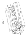
- Fig. 1 illustrates in perspective a multihead serial printer according to the first embodiment.
- Designated as 101 is a sheet of print paper, 102 a platen, 103a and 103b print heads, 104 an ink ribbon cartridge, 105a and 105b shift mechanisms for vertically moving the print heads 103a and 103b along the surface of the platen 102,106 and 107 guide shafts, and 108 a rack.
- the print heads 103a, 103b are arranged in a character-spacing direction, and can be independently shifted in a paper-feeding, or line-spacing, or column direction and moved in the character-spacing or line direction.
- Fig. 2 fragmentarily shows a mechanism for shifting the print head 103a in the column direction and moving the same in the line direction.
- the mechanism includes a shifting motor 109a for actuating the shift mechanism 105a to shift the print head 103a in the column direction, and a flat DC brushless motor 110a having a gear meshing with the rack 108, the motor 110a being attached to a carriage 111 a.
- the carriage 111 a is supported on the guide shafts 106, 107 for movement in the character-spacing direction.
- Operation of the multihead serial printer according to the first embodiment is as follows: When the flat DC brushless motor 110a is rotated, the carriage 111a is moved under a reactive force since a pinion mounted on a rotatable shaft of the motor is held in mesh with the rack 108. As the carriage 111 a is guided and supported by the guide shafts 106, 107, the carriage 111a a moves in a character-spacing or line direction. As the shifting motor 109a is rotated, the print head 108a is caused by the shift mechanism 105a to move in a paper-feeding or column direction along the surface of the platen 102. The print head 103a can thus be shifted in the column direction and moved in the line direction. When print wires are projected while the print head 103a is moved in the line direction, ink is transferred thereby from an ink ribbon of the ink ribbon cartridge 104 to form dots on the sheet 101.
- the print head 103b can also be shifted in the column direction and moved in the line direction in the same manner as described above. Since the print heads 103a, 103b are shifted and moved by the separate motors, they can be controlled independently of each other. This advantage will be described with reference to Figs. 3 and 4.
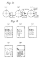
- Fig. 3 shows various shifted positions of the print heads 103a, 103b.
- Fig. 3(a) illustrates a position in which the print heads are horizontally aligned for printing one line.
- Fig. 3(b) shows a position in which one of the print heads is shifted for printing two lines.
- Fig. 3(c) is illustrative of a position in which one of the print heads is shifted by a pitch of 1/2 dot for high-density printing.
- the printing operation may be effected as shown in Fig. 4(c), employing movements similar to those in Fig. 4(a).
- the printing procedure of Fig. 4(b) is better inasmuch as two line feed operations for one line spacing are faster than one line feed operation for two line spacings.
- the print heads 103a, 103b are positioned in the high-density printing position illustrated in Fig. 3(c), and moved in the character-spacing directions indicated by the arrows from the mutually close positions (1) and (2) in Fig. 4(e) for printing. At this time, each print head is shifted in the column direction for an interval obtained by dividing one dot pitch of the print head by the number of print heads used (in the illustrated example, two print heads are employed, and they are shifted by 112 dot pitches).
- Fig. 5 is a perspective view of the shift mechanism which has side frames 112a, 113a and the shifting motor 109a, which are mounted on the carriage 111a.
- the side frames 112a, 113a have in their inner surfaces grooves 114a, 115b defined respectively therein and having a center of curvature equal to the center of the platen.
- a guide 116a has ridges 117a, 118a fitted respectively in the grooves 114a, 115a so that the guide 116a can be angularly moved along the surface of the platen.
- the guide 116a also has a substantially inverted U-shaped cam follower surface 119a in its central lower portion, and an eccentric cam 120a mounted on the rotatable shaft of the shifting motor 109a is held in contact with the cam follower surface 119a.
- the print head 103a isfixed to the guide 116a and sandwiched between the side frames 112a, 112b.
- the guide 116a is normally urged downwardly by a reset spring 121a.
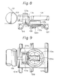
- Figs. 8 and 9 show a carriage drive mechanism.
- the flat DC brushless motor 110a is disposed below the carriage 111a a and has a shaft on which there is mounted a pinion 122a held in mesh with the rack 108.
- Fig. 10 illustrates the carriage drive mechanism in greater detail.
- the rotational angle of the flat DC brushless motor 110a is detected by a photosensor 123a.
- the rack 108 is fixed to a lower frame 124a.
- the print head 103a, the shifting motor 109a, the flat DC brushless motor 110a and the photosensor 123a, all mounted on the carriage 111a, are electrically connected to a control circuit, not shown, by a flexible cable 125a.
- the carriage drive mechanism operates by rotating the flat DC brushless motor 110a with electric power supplied through the flexible cable 125a, thus rotating the pinion 122a.
- the photosensor 123a issues a signal indicative of an angle of rotation of the motor 110a, and the carriage 111 a is moved under a reactive force from the rack 108.
- the shift mechanism shown in Figs. 5, 6, and 7, and the carriage drive mechanism illustrated in Figs. 8, 9, and 10 have been described as being associated with the print head 103a.
- the print head 103b is also associated with the same mechanisms.
- ink ribbon cartridges 104a, 104b may be used as shown in Fig. 11 in place of the ink ribbon cartridge 104, and may be mounted on carriages 111a, 111b, respectively.
- a righthand arm of the ink ribbon cartridge 104a and a lefthand arm of the ink ribbon cartridge 104b should be as thin as possible to position the print heads 103a, 103b closely together. This reduces distances which the print heads have to move in approaching the print-start positions in the print formats shown in Figs. 4(b) and (e).
- the self-propelled carriage drive mechanism with the drive motor mounted on the carriage is simpler in construction, the drive motor may be mounted on the frame, and the carriage may be moved by the drive motor through a belt or a wire.
- the print head may be moved perpendicularly to the carriage.
- the grooves 114a, 115a and the ridges 116a, 117a are straight in configuration.
- a space required therefor may be of substantially the same dimensions as those for the space for a single head, and the pair of guide shafts is sufficient.
- the print heads are only shifted in the paper-feeding direction, and there is no paper feeding operation which would feed the sheet in an unstable interval. Therefore, any positional error is small to maintain good printing quality.
- At least one of print heads comprises a pen head.
- Fig. 13 illustrates in perspective a multihead serial printer according to the second embodiment of the present invention.
- Designated as 201 is a sheet of print paper, 202 a platen around which the sheet 201 is wound to provide a print surface, and 203a, 203b guide shafts extending parallel to the platen 202, the platen 202 and the guide shafts 203a, 203b being supported at their ends by frames.
- 204, 205 are carriages slidably mounted on the guide shafts 203a, 203b, 206 an ordinary print head mounted on the carriage 204 and having dot-matrix wires, 207 an ink ribbon cartridge mounted on the carriage 204, 208 a pen head mounted on the carriage 205 and having a plurality of pens, 209 a vertical shift mechanism (described later) for moving the pen head 208 in a direction in which the sheet 201 is fed, i.e., in the column direction, and 210 a rack held in mesh with pinions on spacing motors mounted respectively on the carriages 204, 205.
- the carriages 204, 205 can therefore be selectively moved independently or together in the character-spacing direction.
- the vertical shift mechanism 209 for the pen head 208 will be described.
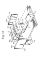
- Fig. 14 is an enlarged exploded perspective view of the vertical shift mechanism 209.
- the pens are designated as 211 and may comprise ball-point pens or ink pens.
- the pens 211 are horizontally supported by guides 212 so as to be directed toward the platen 202.
- the guides 212 are sandwiched by and between guides 213 having grooves 214a, 214b, having a center of curvature equal to the center of the platen 202.
- the guides 212 are fitted endwise in the grooves 214a, 214b for sliding movement therein. With the guides 212 thus slidably moved, the tip ends of the pens 211 can be moved along the surface of the platen 202 in the paper-feeding or column direction for a desired interval.
- Designated as 215 is a cam follower supporting thereon the guides 212 and urged by a reset spring 216 toward the carriage 205.
- An eccentric cam 217 is disposed in the cam follower 215 and rotatable by a drive motor 218. When the eccentric cam 217 is rotated by the drive motor 218, the cam follower 215 is moved up and down.
- An actuator 219 has one end engaging in slots 211 a in the pens 211 and is magnetically attracted by a magnet 220. The actuator 219 is moved under magnetic attraction of the magnet 220 to press the pens 211 toward the platen 202.
- the vertical shift mechanism 209 is thus constructed, and its operation will not be described as it is the same as the operation of the first embodiment described with reference to Figs. 6 and 7.
Landscapes
- Character Spaces And Line Spaces In Printers (AREA)
- Printers Characterized By Their Purpose (AREA)
Claims (3)
Applications Claiming Priority (6)
| Application Number | Priority Date | Filing Date | Title |
|---|---|---|---|
| JP23431183A JPS60127173A (ja) | 1983-12-14 | 1983-12-14 | マルチヘツドシリアルプリンタ |
| JP234311/83 | 1983-12-14 | ||
| JP58234331A JPH0825324B2 (ja) | 1983-12-14 | 1983-12-14 | マルチヘツドプリンタ |
| JP234331/83 | 1983-12-14 | ||
| JP8837684A JPS60232977A (ja) | 1984-05-04 | 1984-05-04 | プリンタプロツタ |
| JP88376/84 | 1984-05-04 |
Publications (3)
| Publication Number | Publication Date |
|---|---|
| EP0145025A2 EP0145025A2 (de) | 1985-06-19 |
| EP0145025A3 EP0145025A3 (en) | 1987-08-12 |
| EP0145025B1 true EP0145025B1 (de) | 1990-07-25 |
Family
ID=27305796
Family Applications (1)
| Application Number | Title | Priority Date | Filing Date |
|---|---|---|---|
| EP84115432A Expired - Lifetime EP0145025B1 (de) | 1983-12-14 | 1984-12-14 | Seriendrucker mit mehreren Schreibköpfen |
Country Status (2)
| Country | Link |
|---|---|
| EP (1) | EP0145025B1 (de) |
| DE (1) | DE3482822D1 (de) |
Cited By (1)
| Publication number | Priority date | Publication date | Assignee | Title |
|---|---|---|---|---|
| US7097278B1 (en) | 1997-02-20 | 2006-08-29 | Xaar Technology Limited | Printer and method of printing |
Families Citing this family (9)
| Publication number | Priority date | Publication date | Assignee | Title |
|---|---|---|---|---|
| US4687361A (en) * | 1985-03-07 | 1987-08-18 | Oki Electric Industry Co., Ltd. | Rack mount for a rack and pinion carriage moving mechanism |
| DE3635861A1 (de) * | 1986-10-22 | 1988-05-05 | Olympia Aeg | Aufzeichnungsvorrichtung fuer schreib- oder bueromaschinen aehnlicher bauart |
| FR2607073B1 (fr) * | 1986-11-24 | 1989-05-19 | Viaud Remi | Procede pour l'impression de documents recto-verso et imprimante utilisee pour sa mise en oeuvre |
| DE68916279T2 (de) * | 1988-03-02 | 1994-11-17 | Canon Kk | Registriervorrichtung mit einer Vielzahl von zu verkettenden Druckwagen. |
| JP2785031B2 (ja) * | 1988-03-02 | 1998-08-13 | キヤノン株式会社 | シリアルプリンタ |
| US4976556A (en) * | 1989-01-09 | 1990-12-11 | Smith Corona Corporation | Print carrier rack drive |
| JP3391924B2 (ja) * | 1995-01-31 | 2003-03-31 | キヤノン株式会社 | 画像記録装置 |
| DE60031213T2 (de) | 1999-09-03 | 2007-08-23 | Canon K.K. | Flüssigkeitsdruckkopf, Drucker, und Verfahren zum positionieren des Flüssigkeitsdruckkopfs im Drucker |
| US6984014B2 (en) * | 2002-01-24 | 2006-01-10 | Hewlett-Packard Development Company, L.P. | Inkjet printing system employing multiple inkjet printheads and method of performing a printing operation |
Family Cites Families (3)
| Publication number | Priority date | Publication date | Assignee | Title |
|---|---|---|---|---|
| DE2226394C3 (de) * | 1972-05-31 | 1980-12-04 | Robert Bosch Gmbh, 7000 Stuttgart | Schnelldrucker |
| FR2439675A1 (fr) * | 1978-10-26 | 1980-05-23 | Satas | Imprimante a tetes multiples |
| EP0082336B1 (de) * | 1981-12-21 | 1988-07-13 | International Business Machines Corporation | Drucken mit wählbarer Dichte mittels in einem festen räumlichen Verhältnis stehenden Punktmatrixdruckköpfen |
-
1984
- 1984-12-14 EP EP84115432A patent/EP0145025B1/de not_active Expired - Lifetime
- 1984-12-14 DE DE8484115432T patent/DE3482822D1/de not_active Expired - Fee Related
Non-Patent Citations (1)
| Title |
|---|
| IBM TECHNICAL DISCLOSURE BULLETIN, vol. 19, no. 9, Feb. 1977, pages 3335-3356 * |
Cited By (1)
| Publication number | Priority date | Publication date | Assignee | Title |
|---|---|---|---|---|
| US7097278B1 (en) | 1997-02-20 | 2006-08-29 | Xaar Technology Limited | Printer and method of printing |
Also Published As
| Publication number | Publication date |
|---|---|
| DE3482822D1 (de) | 1990-08-30 |
| EP0145025A2 (de) | 1985-06-19 |
| EP0145025A3 (en) | 1987-08-12 |
Similar Documents
| Publication | Publication Date | Title |
|---|---|---|
| US4576490A (en) | Multihead serial printer | |
| US4408907A (en) | Dot printing device for accounting, terminal, telewriting machine, and similar office machine | |
| US6113232A (en) | Stationary pen printer | |
| EP0145025B1 (de) | Seriendrucker mit mehreren Schreibköpfen | |
| EP0043275B1 (de) | Reihenschlagdrucker mit zwei Drucksystemen | |
| EP0027734A1 (de) | Punktmatrixdrucker | |
| US4661003A (en) | Bidirectional color printing apparatus | |
| EP0467424B1 (de) | Vorrichtung zur Handhabung von Aufzeichnungsträgern für einen kompakten Drucker mit einer Vielzahl auf einem hin und her bewegbaren Schlitten angeordneten Druckköpfen | |
| US4391540A (en) | Within-line color change printing | |
| JPH0530186B2 (de) | ||
| EP0082336B1 (de) | Drucken mit wählbarer Dichte mittels in einem festen räumlichen Verhältnis stehenden Punktmatrixdruckköpfen | |
| US4842427A (en) | Plotting mechanism mounted on a ribbon cassette for typewriters or office machines | |
| US4060162A (en) | Ribbon lift guide | |
| US3317017A (en) | Printer with rolling anvil member | |
| US4230938A (en) | Computer input/output device | |
| US4761665A (en) | High speed print/cartridge printer/feeder | |
| JPS60232977A (ja) | プリンタプロツタ | |
| WO1992018948A1 (en) | Dot-matrix printer | |
| JPS6021289A (ja) | 熱転写プリンタ | |
| JP2001260506A (ja) | 熱転写プリンタ | |
| JPS6342580B2 (de) | ||
| GB2161756A (en) | Ribbon feeding apparatus for printers | |
| JP2661673B2 (ja) | 画像形成装置 | |
| JP2847906B2 (ja) | 印字装置 | |
| JPS61143157A (ja) | ドツトマトリツクスシリアルプリンタ |
Legal Events
| Date | Code | Title | Description |
|---|---|---|---|
| PUAI | Public reference made under article 153(3) epc to a published international application that has entered the european phase |
Free format text: ORIGINAL CODE: 0009012 |
|
| AK | Designated contracting states |
Designated state(s): DE FR GB |
|
| PUAL | Search report despatched |
Free format text: ORIGINAL CODE: 0009013 |
|
| AK | Designated contracting states |
Kind code of ref document: A3 Designated state(s): DE FR GB |
|
| 17P | Request for examination filed |
Effective date: 19880129 |
|
| 17Q | First examination report despatched |
Effective date: 19881207 |
|
| GRAA | (expected) grant |
Free format text: ORIGINAL CODE: 0009210 |
|
| AK | Designated contracting states |
Kind code of ref document: B1 Designated state(s): DE FR GB |
|
| REF | Corresponds to: |
Ref document number: 3482822 Country of ref document: DE Date of ref document: 19900830 |
|
| ET | Fr: translation filed | ||
| PLBE | No opposition filed within time limit |
Free format text: ORIGINAL CODE: 0009261 |
|
| STAA | Information on the status of an ep patent application or granted ep patent |
Free format text: STATUS: NO OPPOSITION FILED WITHIN TIME LIMIT |
|
| 26N | No opposition filed | ||
| PGFP | Annual fee paid to national office [announced via postgrant information from national office to epo] |
Ref country code: FR Payment date: 19981209 Year of fee payment: 15 |
|
| PGFP | Annual fee paid to national office [announced via postgrant information from national office to epo] |
Ref country code: GB Payment date: 19981218 Year of fee payment: 15 |
|
| PGFP | Annual fee paid to national office [announced via postgrant information from national office to epo] |
Ref country code: DE Payment date: 19981221 Year of fee payment: 15 |
|
| PG25 | Lapsed in a contracting state [announced via postgrant information from national office to epo] |
Ref country code: GB Free format text: LAPSE BECAUSE OF NON-PAYMENT OF DUE FEES Effective date: 19991214 |
|
| GBPC | Gb: european patent ceased through non-payment of renewal fee |
Effective date: 19991214 |
|
| PG25 | Lapsed in a contracting state [announced via postgrant information from national office to epo] |
Ref country code: FR Free format text: LAPSE BECAUSE OF NON-PAYMENT OF DUE FEES Effective date: 20000831 |
|
| PG25 | Lapsed in a contracting state [announced via postgrant information from national office to epo] |
Ref country code: DE Free format text: LAPSE BECAUSE OF NON-PAYMENT OF DUE FEES Effective date: 20001003 |
|
| REG | Reference to a national code |
Ref country code: FR Ref legal event code: ST |