EP0144005B1 - Pneumatisches Schlagwerkzeug - Google Patents
Pneumatisches Schlagwerkzeug Download PDFInfo
- Publication number
- EP0144005B1 EP0144005B1 EP84113292A EP84113292A EP0144005B1 EP 0144005 B1 EP0144005 B1 EP 0144005B1 EP 84113292 A EP84113292 A EP 84113292A EP 84113292 A EP84113292 A EP 84113292A EP 0144005 B1 EP0144005 B1 EP 0144005B1
- Authority
- EP
- European Patent Office
- Prior art keywords
- piston
- face
- cylinder
- compressed air
- hammer
- Prior art date
- Legal status (The legal status is an assumption and is not a legal conclusion. Google has not performed a legal analysis and makes no representation as to the accuracy of the status listed.)
- Expired
Links
Images

Classifications
-
- A—HUMAN NECESSITIES
- A61—MEDICAL OR VETERINARY SCIENCE; HYGIENE
- A61B—DIAGNOSIS; SURGERY; IDENTIFICATION
- A61B17/00—Surgical instruments, devices or methods
- A61B17/16—Instruments for performing osteoclasis; Drills or chisels for bones; Trepans
- A61B17/1659—Surgical rasps, files, planes, or scrapers
-
- B—PERFORMING OPERATIONS; TRANSPORTING
- B25—HAND TOOLS; PORTABLE POWER-DRIVEN TOOLS; MANIPULATORS
- B25D—PERCUSSIVE TOOLS
- B25D9/00—Portable percussive tools with fluid-pressure drive, i.e. driven directly by fluids, e.g. having several percussive tool bits operated simultaneously
- B25D9/14—Control devices for the reciprocating piston
- B25D9/16—Valve arrangements therefor
- B25D9/20—Valve arrangements therefor involving a tubular-type slide valve
-
- B—PERFORMING OPERATIONS; TRANSPORTING
- B25—HAND TOOLS; PORTABLE POWER-DRIVEN TOOLS; MANIPULATORS
- B25D—PERCUSSIVE TOOLS
- B25D9/00—Portable percussive tools with fluid-pressure drive, i.e. driven directly by fluids, e.g. having several percussive tool bits operated simultaneously
- B25D9/14—Control devices for the reciprocating piston
- B25D9/26—Control devices for adjusting the stroke of the piston or the force or frequency of impact thereof
-
- A—HUMAN NECESSITIES
- A61—MEDICAL OR VETERINARY SCIENCE; HYGIENE
- A61B—DIAGNOSIS; SURGERY; IDENTIFICATION
- A61B17/00—Surgical instruments, devices or methods
- A61B2017/00535—Surgical instruments, devices or methods pneumatically or hydraulically operated
- A61B2017/00544—Surgical instruments, devices or methods pneumatically or hydraulically operated pneumatically
-
- A—HUMAN NECESSITIES
- A61—MEDICAL OR VETERINARY SCIENCE; HYGIENE
- A61B—DIAGNOSIS; SURGERY; IDENTIFICATION
- A61B17/00—Surgical instruments, devices or methods
- A61B17/56—Surgical instruments or methods for treatment of bones or joints; Devices specially adapted therefor
- A61B17/58—Surgical instruments or methods for treatment of bones or joints; Devices specially adapted therefor for osteosynthesis, e.g. bone plates, screws or setting implements
- A61B17/88—Osteosynthesis instruments; Methods or means for implanting or extracting internal or external fixation devices
- A61B17/92—Impactors or extractors, e.g. for removing intramedullary devices
- A61B2017/922—Devices for impaction, impact element
- A61B2017/924—Impact element driving means
-
- B—PERFORMING OPERATIONS; TRANSPORTING
- B25—HAND TOOLS; PORTABLE POWER-DRIVEN TOOLS; MANIPULATORS
- B25D—PERCUSSIVE TOOLS
- B25D2209/00—Details of portable percussive tools with fluid-pressure drive, i.e. driven directly by fluids, e.g. having several percussive tool bits operated simultaneously
- B25D2209/005—Details of portable percussive tools with fluid-pressure drive, i.e. driven directly by fluids, e.g. having several percussive tool bits operated simultaneously having a tubular-slide valve, which is coaxial with the piston
-
- B—PERFORMING OPERATIONS; TRANSPORTING
- B25—HAND TOOLS; PORTABLE POWER-DRIVEN TOOLS; MANIPULATORS
- B25D—PERCUSSIVE TOOLS
- B25D2250/00—General details of portable percussive tools; Components used in portable percussive tools
- B25D2250/171—Percussive pulling action of tools for extraction of elements
Definitions
- the present invention relates to a pneumatic percussion tool with a socket which is fixedly connected to a pneumatic cylinder for receiving a machining tool and with a piston which acts as a hammer and which has a first surface for the piston feed directed against the machining tool on a first surface which can be pressurized intermittently and the other side of which is designed as a hammer surface acting against the machining tool.
- the bone marrow cavity When artificial joints are inserted into a living organism, the bone marrow cavity is usually opened to anchor the artificial joint part in it.
- the firm connection between the bone and the anchor of the joint part protruding into the open medullary cavity is made by bone cement, which fills the gap between the anchor and the bone.
- the joint part anchor it is also known to design the joint part anchor as a blunt wedge with a small wedge angle and to machine out bearing surfaces for the wedge surfaces with a correspondingly small suit in the bone marrow cavity. In this case, the joint part is anchored cementlessly in the bone.
- the storage areas in the marrow cavity are worked out using profile rasps of different widths.
- the surgeon starts with the rasp of the smallest width and continues the machining process up to the preoperative, predetermined size on the basis of the x-ray image, which brings the bearing surface exactly in line with the wedge flanks on the joint part anchor.
- the bearing surfaces are worked out of the hard, cortical tubular bone after the relatively soft cancellous bone has already been removed.
- a rasp is driven into the bone by hand with a so-called slide hammer.
- the slide hammer has a rasp version at the end of a slide rod.
- a weight body is slidably mounted on the slide rod and is struck by the operator against a striking surface of the tool holder.
- percussion tools for chiselling and hammering are known in the art. If the rasps mentioned are driven with such devices in the medullary cavity of a bone, the rasps can no longer be removed from the medullary cavity, or can only be removed with difficulty, so that these striking tools cannot be used instead of the slide hammer mentioned.
- the present invention sets itself the task of improving a striking tool of a known type in such a way that it not only drives the machining tools mentioned precisely, but also that these tools can be easily pulled out of the bone marrow cavity at any time during the advance.
- this object is achieved in that there is a smaller second surface on the piston opposite to the first surface mentioned, which can be pressurized with compressed air intermittently for the piston return, and in that on the first side mentioned there is a second hammer surface which is at the end of the piston return on the facing cylinder surface.
- the rasp driving into the medullary cavity is subjected to a loose kick after each advancing blow, so that it is not positively and / or materially retained in the medullary cavity in any phase of the advance.
- the bone is treated more gently and at the same time the wedge surfaces can be worked out much more precisely.
- the resulting bone chips are better removed from the marrow cavity.
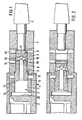
- the striking tool shown in the drawing has a pneumatic cylinder 1 consisting of the axially nested parts 2 and 3, the front end of part 3 being firmly connected to a tool holder 4 for a rasp 5.
- the cylinder 1 forms a cylinder space 6 axially adjoining the rasp 5, which has a section 7 with a larger and a section 8 with a smaller diameter.
- a piston 9 is axially displaceably mounted in the cylinder space 6 and can be displaced in a graduated manner according to the cylinder space, between a front (shown in FIG. 1) and a rear (shown in FIG. 3) end position.
- the piston 9 has a section 10 with a larger diameter and a section 11 with a smaller diameter corresponding to the cylinder space 6, whereby a shoulder surface 12 forms the transition. If the piston 9 is in the front end position shown in FIG. 1, the area of the shoulder surface 12 is surrounded by an annular chamber 13 of larger diameter, into which an air supply line 14 opens. At the grater-side end, the cylinder chamber 6 is continuously vented through a channel 15 connected to the outside atmosphere. A second ventilation channel 16 opens into the cylinder section 8 between the channel 15 and the annular chamber 16.
- the piston 9 has a compressed air on the back actable surface 17 which, together with the other piston surfaces facing away from the rasp 5, is substantially larger than the shoulder surface 12.
- a central blind bore 18 opens from the branches 19 into the piston jacket surface.
- the blind bores 18 and the adjacent part of the cylinder chamber 6 are vented through the mouth 19, whereas the pressure prevailing in the air supply line 14 acts on the shoulder surface 12 via the annular chamber 13.
- the piston 9 is driven backwards.
- the abrupt impact of the piston 9 (at the end of the advance) on the rasp 5 it experiences an elastic setback, this movement being supported by the pressure acting on the shoulder surface 12.
- the leading piston 9 suddenly hits the rasp 5 again and drives it further into the medullary cavity 5 of a bone.
- the elastic rebound and the air pressure acting on the shoulder surface 12 throw the piston 9 back until the surface 17 strikes against the rebound surface 20.
- the piston return is braked towards its end when compressed air flows again into the branch 19 in the annular chamber 13.
- the larger the shoulder surface 12 is selected (the diameter of the piston section 11 would have to be reduced accordingly), the faster the return movement of the piston 9 and the greater the recoil force that it generates when it hits the recoil surface 20.
- the check surface 20 is designed to be adjustable in the axial direction of the piston 9. This could increase or decrease the setback generated by the piston 9.
Landscapes
- Engineering & Computer Science (AREA)
- Health & Medical Sciences (AREA)
- Surgery (AREA)
- Physics & Mathematics (AREA)
- Mechanical Engineering (AREA)
- Fluid Mechanics (AREA)
- Life Sciences & Earth Sciences (AREA)
- Heart & Thoracic Surgery (AREA)
- Medical Informatics (AREA)
- Nuclear Medicine, Radiotherapy & Molecular Imaging (AREA)
- Oral & Maxillofacial Surgery (AREA)
- Dentistry (AREA)
- Biomedical Technology (AREA)
- Automation & Control Theory (AREA)
- Orthopedic Medicine & Surgery (AREA)
- Molecular Biology (AREA)
- Animal Behavior & Ethology (AREA)
- General Health & Medical Sciences (AREA)
- Public Health (AREA)
- Veterinary Medicine (AREA)
- Percussive Tools And Related Accessories (AREA)
- Surgical Instruments (AREA)
- Prostheses (AREA)
Description
- Die vorliegende Erfindung bezieht sich auf ein pneumatisches Schlagwerkzeug mit einer mit einem pneumatischen Zylinder fest verbundenen Fassung zur Aufnahme eines Bearbeitungswerkzeuges und mit einem als Hammer wirkenden Kolben, der auf einer ersten Seite für den gegen das Bearbeitungswerkzeug gerichteten Kolbenvorlauf eine intermittierend mit Druck beaufschlagbare erste Fläche aufweist und dessen andere Seite als gegen das Bearbeitungswerkzeug wirkende Hammerflächen ausgebildet ist.
- Beim Einsetzen künstlicher Gelenke in einen lebenden Organismus wird meistens die Knochenmarkhöhle geöffnet, um darin den künstlichen Gelenkteil zu verankern. Die feste Verbindung zwischen dem Knochen und dem in den geöffneten Markraum hineinragenden Anker des Gelenkteils erfolgt durch Knochenzement, der den Zwischenraum zwischen dem Anker und dem Knochen ausfüllt. Es ist indessen auch bekannt, den Gelenkteilanker als stumpfer Keil mit kleinem Keilwinkel auszubilden und in der Knochenmarkhöhle Lagerflächen für die Keilflächen mit entsprechend kleinem Anzug spanabhebend herauszuarbeiten. In diesem Falle wird das Gelenkteil mit Reibschluss im Knochen zementlos verankert. Das Herausarbeiten der Lagerflächen in der Markhöhle erfolgt mittels Profilraspeln unterschiedlicher Breite. Dabei beginnt der Operateur mit der Raspel kleinster Breite und setzt den Bearbeitungsvorgang bis zur präoperativ, anhand des Röntgenbildes vorbestimmten Grösse fort, welche die Lagerfläche masslich genau in Übereinstimmung mit den Keilflanken am Gelenkteilanker bringt. Die Lagerflächen werden aus dem harten, corticalen Röhrenknochen herausgearbeitet, nachdem bereits der relativ weiche Spongiosaknochen entfernt wurde.
- Für das Raspeln wird jeweils eine Raspel mit einem sogenannten Gleithammer von Hand in den Knochen hineingetrieben. Der Gleithammer weist am Ende einer Gleitstange eine Raspelfassung auf. Auf der Gleitstange ist ein Gewichtskörper verschiebbar gelagert, der durch den Operateur gegen eine Schlagfläche der Werkzeugfassung geschlagen wird.
- Der manuelle Vortrieb der Raspel schafft durch seine Ungenauigkeit im Markraum ausreichend Spiel, um das Raspelwerkzeug wieder aus den Knochen herausziehen zu können. Der Nachteil dieses Hammers besteht, nebst dem unerwünschten Spiel zwischen Keil und Lagerflächen, darin, dass er wenig wirksam ist und für die Preparierung einer einzigen Protheseauflage im Oberschenkelknochen bis zu mehreren hundert Einzelschlägen erfordert, was zeitraubend ist und den Operateur ermüdet. Zudem werden die einzelnen Schläge auf den Patienten übertragen.
- Weiter sind in der Technik Schlagwerzeuge zum Meisseln und Hämmern bekannt. Werden die erwähnten Raspeln mit solchen Geräten in der Markhöhle eines Knochens getrieben, lassen sich die Raspeln nach erfolgtem Eintrieb nicht mehr oder nur schwer aus der Markhöhle entfernen, so dass diese Schlagwerkzeuge nicht anstelle des erwähnten Gleithammers verwendbar sind.
- Die vorliegende Erfindung stellt sich die Aufgage, ein Schlagwerkzeug bekannter Art derart zu verbessern, dass es die erwähnten Bearbeitungswerkzeuge nicht nur genau vortreibt, sondern auch, dass diese Werkzeuge jederzeit während des Vortriebs leicht aus der Knochenmarkhöhle herausgezogen werden können.
- Erfindungsgemäss wird diese Aufgabe dadurch gelöst, dass am Kolben eine der erwähnten ersten Fläche entgegengerichtete, kleinere, für den Kolbenrücklauf intermittierend mit Druckluft beaufschlagbare zweite Fläche vorhanden ist und dass auf der erwähnten ersten Seite eine zweite Hammerfläche vorhanden ist, die am Ende des Kolbenrücklaufs auf die zugewandte Zylinderfläche auftrifft.
- Durch die Erfindung wird die in die Markhöhle eintreibende Raspel nach jedem vortreibenden Schlag mit einem lockeren Rückschlag beaufschlagt, so dass sie in keiner Phase des Vortriebs form- und/oder materialschlüssig in der Markhöhle festgehalten ist. Der Knochen wird schonender behandelt und gleichzeitig können die Keilflächen wesentlich genauer herausgearbeitet werden. Zudem werden die entstehenden Knochenspäne besser aus der Markhöhle ausgetragen.
- Anhand der beiliegenden schematischen Zeichnung wird die Erfindung beispielsweise erläutert. Es zeigen:
- Fig. 1 einen Längsschnitt durch ein Schlagwerkzeug, wobei sich der Kolben in der vorderen Endlage befindet, in der er einen Schlag auf die Raspel ausübt,
- Fig. 2 eine gleiche Darstellung wie Fig. 1, wobei der Kolben im Rücklauf mittlere Stellung einnimmt,
- Fig. 3 eine gleiche Darstellung wie Fig. 1, wobei der Kolben die hintere Endlage einnimmt und
- Fig. 4 eine gleiche Darstellung wie Fig. 1, wobei der Kolben im Vorlauf eine mittlere Stellung einnimmt.
- Das in der Zeichnung gezeigte Schlagwerkzeug weist einen pneumatischen Zylinder 1 bestehend aus den axial ineinandergesteckten Teilen 2 und 3 auf, wobei das vordere Ende des Teils 3 fest mit einer Werkzeugfassung 4 für eine Raspel 5 verbunden ist. Der Zylinder 1 bildet einen axial an die Raspel 5 anschliessenden Zylinderraum 6, der einen Abschnitt 7 mit grösserem und einen Abschnitt 8 mit kleinerem Durchmesser aufweist. Im Zylinderraum 6 ist axial verschiebbar ein Kolben 9 gelagert, der abgestuft entsprechend dem Zylinderraum, zwischen einer vorderen (in Fig. 1 gezeigten) in einer hinteren (in Fig. 3 gezeigten) Endlage verschiebbar ist. Der Kolben 9 weist entsprechend dem Zylinderraum 6 einen Abschnitt 10 grösseren und einen Abschnitt 11 kleineren Durchmessers auf, wodurch eine Schulterfläche 12 den Übergang bildet. Befindet sich der Kolben 9 in der in Fig. 1 gezeigten vorderen Endlage, so ist der Bereich der Schulterfläche 12 von einer Ringkammer 13 grösseren Durchmessers umgeben, in die eine Luftzuführleitung 14 mündet. Am raspelseitigen Ende ist der Zylinderraum 6 durch einen mit der Aussenatmosphäre verbundenen Kanal 15 dauernd entlüftet. Zwischen dem Kanal 15 und der Ringkammer 16 mündet in den Zylinderabschnitt 8 ein zweiter Entlüftungskanal 16.
- Der Kolben 9 weist rückseitig eine mit Druckluft beaufschlagbare Fläche 17 auf, welche zusammen mit den übrigen, der Raspel 5 abgewandten Kolbenflächen wesentlich grösser als die Schulterfläche 12 ist. In dieser Fläche 17 mündet eine zentrale Sackbohrung 18 von der Verzweigungen 19 in die Kolbenmantelfläche münden. In der vorderen, in Fig. 1 gezeigten Endlage des Kolbens 9 sind durch die Mündung 19 die Sackbohrungen 18 und der angrenzende Teil der Zylinderkammer 6 entlüftet, wogegen der in der Luftzuführleitung 14 herrschende Druck über die Ringkammer 13 auf die Schulterfläche 12 wirkt. Hierdurch wird der Kolben 9 nach rückwärts getrieben. Durch das schlagartige Auftreffen des Kolbens 9 (am Ende des Vorlaufs) auf die Raspel 5 erfährt er einen elastischen Rückschlag, wobei diese Bewegung durch den auf die Schulterfläche 12 wirkenden Druck unterstützt wird. Sobald die Verzweigung 19 in den Bereich der Ringkammer 13 gelangt (Fig. 2) strömt Druckluft in die Sackbohrung 18 und den anschliessenden Teil der Zylinderkammer, wodurch der Rücklauf des Kolbens 9 gebremst wird. Die Bremswirkung soll indessen (bedingt durch ein entsprechendes Verhältnis der einander entgegengerichtet wirksamen Kolbenfläche 12 und 17) so bemessen sein, dass der Kolben 9 mit der Fläche 17 auf die Rückschlagfläche 20 aufschlägt und der Raspel 5 einen dem Vortrieb entgegengesetzt gerichteten elastischen Rückschlag induziert. Der sich in der Sackbohrung 18 aufbauende Luftdruck (Fig. 3) lässt den Kolben 9 wieder gegen die Raspel 5 vorlaufen, wobei die Vortriebskraft zusammenfällt, sobald die Verzweigung 19 den Kanal 16 erreicht und die vortreibende Druckluft abgeblasen wird. Der vorlaufende Kolben 9 trifft wieder schlagartig auf die Raspel 5 auf und treibt diese weiter in die Markhöhle 5 eines Knochens vor. Der elastische Rückschlag und der auf die Schulterfläche 12 wirkende Luftdruck schleudern den Kolben 9 wieder zurück, bis die Fläche 17 gegen die Rückschlagfläche 20 aufschlägt. Der Kolbenrücklauf erfährt gegen sein Ende eine Bremsung, wenn erneut Druckluft auf der Ringkammer 13 in die Verzweigung 19 strömt. Je grösser die Schulterfläche 12 gewählt wird (wobei der Durchmesser des Kolbenabschnittes 11 entsprechend zu verkleinern wäre), umso schneller ist die Rücklaufbewegung des Kolbens 9 und umso grösser die Rückschlagkraft die er beim Auftreffen auf die Rückschlagfläche 20 erzeugt.
- Nach einem nicht dargestellten Ausführungsbeispiel kann vorgesehen sein, dass die Rückschlagfläche 20 in axialer Richtung zum Kolben 9 verstellbar ausgeführt ist. Dadurch könnte der vom Kolben 9 erzeugte Rückschlag vergrössert oder verkleinert werden.
Claims (3)
Priority Applications (1)
| Application Number | Priority Date | Filing Date | Title |
|---|---|---|---|
| AT84113292T ATE29106T1 (de) | 1983-12-01 | 1984-11-05 | Pneumatisches schlagwerkzeug. |
Applications Claiming Priority (2)
| Application Number | Priority Date | Filing Date | Title |
|---|---|---|---|
| CH6428/83 | 1983-12-01 | ||
| CH6428/83A CH661239A5 (de) | 1983-12-01 | 1983-12-01 | Pneumatisches schlagwerkzeug. |
Publications (2)
| Publication Number | Publication Date |
|---|---|
| EP0144005A1 EP0144005A1 (de) | 1985-06-12 |
| EP0144005B1 true EP0144005B1 (de) | 1987-08-26 |
Family
ID=4309484
Family Applications (1)
| Application Number | Title | Priority Date | Filing Date |
|---|---|---|---|
| EP84113292A Expired EP0144005B1 (de) | 1983-12-01 | 1984-11-05 | Pneumatisches Schlagwerkzeug |
Country Status (7)
| Country | Link |
|---|---|
| US (1) | US4651833A (de) |
| EP (1) | EP0144005B1 (de) |
| JP (1) | JPS60141481A (de) |
| AT (1) | ATE29106T1 (de) |
| CA (1) | CA1252676A (de) |
| CH (1) | CH661239A5 (de) |
| DE (1) | DE3465571D1 (de) |
Cited By (2)
| Publication number | Priority date | Publication date | Assignee | Title |
|---|---|---|---|---|
| DE3801676C1 (en) * | 1988-01-21 | 1989-07-06 | Aesculap Ag, 7200 Tuttlingen, De | Striking tool for surgical instruments |
| DE3801678C1 (en) * | 1988-01-21 | 1989-08-17 | Aesculap Ag, 7200 Tuttlingen, De | Surgical rasp instrument |
Families Citing this family (24)
| Publication number | Priority date | Publication date | Assignee | Title |
|---|---|---|---|---|
| EP0354943B1 (de) * | 1988-01-21 | 1993-12-29 | Aesculap Ag | Schlagwerkzeug für chirurgische instrumente |
| DE3802033C1 (en) * | 1988-01-25 | 1989-06-22 | Hans-Guenter Prof. Dr.-Ing. Appel | Pneumatic striking instrument for medical purposes |
| CH681362A5 (de) * | 1990-04-20 | 1993-03-15 | Integral Medizintechnik | |
| US5210918A (en) * | 1991-10-29 | 1993-05-18 | Wozniak Walter E | Pneumatic slide hammer |
| EP0617926B1 (de) * | 1993-03-30 | 1998-08-05 | Imt Integral Medizintechnik Ag | Pneumatisches Schlagwerkzeug |
| US5449363A (en) | 1994-05-06 | 1995-09-12 | Browne Medical Systems, Inc. | Endoscopic lithotripsy system |
| DE19624446C1 (de) | 1996-06-19 | 1998-03-26 | Ferton Holding | Chirurgisches Instrument zum mechanischen Entfernen von Knochenzement, sowie Verfahren zum Erzeugen von Stoßwellen |
| EP0925033B1 (de) | 1996-07-18 | 2004-02-25 | Implant Innovations, Inc. | Motorisch angetriebene osteotomiewerkzeuge zum verdichten von knochengewebe |
| DE19820506C1 (de) * | 1998-05-08 | 2000-01-05 | Eska Implants Gmbh & Co | Vorrichtung zur Präparation eines menschlichen Röhrenknochens für die Implantation eines Knochenimplantates sowie Verfahren zum Betreiben dieser Vorrichtung |
| USD492775S1 (en) | 2003-02-12 | 2004-07-06 | Kyphon Inc. | Impact handle for hand held surgical instruments |
| US6997269B1 (en) | 2003-03-26 | 2006-02-14 | Snap-On Incorporated | Attachment for impact hammer |
| BE1015812A3 (nl) * | 2003-12-09 | 2005-09-06 | Advanced Custom Made Implants | Rasp voor op maat gemaakte prothesen. |
| ES2360537T3 (es) * | 2005-05-17 | 2011-06-06 | Imt Integral Medizintechnik Ag | Herramienta de percusión, en particular para uso quirúrgico. |
| US7681658B2 (en) | 2007-11-06 | 2010-03-23 | Maurice DUVAL | Pneumatic impact tool |
| CN111267005A (zh) * | 2020-02-27 | 2020-06-12 | 广州力多机器人智能科技有限公司 | 除锈面积大的除锈机 |
| WO2022103835A1 (en) | 2020-11-10 | 2022-05-19 | Zimmer, Inc. | Bi-spring surgical impact tool |
| JP7602052B2 (ja) | 2021-01-21 | 2024-12-17 | ジンマー,インコーポレイティド | 線形電動外科用ハンマ衝撃工具 |
| CA3206985A1 (en) | 2021-01-29 | 2022-08-04 | Zimmer, Inc. | Rotary electric surgical hammer impact tool |
| WO2022165223A1 (en) | 2021-01-29 | 2022-08-04 | Zimmer, Inc. | Orthopedic impactor tool |
| AU2022212275B2 (en) | 2021-02-01 | 2024-07-25 | Zimmer, Inc. | Tri-roll thread electric surgical impact tool |
| CA3211071A1 (en) | 2021-02-26 | 2022-09-01 | Zimmer, Inc. | Bi-spring surgical hammer impact tools |
| DE102022116409A1 (de) * | 2022-06-30 | 2024-01-04 | Endocon Gmbh | Chirurgisches Instrument |
| US12390259B2 (en) | 2022-07-19 | 2025-08-19 | Zimmer, Inc. | Linear electric surgical hammer impact tool |
| US12533171B2 (en) | 2023-03-06 | 2026-01-27 | Zimmer, Inc. | Chuck system for a powered surgical impactor |
Family Cites Families (12)
| Publication number | Priority date | Publication date | Assignee | Title |
|---|---|---|---|---|
| US743389A (en) * | 1902-01-14 | 1903-11-03 | Charles Harris Johnson | Fluid-pressure-operated tool. |
| US904725A (en) * | 1906-12-20 | 1908-11-24 | Cleveland Pneumatic Tool Co | Impact-tool. |
| US1440082A (en) * | 1918-10-05 | 1922-12-26 | Babcock & Wilcox Co | Fluid-actuated hammer |
| US1703203A (en) * | 1927-06-04 | 1929-02-26 | Sullivan Machinery Co | Pressure-fluid motor |
| US2536595A (en) * | 1946-10-04 | 1951-01-02 | Independent Pneumatic Tool Co | Portable spin riveting tool |
| US2655921A (en) * | 1951-07-09 | 1953-10-20 | Edward J Haboush | Vibratory tool for operating bone sets, bone chisels, and bone nail drivers |
| US2725878A (en) * | 1954-09-20 | 1955-12-06 | Union Broach Co Inc | Surgical mallet structure |
| FR1348165A (fr) * | 1963-02-15 | 1964-01-04 | Outil à percussion | |
| US3572448A (en) * | 1969-03-24 | 1971-03-30 | Joseph Marcenuk | Pneumatic impact tool |
| US3655921A (en) * | 1970-03-30 | 1972-04-11 | Bell Telephone Labor Inc | Electronic route translator |
| US4298074A (en) * | 1976-08-09 | 1981-11-03 | American Safety Equipment Corporation | Surgical device using impulse motor |
| US4231434A (en) * | 1978-02-21 | 1980-11-04 | Justus Edgar J | Hydraulic impact device |
-
1983
- 1983-12-01 CH CH6428/83A patent/CH661239A5/de not_active IP Right Cessation
-
1984
- 1984-11-05 AT AT84113292T patent/ATE29106T1/de not_active IP Right Cessation
- 1984-11-05 DE DE8484113292T patent/DE3465571D1/de not_active Expired
- 1984-11-05 EP EP84113292A patent/EP0144005B1/de not_active Expired
- 1984-11-20 JP JP59245853A patent/JPS60141481A/ja active Pending
- 1984-11-27 CA CA000468645A patent/CA1252676A/en not_active Expired
- 1984-11-28 US US06/675,523 patent/US4651833A/en not_active Expired - Lifetime
Cited By (2)
| Publication number | Priority date | Publication date | Assignee | Title |
|---|---|---|---|---|
| DE3801676C1 (en) * | 1988-01-21 | 1989-07-06 | Aesculap Ag, 7200 Tuttlingen, De | Striking tool for surgical instruments |
| DE3801678C1 (en) * | 1988-01-21 | 1989-08-17 | Aesculap Ag, 7200 Tuttlingen, De | Surgical rasp instrument |
Also Published As
| Publication number | Publication date |
|---|---|
| EP0144005A1 (de) | 1985-06-12 |
| CA1252676A (en) | 1989-04-18 |
| US4651833A (en) | 1987-03-24 |
| DE3465571D1 (en) | 1987-10-01 |
| CH661239A5 (de) | 1987-07-15 |
| JPS60141481A (ja) | 1985-07-26 |
| ATE29106T1 (de) | 1987-09-15 |
Similar Documents
| Publication | Publication Date | Title |
|---|---|---|
| EP0144005B1 (de) | Pneumatisches Schlagwerkzeug | |
| EP0354943B1 (de) | Schlagwerkzeug für chirurgische instrumente | |
| DE69737509T2 (de) | Automatische schlagvorrichtung | |
| DE2527595C2 (de) | Umkehrbare Schlagvorrichtung zur Herstellung von Bohrlöchern durch Verdrängen und Verdichten von Erdreich | |
| DE2409206A1 (de) | Schlagbohrer | |
| DE2551303C3 (de) | Druckluftbetriebene Tiefloch-Schlagbohrmaschine | |
| DE3710162C1 (de) | Rammbohrgeraet mit beweglichem Meissel | |
| DE10001841A1 (de) | Schneidwerkzeughalter mit einer ausgesparten Nut zur Entfernung des Scheidwerkzeugs | |
| CH681362A5 (de) | ||
| DE2062690C2 (de) | Druckmittelbetriebener Versenkbohrhammer | |
| DE2540838C2 (de) | Elektropneumatischer Hammer | |
| DE19929183B4 (de) | Luftfederschlagwerk mit Hohl-Schlagkolben mit Leerlauföffnung | |
| DE3315132A1 (de) | Selbststeuernde umsteuerbare bohrramme | |
| DE3241746C2 (de) | ||
| DE60035732T2 (de) | Bohrhammer | |
| DE10106942B4 (de) | Pneumatisches Bodenstechwerkzeug mit beweglichem Meißelkopf | |
| DE102009038383B4 (de) | Rammbohrvorrichtung | |
| DE102014016154A1 (de) | Rammbohrvorrichtung | |
| DE3802033C1 (en) | Pneumatic striking instrument for medical purposes | |
| DE1283769B (de) | Schlaghammer | |
| DE2349296B2 (de) | Druckluft-Schlagmaschine | |
| DE2033694A1 (de) | Schlagausubende Druckluft Selbst gangseinnchtung | |
| DE69216607T2 (de) | Bodenverdrängungshammer mit beweglichem kopf | |
| EP0731248A1 (de) | Schlaggerät | |
| DE3316013A1 (de) | Bohrhammer mit einem pneumatischen betaetigten schlagkoerper |
Legal Events
| Date | Code | Title | Description |
|---|---|---|---|
| PUAI | Public reference made under article 153(3) epc to a published international application that has entered the european phase |
Free format text: ORIGINAL CODE: 0009012 |
|
| AK | Designated contracting states |
Designated state(s): AT BE DE FR GB IT LU NL SE |
|
| 17P | Request for examination filed |
Effective date: 19850401 |
|
| 17Q | First examination report despatched |
Effective date: 19860929 |
|
| GRAA | (expected) grant |
Free format text: ORIGINAL CODE: 0009210 |
|
| ITF | It: translation for a ep patent filed | ||
| AK | Designated contracting states |
Kind code of ref document: B1 Designated state(s): AT BE DE FR GB IT LU NL SE |
|
| REF | Corresponds to: |
Ref document number: 29106 Country of ref document: AT Date of ref document: 19870915 Kind code of ref document: T |
|
| REF | Corresponds to: |
Ref document number: 3465571 Country of ref document: DE Date of ref document: 19871001 |
|
| ET | Fr: translation filed | ||
| PLBE | No opposition filed within time limit |
Free format text: ORIGINAL CODE: 0009261 |
|
| STAA | Information on the status of an ep patent application or granted ep patent |
Free format text: STATUS: NO OPPOSITION FILED WITHIN TIME LIMIT |
|
| 26N | No opposition filed | ||
| ITTA | It: last paid annual fee | ||
| EPTA | Lu: last paid annual fee | ||
| REG | Reference to a national code |
Ref country code: FR Ref legal event code: TP |
|
| REG | Reference to a national code |
Ref country code: GB Ref legal event code: 732E |
|
| NLS | Nl: assignments of ep-patents |
Owner name: ARGOMEDICAL AG TE CHAM, ZWITSERLAND. |
|
| EAL | Se: european patent in force in sweden |
Ref document number: 84113292.1 |
|
| ITPR | It: changes in ownership of a european patent |
Owner name: CESSIONE;ARGOMEDICAL AG |
|
| PGFP | Annual fee paid to national office [announced via postgrant information from national office to epo] |
Ref country code: BE Payment date: 20001002 Year of fee payment: 17 |
|
| PGFP | Annual fee paid to national office [announced via postgrant information from national office to epo] |
Ref country code: GB Payment date: 20001026 Year of fee payment: 17 |
|
| PGFP | Annual fee paid to national office [announced via postgrant information from national office to epo] |
Ref country code: LU Payment date: 20001114 Year of fee payment: 17 |
|
| PGFP | Annual fee paid to national office [announced via postgrant information from national office to epo] |
Ref country code: SE Payment date: 20001116 Year of fee payment: 17 |
|
| PGFP | Annual fee paid to national office [announced via postgrant information from national office to epo] |
Ref country code: NL Payment date: 20001130 Year of fee payment: 17 |
|
| PGFP | Annual fee paid to national office [announced via postgrant information from national office to epo] |
Ref country code: FR Payment date: 20010928 Year of fee payment: 18 |
|
| PG25 | Lapsed in a contracting state [announced via postgrant information from national office to epo] |
Ref country code: LU Free format text: LAPSE BECAUSE OF NON-PAYMENT OF DUE FEES Effective date: 20011105 Ref country code: GB Free format text: LAPSE BECAUSE OF NON-PAYMENT OF DUE FEES Effective date: 20011105 |
|
| PG25 | Lapsed in a contracting state [announced via postgrant information from national office to epo] |
Ref country code: SE Free format text: LAPSE BECAUSE OF NON-PAYMENT OF DUE FEES Effective date: 20011106 |
|
| PG25 | Lapsed in a contracting state [announced via postgrant information from national office to epo] |
Ref country code: BE Free format text: LAPSE BECAUSE OF NON-PAYMENT OF DUE FEES Effective date: 20011130 |
|
| REG | Reference to a national code |
Ref country code: GB Ref legal event code: IF02 |
|
| BERE | Be: lapsed |
Owner name: ARGOMEDICAL A.G. Effective date: 20011130 |
|
| PG25 | Lapsed in a contracting state [announced via postgrant information from national office to epo] |
Ref country code: NL Free format text: LAPSE BECAUSE OF NON-PAYMENT OF DUE FEES Effective date: 20020601 |
|
| GBPC | Gb: european patent ceased through non-payment of renewal fee |
Effective date: 20011105 |
|
| EUG | Se: european patent has lapsed |
Ref document number: 84113292.1 |
|
| NLV4 | Nl: lapsed or anulled due to non-payment of the annual fee |
Effective date: 20020601 |
|
| PGFP | Annual fee paid to national office [announced via postgrant information from national office to epo] |
Ref country code: AT Payment date: 20030422 Year of fee payment: 19 |
|
| PGFP | Annual fee paid to national office [announced via postgrant information from national office to epo] |
Ref country code: DE Payment date: 20030429 Year of fee payment: 19 |
|
| PG25 | Lapsed in a contracting state [announced via postgrant information from national office to epo] |
Ref country code: FR Free format text: LAPSE BECAUSE OF NON-PAYMENT OF DUE FEES Effective date: 20030731 |
|
| REG | Reference to a national code |
Ref country code: FR Ref legal event code: ST |
|
| PG25 | Lapsed in a contracting state [announced via postgrant information from national office to epo] |
Ref country code: AT Free format text: LAPSE BECAUSE OF NON-PAYMENT OF DUE FEES Effective date: 20031105 |
|
| PG25 | Lapsed in a contracting state [announced via postgrant information from national office to epo] |
Ref country code: DE Free format text: LAPSE BECAUSE OF NON-PAYMENT OF DUE FEES Effective date: 20040602 |