EP0143930A2 - Method and apparatus for manufacturing brushes - Google Patents
Method and apparatus for manufacturing brushes Download PDFInfo
- Publication number
- EP0143930A2 EP0143930A2 EP84111396A EP84111396A EP0143930A2 EP 0143930 A2 EP0143930 A2 EP 0143930A2 EP 84111396 A EP84111396 A EP 84111396A EP 84111396 A EP84111396 A EP 84111396A EP 0143930 A2 EP0143930 A2 EP 0143930A2
- Authority
- EP
- European Patent Office
- Prior art keywords
- bristle
- bundle
- gripper
- machine according
- separating device
- Prior art date
- Legal status (The legal status is an assumption and is not a legal conclusion. Google has not performed a legal analysis and makes no representation as to the accuracy of the status listed.)
- Granted
Links
Images


Classifications
-
- A—HUMAN NECESSITIES
- A46—BRUSHWARE
- A46D—MANUFACTURE OF BRUSHES
- A46D3/00—Preparing, i.e. Manufacturing brush bodies
- A46D3/08—Parts of brush-making machines
- A46D3/082—Magazines for bristles; Feeding bristles to magazines; Knot picking
Definitions
- the invention relates to a method for producing brushes, in which bristle bundles enclosed by a covering, packaging or the like are brought into the vicinity of a bristle supply and are there fed to the bristle supply after removal of their packaging, covering or the like.
- a knife for separating the sheathing.
- Such a knife can be guided radially and / or in the longitudinal direction through the casing.
- the disadvantages here are that damage to the bristles cannot be ruled out by the knife and that the bristles can also be pushed out of the bristle supply by the knife, which can lead to malfunctions.
- such knives become dull over time and have to be replaced.
- there is also the fact that such a blunt knife can also cause malfunctions.
- additional devices are required to remove the separated coverings, so that a total of one increased effort is given.
- the object of the present invention is to provide a method of the type mentioned at the outset, by means of which a trouble-free separation of sheaths from the bristles therein is possible even over a longer period.
- the coated bristle bundle is grasped on its covering and this is removed in sections, after which the exposed bundle section is gripped and the bristle bundle and the covering are separated from one another.
- the bundle of bristles is held alternately, preferably overlapping in time, when the sheath is removed. As a result, the bundle of bristles is held securely during the entire separation process.
- the invention also relates to a brush production machine with a device for supplying bristles to a tamping device or the like, a separating device for removing an envelope or the like initially encasing the individual bristle bundles and a subsequent transfer device for the bristles or the bristle supply are provided.
- Such a brush manufacturing machine is according to the invention in particular characterized in that the Separating device has a gripping device with at least one holding and pulling-off gripper for gripping the covered bristle bundle and for at least partially pulling off the covering and at least one removal gripper or the like for gripping the free bundle section and for removing or transporting the bundle.
- the covering is pulled off somewhat in some areas and the bundle, which is then partially exposed, is gripped by the removal gripper and pulled out of the covering. Mechanical removal of the casing is achieved. Because there are practically no wearing parts, such a separating device is also largely maintenance-free.
- the grippers expediently each have at least two gripping jaws or the like which can be moved approximately radially to the bristle bundle, with gripping surfaces which are approximately matched to the outline shape of the bristle bundle, in particular approximately semicircular.
- the bundle of bristles is thereby tightly encompassed during the separation process and also for further transport, so that the bundle of bristles is held together without a covering.
- the holding and pulling gripper can be displaced in relation to the bristle bundle in the longitudinal direction thereof by part of the bundle length.
- the covering can thereby be gripped and pulled back somewhat by the displacement movement, so that one end of the bristle bundle becomes free.
- the removal gripper is expediently also approximately coaxial to the bristle bundle and additionally preferably transversely thereto, e.g. B. to a bristle magazine, movable.
- the removal gripper can grip the exposed bristle bundle and then pull it out of the casing and, if necessary, towards a bristle magazine or the like move.
- the bristle bundles are mounted approximately vertically in the region of the separating device, the gripping and pulling gripper engaging at the upper end or the removal gripper being arranged such that it can be fed from above. In this vertical position, the covering can be pulled off, a support for the bristles being formed on the underside by the support.
- a pressure application device is provided in the bristle magazine, which has pressure elements acting alternately on the bristle supply, the greatest distance between these pressure elements corresponding at least approximately to the cross-section of a bundle of bristles supplied by the removal gripper. The bristle bundles separated from the covering can thus be introduced into the bristle stock without the bristle stock already in the magazine having to be changed, in particular with regard to the pressurization.
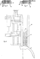
- a separating device 1 shown in FIG. 1 is part of a brush manufacturing machine, in which in particular bristles 3 initially located in a covering 2 are fed to a brush tamping machine, of which only the so-called circular arc divider 4 can be seen in FIGS. 1, 8 and 11.
- the separating device 1 essentially has a gripping device designated as 5.
- a holding and pulling gripper 6 is provided for gripping the covered bristle bundle 8, as shown in FIG. 1, and also for at least partially pulling off the covering 2, as can be seen in FIG. 2.
- the gripping device 5 also has a removal gripper 7, with which the free bundle section 9 can be gripped and pulled out of the casing 2.
- the bristle bundle 8 pulled out of the casing 2 is transported with the aid of the removal gripper 7 to a bristle supply 11 located in a magazine 10.
- the grippers 6 and 7 each have two gripping jaws 12, 13 in the exemplary embodiment, which have approximately adapted to the outline shape of the bristle bundle 8, in particular approximately semicircular gripping surfaces 14, as can be clearly seen in FIGS. 9 to 11.
- the holding and pulling gripper 6 is accommodated in a lifting frame 15, which overall can be displaced in height relative to the bristle bundle 8 located in the separating device 1 according to the arrow Pf 1.
- Pneumatic lifting drives 16 in particular are provided both for adjusting the gripping jaws 12 and 13 and for adjusting the height of the lifting frame 15.
- a bristle bundle 8 located in the separating device 1 is vertically open with respect to its longitudinal extent a support 17 is mounted, which in the exemplary embodiment is part of the bottom of a feed device 18 (cf. FIGS. 9 and 10).
- the sheathing 2 is now separated from a bundle of bristles 8 in that the coated bundle of bristles 8 is first gripped by the gripping jaws 12 of the holding and pulling gripper 6 at the upper end region, as can be clearly seen in FIG. 1.
- the lifting drive 16 for the lifting frame 15 By actuating the lifting drive 16 for the lifting frame 15, the holding and pulling gripper 6 is moved somewhat downward relative to the bristle bundle 8, the covering 2 being correspondingly stripped off.
- the lifting movement is dimensioned such that the upper bundle section 9, which is free of the covering 2, grips the removal gripper securely
- the lifting movement of the holding and pulling-off gripper 6 could be provided such that the covering 2 is stripped off over approximately half the bristle length.
- the removal gripper 7 in its up position in FIG. 1 is then moved to the bristle bundle 8 until its gripping jaws 13 are located to the side of the free bundle section 9. Then the bristle bundle 8 is gripped at its free bundle section 9 by closing the gripping jaws 13 (see FIG. 2) and pulled out of the casing 2 by raising the removal gripper 7.
- the holding and pulling gripper 6 remains approximately in its closed position during this separation process, but its gripping jaws 12 can yield somewhat radially, which can be achieved by removing the pressure from the lifting cylinders 16.
- the covering 2 is thus stripped off on the gripping jaws 12 without a greater pull-out resistance being present.
- the bristle bundle 8 is held alternately, preferably overlapping in time, by the grippers 6 and 7, so that the bristle bundle 8 is held securely in each phase of the separation.
- the removal gripper 7 is also horizontally displaceable, the horizontal guide 19 leading to the magazine 10 in the exemplary embodiment.
- a bristle bundle held by the gripping jaws 13 can thereby be transported laterally from the area of the separating device 1 into the area of the magazine 10.
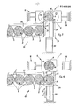
- the bristle magazine 10 has a pressurizing device with pressure elements 20, 21 which act alternately on the bristle supply 11. This causes an approximately constant supply pressure to the circular arc divider 4.
- the bristle bundle 8 is inserted into the magazine 10 between these pressure elements 20, 21, as is shown in FIG. 4. After the bristle bundle 8 has been deposited, it is acted upon and held on the back by the fork-shaped pressure element 20 (FIG. 5). Subsequently, as shown in FIG.
- the finger-shaped pressure element 21 can be pulled out of the bristle supply and then takes over the loading of the bristle supply instead of the fork-shaped pressure element 20.
- the fork-shaped pressure element 20 can then be moved back to a position (FIGS. 7 and 1) until the space between the pressure elements 20 and 21 is sufficient to accommodate the next bundle of bristles 8 separated from the sheath 2.
- FIG. 8 shows a top view of the arrangement of the pressure elements 20, 21 in the magazine 10, the discharge end of which opens in the region of the circular-arc compartment 4. It can also be clearly seen here that the pressure elements 20, 21 can be displaced both in the longitudinal direction of the magazine 10 and in the disengagement and engagement position.
- Fig. 11 shows a separation device 1 in supervision with an associated double magazine 10 a, in which, for example, bristles with different colors are entered.
- the removal gripper 7 is arranged so as to be displaceable transversely to the longitudinal extent of the magazine 10 a in accordance with the distance between these magazine channels.
- the lifting cylinder 22 is provided as the drive, while a further lifting cylinder 23 is provided for moving the removal gripper 7 from the separating device to the magazine 10 a.
- the holding and pulling gripper 6 lying below the removal gripper 7 is not visible in this illustration.
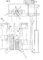
- the feed device shown in FIGS. 9 and 10 serves to feed the coated or coated bristle bundles 8 to the separating device 1. It has a separating device 24 with a combined blocking and transport slide 25 at its feed end. With the separating device 24, the bristle bundles 8 arriving one after the other via a guide channel 26 can be fed one after the other to the separating device 1.
- the locking and transport slide 25 is approximately angular in shape with a locking side 27 and a feed side 28. If the slide 25 is in the release position shown in FIG. 9, the bristle bundles located in the guide channel 26, which preferably runs at an angle, can slip, the foremost one resting against a stop 29.
- the slide 25 By moving the slide 25 transversely, for which a lifting cylinder 30 is provided here, the slide 25 moves into the blocking position shown in FIG. 8, whereby it transports the bundle of bristles 8 resting against the stop 29 into the separating device 1. After the slide has been pulled back, the gripping jaws 12 of the holding and pulling-off gripper 6 shown here can grip the bristle bundle 8 or its sheath 2.
- the stripped sheath 2 could be removed by compressed air.
- the magazines 10, 10 a often have comparatively narrow receiving channels for the bristle supply 11, the width of these channels being smaller than the diameter of the approximately round bristle bundles 8.
- the bristle bundles are adapted to the shape of the bristle receptacle, in particular to the width of the magazine receptacle channels, during and / or after removal of the sheath 2.
- the clear receiving cross-section of the gripping jaws 13 of the removal gripper 7 in the closed position z. B. be rectangular, the narrow sides at most corresponding to the width of a magazine receiving channel.
- the bristle bundle 8 could also be gradually deformed from its round cross-sectional shape into a cross-sectional shape suitable for a subsequent magazine.
- the receiving cross section of the gripping jaws 12 of the holding and pulling gripper 6 can already have an intermediate shape between the round cross section and the intended delivery cross section of the bristle bundle, and the receiving cross section of the removal gripper jaws 13 can correspond to the final, intended delivery cross section of the bristle bundles 8.
- the separating borehole direction 1 can also be designed for horizontal storage of the bristle bundles 8, preferably with a one-sided, end-face stop.
- the design with gripping jaws fixed on one side is also particularly advantageous. It should also be mentioned that the gripping jaws 12 are fixed in the pulling direction and the end stop or the base 17 can be movable relative to it for the partial removal of the casing 2.
- the separating device 1 according to the invention can also be used separately without a feed connection to a bristle storage magazine or, if appropriate, in connection with a material dressing device.
- the separating device 1 according to the invention also in connection with the respectively adjacent devices 18 and 10, has the essential advantage that the transport, the respective transfers and the separation of the casing 2 with comparatively simple means and at the same time high operational reliability even over longer production sections without problems can expire. This is also a prerequisite for the planned, largely largely automatic overall production process.
- a double magazine 10 a (Fig.
- associated separating device 1 is expediently also provided a double feed device 18 a for bristle bundles 8, as shown in FIG. 12.
- bristle bundles 8 containing alternating or optionally different bristles can be fed to the separating device 1.
- the bristles held by the removal gripper 7 are fed to one of the magazine channels 31 or 31 a, depending on the type.
- the bristles can e.g. B. differ in terms of color, bristle length, thickness, material, etc.
- the feed device 18 a and the magazine are designed for two different types of bristles. If necessary, these devices could also be set up for more than two types of bristle. Despite this processing of several types of bristle, it is advantageous to use only one separating device 1. The mechanical effort is therefore comparatively low overall even when processing several different types of bristle.
- two feed channels 32 coming from bristle bundle magazines can be seen which are connected to the separating device 24.
- the feed channels 32 and the connecting channel 34 can be arranged obliquely as slides.
Landscapes
- Engineering & Computer Science (AREA)
- Manufacturing & Machinery (AREA)
- Brushes (AREA)
Abstract
Eine zu einer Bürstenherstellungsmaschine gehörende Trennvorrichtung (1) dient zum Entfernen einer Umhüllung (2) von Borstenbündeln (8). Dazu dient eine Greifeinrichtung (5) mit einem Halte- und Abziehgreifer (6) einerseits und einem Entnahmegreifer (7) andererseits. Mit dem Halte- und Abziehgreifer (6) wird zunächst die Umhüllung (2) erfaßt und etwas relativ zum Borstenbündel (8) längsverschoben, so daß ein umhüllungsfreier Bündelabschnitt vorhanden ist, an dem der Entnahmegreifer (7) angreifen kann. Dieser zieht dann das Borstenbündel (8) aus der etwas zurückgestrieften Umhüllung (2) heraus und kann es dann zu einem nachgeschalteten Magazin (10) weitertransportieren.A separating device (1) belonging to a brush manufacturing machine is used to remove an envelope (2) from bristle bundles (8). For this purpose, a gripping device (5) with a holding and pulling gripper (6) on the one hand and a removal gripper (7) on the other hand. With the holding and pulling gripper (6), the sheath (2) is first gripped and moved longitudinally somewhat relative to the bristle bundle (8), so that a sheath-free bundle section is present, on which the removal gripper (7) can engage. The latter then pulls the bristle bundle (8) out of the somewhat recessed envelope (2) and can then transport it further to a downstream magazine (10).
Description
Die Erfindung betrifft ein Verfahren zum Herstellen von Bürsten, bei dem zunächst von einer Umhüllung, Verpakkung od. dgl. umschlossene Borstenbündel in die Nähe eines Borstenvorrates gebracht und dort nach dem Entfernen ihrer Verpackung, Ummantelung od. dgl. dem Borstenvorrat zugeführt werden. Zum Entfernen der Umhüllung von Borstenbündeln ist es bereits bekannt, Messer zum Auftrennen der Umhüllung vorzusehen. Ein solches Messer kann dabei radial und/ oder in Längsrichtung durch die Umhüllung geführt werden. Nachteilig ist dabei, daß Beschädigungen der Borsten durch das Messer nicht auszuschließen sind und daß auch Borsten durch das Messer aus dem Borstenvorrat herausgeschoben werden können, was zu Betriebsstör ungen führen kann. Außerdem werden solche Messer mit der Zeit stumpf und müssen ausgewechselt werden. Neben der dazu notwendigen Betriebsunterbrechung kommt noch hinzu, daß durch ein solches stumpfes Messer ebenfalls Betriebsstörungen auftreten können. Schließlich sind zum Entfernen der aufgetrennten Umhüllungen noch zusätzliche Einrichtungen erforderlich, so daß insgesamt auch ein erhöhter Aufwand gegeben ist.The invention relates to a method for producing brushes, in which bristle bundles enclosed by a covering, packaging or the like are brought into the vicinity of a bristle supply and are there fed to the bristle supply after removal of their packaging, covering or the like. To remove the sheathing from bundles of bristles, it is already known to provide knives for separating the sheathing. Such a knife can be guided radially and / or in the longitudinal direction through the casing. The disadvantages here are that damage to the bristles cannot be ruled out by the knife and that the bristles can also be pushed out of the bristle supply by the knife, which can lead to malfunctions. In addition, such knives become dull over time and have to be replaced. In addition to the necessary interruption to operation, there is also the fact that such a blunt knife can also cause malfunctions. Finally, additional devices are required to remove the separated coverings, so that a total of one increased effort is given.
Aufgabe der vorliegenden Erfindung ist es, ein Verfahren der eingangs erwähnten Art zu schaffen, durch das auch über einen längeren Zeitraum ein störungsfreies Trennen von Umhüllungen von den darin befindlichen Borsten möglich ist.The object of the present invention is to provide a method of the type mentioned at the outset, by means of which a trouble-free separation of sheaths from the bristles therein is possible even over a longer period.
Zur Lösung dieser Aufgabe wird erfindungsgemäß insbesondere vorgeschlagen, daß das umhüllte Borstenbündel an seiner Umhüllung erfaßt und diese abschnittweise entfernt wird, wobei anschließend der freiliegende Bündelabschnitt ergriffen und das Borstenbündel und die Umhüllung voneinander getrennt werden.To achieve this object, it is proposed according to the invention in particular that the coated bristle bundle is grasped on its covering and this is removed in sections, after which the exposed bundle section is gripped and the bristle bundle and the covering are separated from one another.
Einerseits werden dadurch Beschädigungen der innerhalb der Umhüllung befindlichen Borsten praktisch ausgeschlossen und außerdem ist auch ein störungsfreier Betrieb über einen längeren Zeitraum möglich, da praktisch keine Verschleißteile bei diesem Verfahren verwendet werden.On the one hand, damage to the bristles located within the covering is practically excluded and, moreover, trouble-free operation over a longer period of time is possible, since practically no wearing parts are used in this method.
Besonders vorteilhaft ist es, wenn das Borstenbündel beim Entfernen der Umhüllung wechselweise, vorzugsweise zeitlich überschneidend gehalten wird. Dadurch ist das Borstenbündel während des gesamten Trennvorganges sicher gehalten.It is particularly advantageous if the bundle of bristles is held alternately, preferably overlapping in time, when the sheath is removed. As a result, the bundle of bristles is held securely during the entire separation process.
Die Erfindung betrifft auch eine Bürstenherstellungsmaschine mit einer Einrichtung zum Zuführen von Borsten zu einer Stopfeinrichtung od. dgl., wobei eine Trennvorrichtung zum Entfernen einer die einzelnen Borstenbündel zunächst ummantelnden Umhüllung od. dgl. sowie eine sich daran anschließende Weitergabeeinrichtung für die Borsten bzw. den Borstenvorrat vorgesehen sind.The invention also relates to a brush production machine with a device for supplying bristles to a tamping device or the like, a separating device for removing an envelope or the like initially encasing the individual bristle bundles and a subsequent transfer device for the bristles or the bristle supply are provided.
Eine solche Bürstenherstellungsmaschine ist erfindungsgemäß insbesondere dadurch gekennzeic hnet, daß die Trennvorrichtung ei ne Greifeinrichtung mit wenigstens einem Halte- und Abziehgreifer zum Erfassen des umhüllten Borstenbündels sowie zum zumindest teilweisen Abziehen der Umhüllung und wenigstens einen Entnahmegreifer od. dgl. zum Erfassen des freien Bündelabschnittes sowie zum Entfernen bzw. Weitertransportieren des Bündels aufweist . Mittels einer solchen Trennvorrichtung wird die Umhüllung bereichsweise etwas abgezogen und das dann teilweise freiliegende Bündel durch den Entnahmegreifer erfaßt und aus der Umhüllung gezogen. Man erreicht ein mechanisches Abziehen der Umhüllung. Dadurch, daß praktisch keine Verschleißteile vorhanden sind, ist eine solche Trennvorrichtung auch weitgehend wartungsfrei.Such a brush manufacturing machine is according to the invention in particular characterized in that the Separating device has a gripping device with at least one holding and pulling-off gripper for gripping the covered bristle bundle and for at least partially pulling off the covering and at least one removal gripper or the like for gripping the free bundle section and for removing or transporting the bundle. By means of such a separating device, the covering is pulled off somewhat in some areas and the bundle, which is then partially exposed, is gripped by the removal gripper and pulled out of the covering. Mechanical removal of the casing is achieved. Because there are practically no wearing parts, such a separating device is also largely maintenance-free.
Zweckmäßigerweise weisen die Greifer jeweils mindestens zwei etwa radial zum Borstenbündel bewegbare Greifbacken od. dgl. mit an die Umrißform des Borstenbündels etwa angepaßten, insbesondere etwa halbkreisförmigen Greifflächen auf. Das Borstenbündel ist dadurch während des Trennvorganges und auch zum Weitertransportieren jeweils dicht umgriffen, so daß das Borstenbü ndel auch ohne Umhüllung zusammengehalten ist.The grippers expediently each have at least two gripping jaws or the like which can be moved approximately radially to the bristle bundle, with gripping surfaces which are approximately matched to the outline shape of the bristle bundle, in particular approximately semicircular. The bundle of bristles is thereby tightly encompassed during the separation process and also for further transport, so that the bundle of bristles is held together without a covering.
Nach einer Weiterbildung der Erfindung ist vorgesehen, daß der Halte- und Abziehgreifer relativ zum Borstenbündel in dessen Längsrichtung um einen Teil der Bündellänge verschiebbar ist. Die Umhüllung kann dadurch ergriffen und durch die Verschiebebewegung etwas zurückgestreift werden, so daß ein Borstenbündel-Ende frei wird. Zweckmäßigerweise ist auch der Entnahmegreifer etwa koaxial zum Borstenbündel sowie zusätzlich vorzugsweise quer dazu, z. B. zu einem Borstenmagazin, bewegbar. Der Entnahmegreifer kann an dem freiliegenden Borstenbündel angreifen und dieses dann aus der Umhüllung herausziehen und gegebenenfalls zu einem Borstenmagazin od. dgl. hin bewegen.According to a development of the invention, it is provided that the holding and pulling gripper can be displaced in relation to the bristle bundle in the longitudinal direction thereof by part of the bundle length. The covering can thereby be gripped and pulled back somewhat by the displacement movement, so that one end of the bristle bundle becomes free. The removal gripper is expediently also approximately coaxial to the bristle bundle and additionally preferably transversely thereto, e.g. B. to a bristle magazine, movable. The removal gripper can grip the exposed bristle bundle and then pull it out of the casing and, if necessary, towards a bristle magazine or the like move.
Gegebenenfalls sind die Borstenbündel im Bereich der Trennvorrichtung etwa vertikal gelagert, wobei der Halte-und Abziehgreifer am oberen Ende angreift bzw. der Entnahmegreifer von oben her zuführbar angeordnet ist. In dieser vertikalen Lage kann die Umhüllung nach oben abgezogen werden, wobei unterseitig durch die Unterstützung ein Gegenlager für die Borsten gebildet ist. Eine weitere Ausgestaltung der Erfindung sieht vor, daß bei dem Borstenmagazin eine Druckbeaufschlagungs-Vorrichtung vorgesehen ist, die den Borstenvorrat wechselweise beaufschlagende Druckelemente hat, wobei der größte Abstand dieser Druckelemente voneinander mindestens etwa dem Querschnitt eines durch den Entnahmegreifer zugeförderten Borstenbündels entspricht. Die von der Umhüllung getrennten Borstenbündel können so in den Borstenvorrat eingeführt werden, ohne daß der bereits im Magazin befindliche Borstenvo rrat dabei, insbesondere hinsichtlich der Druckbeaufschlagung, verändert werden muß.If appropriate, the bristle bundles are mounted approximately vertically in the region of the separating device, the gripping and pulling gripper engaging at the upper end or the removal gripper being arranged such that it can be fed from above. In this vertical position, the covering can be pulled off, a support for the bristles being formed on the underside by the support. A further embodiment of the invention provides that a pressure application device is provided in the bristle magazine, which has pressure elements acting alternately on the bristle supply, the greatest distance between these pressure elements corresponding at least approximately to the cross-section of a bundle of bristles supplied by the removal gripper. The bristle bundles separated from the covering can thus be introduced into the bristle stock without the bristle stock already in the magazine having to be changed, in particular with regard to the pressurization.
Zusätzliche Ausgestaltungen der Erfindung sind in den weiteren Unteransprüchen aufgeführt. Nachstehend ist die Erfindung mit ihren wesentlichen Einzelheiten anhand der Zeichnung noch näher erläutert.Additional embodiments of the invention are listed in the further subclaims. The invention with its essential details is explained in more detail below with reference to the drawing.
Es zeigt stärker schematisiert:
- Fig. 1 eine Seitenansicht einer Trennvorrichtung mit nachgeschaltetem Borstenmagazin, wobei sich ein Greifer in Arbeitsstellung befindet,
- Fig. 2 eine Seitenansicht einer Trennvorrichtung mit beiden Greifern in Arbeitsstellung,
- Fig. 3 eine Seitenansicht einer Trennvorrichtung mit einem aus seiner Umhüllung entfernten Borstenbündel,
- Fig. 4 eine Seitenansicht eines Entnahmegreifers mit gehaltenem Berstenbündel im Bereich eines Borstenmagazines,
- Fig. 5 eine etwa mit Fig. 4 ergleichbare Seitenansicht, hier jedoch bei bereits abgesetztem Borstenbündel,
- Fig. 6 eine Seitenansicht eines Borstenmagazines nach dem Zuführen eines Borstenbündels,
- Fig. 7 eine etwa Fig. 6 entsprechende Seitenansicht eines Magazines, hier jedoch in einer anderen Stellung der Druckelemente,
- Fig. 8 eine Aufsicht eines Borstenmagazines mit Druckbeaufschlagungsvorrichtung,
- Fig. 9 eine Aufsicht einer Trennvorrichtung mit davor angeordnetem Bündelmagazin und Vereinzelungsvorrichtung,
- Fig. 10 ebenfalls eine Aufsicht der in Fig. 9 gezeigten Anordnung, hier jedoch in anderer Arbeitsstellung,
- Fig. 11 eine Aufsicht einer abgewandelten Trennvorrichtung mit einem Doppelmagazin für Borstenbündel und
- Fig. 12 eine Aufsicht einer Doppelzuführung für Borstenbündel unterschiedlicher Ausführung zu einer Trennvorrichtung.
- 1 is a side view of a separating device with a downstream bristle magazine, with a gripper in the working position,
- 2 is a side view of a separating device with two grippers in the working position,
- Fig. 3 is a side view of a separator a bundle of bristles removed from its envelope,
- 4 is a side view of a removal gripper with a held bundle of bursts in the area of a bristle magazine,
- 5 is a side view comparable with FIG. 4, but here with the bristle bundle already set down,
- 6 is a side view of a bristle magazine after feeding a bundle of bristles,
- 7 is a side view of a magazine corresponding to FIG. 6, but here in a different position of the printing elements,
- 8 is a plan view of a bristle magazine with a pressurizing device,
- 9 is a plan view of a separating device with a bundle magazine and separating device arranged in front of it,
- 10 is also a top view of the arrangement shown in FIG. 9, but here in a different working position,
- 11 is a plan view of a modified separating device with a double magazine for bristle bundles and
- Fig. 12 is a plan view of a double feed for bristle bundles of different designs to one Separating device.
Eine in Fig. 1 gezeigte Trennvorrichtung 1 ist Teil einer Bürstenherstellungsmaschine, bei der insbesondere zunächst in einer Umhüllung 2 befindliche Borsten 3 einer Bürstenstopfmaschine zugeführt werden, von der in Fig. 1, 8 und 11 nur jeweils der sogenannte Kreisbogenabteiler 4 zu erkennen ist.A
Die Trennvorrichtung 1 weist im wesen tlichen eine im ganzen mit 5 bezeichnete Greifeinrichtung auf. Dabei ist ein Halte- und Abziehgreifer 6 zum Erfassen des umhüllten Borstenbündels 8, wie in Fig. 1 gezeigt, sowie auch zum zumindest teilweisen Abziehen der Umhüllung 2, wie in Fig. 2 erkennbar, vorgesehen. Außerdem weist die Greifeinrichtung 5 noch einen Entnahmegreifer 7 auf, mit dem der freie Bündelabschnitt 9 erfaßt und aus der Umhüllung 2 herausgezogen werden kann. Außerdem wird das aus der Umhüllung 2 herausgezogene Borstenbündel 8 mit Hilfe des Entnahmegreifers 7 zu einem in einem Magazin 10 befindlichen Borstenvorrat 11 transportiert.The
Die Greifer 6 und 7 weisen im Ausführungsbeispiel jeweils zwei Greifbacken 12, 13 auf, die etwa an die Umrißform des Borstenbündels 8 angepaßte, insbesondere etwa halbkreisförmi ge Greifflächen 14 haben, wie es gut in den Figuren 9 bis 11 erkennbar ist. Der Halte- und Abziehgreifer 6 ist in einem Hubgestell 15 untergebracht, das insgesamt relativ zu dem in der Trennvorrichtung 1 befindlichen Borstenbündel 8 gemäß dem Pfeil Pf 1 höhenverschiebbar ist. Sowohl zum Verstellen der Greifbacken 12 und 13 als auch zum Höhenverstellen des Hubgestelles 15 sind insbesondere pneumatische Hubantriebe 16 vorgesehen.The
Ein in der Trennvorrichtung 1 befindliches Borstenbündel 8 ist bezüglich seiner Längserstreckung vertikal auf einer Unterlage 17 gelagert, die im Ausführungsbeispiel Teil des Bodens einer Zuführeinrichtung 18 (vgl. Fig. 9 und 10) ist. Das Trennen der Umhüllung 2 von einem Borstenbündel 8 erfolgt nun, indem das ummantelte Borstenbündel 8 zunächst von den Greifbacken 12 des Halte- und Baziehgreifers 6 am oberen Endbereich erfaßt wird, wie dies gut in Fig. 1 erkennbar ist. Durch Betätigen des Hubantriebes 16 für das Hubgestell 15 wird der Halte-und Abziehgreifer 6 relativ zu dem Borstenbündel 8 etwas nach unten gefahren, wobei die Umhüllung 2 entsprechend mit abgestreift wird. Die Hubbewegung ist dabei so bemessen, daß der von der Umhüllung 2 freie, obere Bündelabschnitt 9 ein sicheres Zugreifen des EntnahmegreifersA
7 ermöglicht. Beispielsweise könnte die Hubbewegung des Halte- und Abziehgreifers 6 so vorgesehen sein, daß ein Abstreifen der Umhüllung 2 über etwa die halbe Borstenlänge erfolgt. Der in Fig. 1 in seiner Obenstellung befindliche Entnahmegreifer 7 wird anschließend zu dem Borstenbündel 8 verfahren, bis sich seine Greifbacken 13 seitlich des freien Bündelabschnittes 9 befinden. Dann wird das Borstenbündel 8 an seinem freien Bündelabschnitt 9 durch Zufahren der Greifbacken 13 erfaßt (vgl. Fig. 2) und durch Hochfahren des Entnahmegreifers 7 aus der Umhüllung 2 gezogen.7 enables. For example, the lifting movement of the holding and pulling-off
Der Halte- und Abziehgreifer 6 verbleibt während dieses Trennvorganges etwa in seiner Schließstellung, wobei aber seine Greifbacken 12 etwas radial nachgeben können, was man durch Druckwegnahme bei den Hubzylindern 16 erreichen kann. Die Umhüllung 2 wird somit an den Greifbacken 12 abgestreift, ohne daß ein größerer Ausziehwiderstand vorhanden ist. Bei dem eigentlichen Trennvorgang wird das Borstenbündel 8 durch die Greifer 6 und 7 wechselweise, vorzugsweise zeitlich überschneidend gehalten, so daß in jeder Phase der Trennung ein sicheres Halten des Borstenbündels 8 gegeben ist.The holding and pulling
Der Entnahmegreifer 7 ist neben seiner vertikalen Verschieberichtung auch horizontal verschiebbar gelagert, wobei im Ausführungsbeispiel die Horizontalführung 19 zu dem Magazin 10 führt. Ein von den Greifbacken 13 gehaltenes Borstenbündel kann dadurch seitlich aus dem Bereich der Trennvorrichtung 1 in den Bereich des Magazines 10 transportiert werden. Das Borstenmagazin 10 weist eine Druckbeaufschlagungsvorrichtung mit den Borstenvorrat 11 wechselweise beaufschlagenden Druckelementen 20, 21 auf. Mit diesem wird ein etwa konstanter Zuführdruck zu dem Kreisbogenabteiler 4 bewirkt. Zwischen diese Druckelemente 20, 21 wird das Borstenbündel 8 in das Magazin 10 eingesetzt, wie die in Fig. 4 gezeigt ist. Nach dem Absetzen des Borstenbündels 8 wird dieses rückseitig von dem gabelförmigen Druckelement 20 beaufschlagt und gehalten (Fig. 5). Anschließend kann, wie in Fig. 6 gezeigt, das fingerförmige Druckelement 21 aus dem Borstenvorrat herausgezogen werden und übernimmt dann anstatt des gabelförmigen Druckelementes 20 die Beaufschlagung des Borstenvorrates. Das gabelförmige Druckelement 20 kann dann wieder in eine rückwärtige Lage verfahren werden (Fig. 7 und Fig. 1), bis der Zwischenraum zwischen den Druckelementen 20 und 21 zur Aufnahme des nächsten, von der Umhüllung 2 getrennten Borstenbündels 8 ausreicht.In addition to its vertical direction of displacement, the
Fig. 8 zeigt in einer Aufsicht die Anordnung der Druckelemente 20, 21 bei dem Magazin 10, dessen Abgabeende im Bereich des Kreisbogenabteilers 4 mündet. Gut zu erkennen ist hier auch, daß die Druckelemente 20, 21 sowohl in Längsrichtung des Magazines 10 als auch in Ausrück- und Einrückstellung verschiebbar sind.8 shows a top view of the arrangement of the
Fig. 11 zeigt eine Trennvorrichtung 1 in Aufsicht mit einem zugeordneten Doppelmagazin 10 a, in das beispielsweise Borsten mit unterschiedlicher Farbe eingegeben werden kennen. Für die entsprechende Seitenverstellbewegung zum wahlweisen Beschicken dieser Magazinkanäle ist der Entnahmegreifer 7 quer zur Längserstreckung des Magazines 10 a entsprechend dem Abstand dieser Magazinkanäle verschiebbar angeordnet. Als Antrieb ist der Hubzylinder 22 vorgesehen, während ein weiterer Hubzylinder 23 zum Verschieben des Entnahmegreifers 7 von der Trennvorrichtung zu dem Magazin 10 a vorgesehen ist. Der unterhalb des Entnahmegreifers 7 liegende Halte- und Abziehgreifer 6 ist in dieser Darstellung nicht sichtbar.Fig. 11 shows a
Die in den Figuren 9 und 10 gezeigte Zuführvorrichtung dient zum Zuführen der umhüllten bzw. ummantelten Borstenbündel 8 zu der Trennvorrichtung 1. Sie weist an ihrem Zuführ-Ende eine Vereinzelungsvorrichtung 24 mit einem kombinierten Sperr- und Transportschieber 25 auf. Mit der Vereinzelungsvorrichtung 24 können die über einen Führungskanal 26 hintereinander ankommenden Borstenbündel 8 einzeln nacheinander der Trennvorrichtung 1 zugeführt werden. Der Sperr- und Transportschieber 25 ist etwa winkelförmig mit einer Sperrseite 27 sowie einer Vorschubseite 28 ausgebildet. Befindet sich der Schieber 25 in der in Fig. 9 gezeigten Freigabestellung, so können die im vorzugsweise schräg verlaufenden Führungskanal 26 befindlichen Borstenbündel nachrutschen, wobei sich das vorderste an einen Anschlag 29 anlegt. Durch Querverschieben des Schiebers 25, wofür hier ein Hubzylinder 30 vorgesehen ist, verfährt der Schieber 25 in die in Fig. 8 gezeigte Sperrstellung, wobei er das am Anschlag 29 anliegende Borstenbündel 8 in die Trennvorrichtung 1 transportiert. Nach dem Zurückziehen des Schiebers können die Greifbacken 12 des hier gezeigten Halte- und Abziehgreifers 6 das Borstenbündel 8 bzw. dessen Umhüllung 2 erfassen.The feed device shown in FIGS. 9 and 10 serves to feed the coated or coated bristle
Erwähnt sei noch, daß bei der Trennvorrichtung 1 verschiedene Mittel zum Entfernen der abgestreiften Umhüllung 2 vorgesehen sein können. Beispielsweise könnte die abgestreifte Umhüllung 2 (Fig. 3) durch Druckluft entfernt werden.It should also be mentioned that ver Different means for removing the stripped
In Abweichung zu den dargestellten Ausführungsformen weisen die Magazine 10, 10 a häufig vergleichsweise schmale Aufnahmekanäle für den Borstenvorrat 11 auf, wobei die Breite dies er Kanäle kleiner als der Durchmesser der etwa runden Borstenbündel 8 ist. Für diesen Fall ist vorgesehen, daß die Borstenbündel beim und/oder nach dem Entfernen der Umhüllung 2 in ihrer Querschnittsform an die Form der Borstenaufnahme, insbesondere an die Breite der Magazinaufnahmekanäle angepaßt werden. Für diese Formanpassung kann der lichte Aufnahmequerschnitt der Greifbacken 13 des Entnahmegreifers 7 in Schließstellung z. B. rechteckförmig sein, wobei die Schmalseiten höchstens der Breite eines Magazin-Aufnahmekanales entspricht. In Versuchen hat es sich gezeigt, daß trotz dieser Formveränderung ein sicheres Halten des Borstenbündels 8 gegeben ist. Gegebenenfalls könnte auch ein stufenweises Verformen des Borstenbündels 8 von seiner runden Querschnittsform in eine für ein nachfolgendes Magazin passende Querschnittsform erfolgen. Dabei kann bereits der Aufnahmequerschnitt der Greifbacken 12 des Halte- und Abziehgreifers 6 etwa eine Zwischenform zwischen dem runden Querschnitt und dem vorgesehenen Abgabequerschnitt des Borstenbündels haben und der Aufnahmequerschnitt der Entnahmegreifer-Backen 13 kann dem endgültigen, vorgesehenen Abgabequerschnitt der Borstenbündel 8 entsprechen.In a departure from the illustrated embodiments, the
Erwähnt sei noch, daß der Halte- und Abziehgreifer 6 und/oder der Entnahmegreifer 7 bezüglich ihrer zum Borstenbündel 8 etwa radialen Greifbewegung jeweils mit einer feststehenden und einer beweglichen Greifbacke ausgebildet sein können. Dies ergibt eine wesentliche Vereinfachung, da nur noch für die bewegliche Greifbacke ein entsprechender Hubantrieb erforderlich ist.It should also be mentioned that the holding and pulling
Neben der dargestellten Ausführungsform einer Trennvorrichtung 1 mit etwa vertikaler Lagerung der Borstenbündel 8, kann die Trennborrichtung 1 auch für eine horizontale Lagerung der Borstenbündel 8, vorzugsweise mit einem einseitigen, stirnseitigen Anschlag ausgebildet sein. In dieser Ausführungsform ist dann auch die Ausbildung mit einseitig feststehenden Greifbacken besonders vorteilhaft. Erwähnt sei auch noch, daß die Greifbacken 12 in Abziehrichtung feststehend und der stirnseitige Anschlag bzw. die Unterlage 17 relativ dazu für das teilweise Abziehen der Umhüllung 2 bewegbar sein kann.In addition to the illustrated embodiment of a
Die erfindungsgemäße Trennvorrichtung 1 kann auch separat ohne Zuführverbindung zu einem Borstenvorratsmagazin oder gegebenenfalls in Verbindung mit einer Materialzuricht-Einrichtung eingesetzt werden.The
Insgesamt weist die erfindungsgemäße Trennvorrichtung 1, auch in Verbindung mit den jeweils angrenzenden Vorrichtungen 18 und 10, den wesentlichen Vorteil auf, daß der Transport, die jeweiligen Übergaben und das Abtrennen der Umhüllung 2 mit vergleichsweise einfachen Mitteln bei gleichzeitig hoher Betriebssicherheit auch über längere Produktionsabschnitte störungsfrei ablaufen kann. Dies bildet auch eine Voraussetzung für den vorgesehenen, insgesamt weitgehendiautomatischen Gesamtproduktionsablauf.Overall, the
Bei einer beispielsweise einem Doppelmagazin 10 a (Fig.For example, a
11) zugeordneten Trennvorrichtung 1 ist zweckmäßigerweise auch eine doppelte Zuführvorrichtung 18 a für Borstenbündel 8 vorgesehen, wie dies in Fig. 12 gezeigt ist. Dadurch können wechsel- bzw. wahlweise unterschiedliche Borsten enthaltende Borstenbündel 8 der Trennvorrichtung 1 zugeführt werden. Nach dem Trennvorgang werden die jeweils von dem Entnahmegreifer 7 gehaltenen Borsten je nach Sorte einem der Magazinkanäle 31 oder 31 a zugeführt. Die Borsten können z. B. hinsichtlich ihrer Farbe, Borstenlänge, Dicke, Material usw. unterschiedlich sein.11) associated
Bei der in den Figuren 11 und 12 gezeigten Anordnung ist die Zuführvorrichtung 18 a und das Magazin für zwei verschiedene Borstensorten ausgebildet. Gegebenenfalls könnten diese Vorrichtungen auch für mehr als zwei Borstensorten eingerichtet sein. Trotz dieser Verarbeitung mehrerer Borstensorten kommt man in vorteilhafter Weise mit nur einer Trennvorrichtung 1 aus. Der maschinelle Aufwand ist somit auch bei Verarbeitung mehrerer unterschiedlicher Borstensorten insgesamt vergleichsweise gering.In the arrangement shown in FIGS. 11 and 12, the
Bei der Zuführvorrichtung 18 a gemäß Fig. 12 sind zwei von hier nicht dargestellten Borstenbündel-Magazinen kommende Zuführkanäle 32 erkennbar, die an die Vereinzelungsvorrichtung 24 angeschlossen sind. Diese weist zwei Schieber 33 auf, mittels denen wahlweise Borstenbündel 8 von dem einen oder dem anderen Zuführkanal 32 entnommen und über einen Verbindungskanal 34 der Trennvorrichtung 1 zugeführt werden können. Zum Nachtransportieren der Borstenbündel 8 können die Zuführkanäle 32 und der Verbindungskanal 34 schräg als Rutschen angeordnet sein.In the
Alle in der Beschreibung, den Ansprüchen und der Zeichnung dargestellten Merkmale können sowohl einzeln als auch in beliebiger Kombination miteinander erfindungswesentlich sein.All the features shown in the description, the claims and the drawing can be essential to the invention both individually and in any combination with one another.
Claims (22)
Applications Claiming Priority (6)
| Application Number | Priority Date | Filing Date | Title |
|---|---|---|---|
| DE3343071 | 1983-11-29 | ||
| DE19838334183 DE8334183U1 (en) | 1983-11-29 | 1983-11-29 | Brush making machine with a bristle feeder |
| DE3343071 | 1983-11-29 | ||
| DE8334183U | 1983-11-29 | ||
| DE19843402050 DE3402050A1 (en) | 1983-11-29 | 1984-01-21 | METHOD FOR PRODUCING BRUSHES AND BRUSH PRODUCTION MACHINE FOR CARRYING OUT THE METHOD |
| DE3402050 | 1984-01-21 |
Publications (3)
| Publication Number | Publication Date |
|---|---|
| EP0143930A2 true EP0143930A2 (en) | 1985-06-12 |
| EP0143930A3 EP0143930A3 (en) | 1986-05-14 |
| EP0143930B1 EP0143930B1 (en) | 1989-03-22 |
Family
ID=27191464
Family Applications (1)
| Application Number | Title | Priority Date | Filing Date |
|---|---|---|---|
| EP84111396A Expired EP0143930B1 (en) | 1983-11-29 | 1984-09-25 | Method and apparatus for manufacturing brushes |
Country Status (3)
| Country | Link |
|---|---|
| US (1) | US4647113A (en) |
| EP (1) | EP0143930B1 (en) |
| DE (1) | DE3477345D1 (en) |
Cited By (3)
| Publication number | Priority date | Publication date | Assignee | Title |
|---|---|---|---|---|
| EP0184866A1 (en) * | 1984-11-08 | 1986-06-18 | G.B. Boucherie, N.V. | Automatic feeding arrangement for fibre magazines and/or fibre cassettes of brush-making machines |
| EP0193220A1 (en) * | 1985-02-26 | 1986-09-03 | G.B. Boucherie, N.V. | Process for removing the wrapper from a fibre bundle and arrangement applied therefore |
| WO2020169420A1 (en) * | 2019-02-20 | 2020-08-27 | Gb Boucherie Nv | Method for filling a fibre container, and cluster separator |
Families Citing this family (9)
| Publication number | Priority date | Publication date | Assignee | Title |
|---|---|---|---|---|
| BE1000367A4 (en) * | 1987-03-06 | 1988-11-08 | Boucherie Nv G B | Method for feeding of fibre to brush manufacturing plant and device applying this process. |
| DE3735329C2 (en) * | 1987-10-19 | 1998-04-16 | Zahoransky Anton Gmbh & Co | Process for the production of brushes from loose and unbundled material and brush production machine for carrying out the process |
| EP0405204B1 (en) * | 1989-06-24 | 1994-09-07 | Frisetta GmbH | Method and apparatus for forming zones or tufts of bristles |
| FR2701198B1 (en) | 1993-02-08 | 1995-04-21 | Oreal | Make-up brush and method of manufacturing such a brush. |
| US5927819A (en) * | 1997-02-28 | 1999-07-27 | Gillette Canada Inc. | Method and device for trimming and end-rounding bristles |
| DE10149043C1 (en) * | 2001-10-05 | 2003-03-20 | Rueb F A Holding Gmbh | Method, for producing toothbrushes, comprises feeding a bundle of bristles surrounded by a sleeve to a bristle magazine, removing the sleeve by cutting through the sleeve at two points a distance apart, and further processing the bristles |
| WO2017174152A1 (en) * | 2016-04-08 | 2017-10-12 | M+C Schiffer Gmbh | Feeding device for feeding batches of bristle filaments to a bristle filament cartridge |
| EP3351142B1 (en) * | 2017-01-24 | 2019-10-16 | The Procter and Gamble Company | Tuft picker for a brush making machine |
| CN110934416A (en) * | 2019-11-28 | 2020-03-31 | 安徽省潜山县志发机电配件有限公司 | Brush filament turn bundle equipment for industrial brush production |
Citations (5)
| Publication number | Priority date | Publication date | Assignee | Title |
|---|---|---|---|---|
| US3889442A (en) * | 1972-03-13 | 1975-06-17 | Platmanufaktur Ab | Method of and device for removing a shrinkable plastic wrapping from a number of units, e.g. bottles, forming a substantially parallelepipedical body |
| FR2358126A1 (en) * | 1976-07-17 | 1978-02-10 | Zahoransky Anton Fa | BRUSHES MANUFACTURING PROCESS AND MACHINE FOR IMPLEMENTING THE PROCESS |
| DE2643222A1 (en) * | 1976-09-25 | 1978-04-06 | Zahoransky Anton Fa | BRUSHMAKING MACHINE AND PROCESS FOR BRUSHMAKING |
| FR2423403A1 (en) * | 1978-04-19 | 1979-11-16 | Emballage Ste Gle Pour | Shrink wrapping opening machine - has separately operated side slitters and fingers to lift top of wrapping |
| US4390313A (en) * | 1980-03-27 | 1983-06-28 | Hoehn John Walter | Method and apparatus for depacking articles |
Family Cites Families (4)
| Publication number | Priority date | Publication date | Assignee | Title |
|---|---|---|---|---|
| US1810645A (en) * | 1927-10-15 | 1931-06-16 | Bliss E W Co | Intermittent feed mechanism |
| US2356121A (en) * | 1941-07-22 | 1944-08-15 | Fuller Brush Co | Bristle feeding mechanism for brushmaking machines |
| US2893594A (en) * | 1956-02-07 | 1959-07-07 | Continental Can Co | Bulk storage of cans for delivery to an operating unit |
| DE3402051A1 (en) * | 1984-01-21 | 1985-07-25 | Fa. Anton Zahoransky, 7868 Todtnau | BRUSH PRODUCTION MACHINE WITH A FEEDER |
-
1984
- 1984-09-25 EP EP84111396A patent/EP0143930B1/en not_active Expired
- 1984-09-25 DE DE8484111396T patent/DE3477345D1/en not_active Expired
-
1986
- 1986-02-04 US US06/826,063 patent/US4647113A/en not_active Expired - Lifetime
Patent Citations (5)
| Publication number | Priority date | Publication date | Assignee | Title |
|---|---|---|---|---|
| US3889442A (en) * | 1972-03-13 | 1975-06-17 | Platmanufaktur Ab | Method of and device for removing a shrinkable plastic wrapping from a number of units, e.g. bottles, forming a substantially parallelepipedical body |
| FR2358126A1 (en) * | 1976-07-17 | 1978-02-10 | Zahoransky Anton Fa | BRUSHES MANUFACTURING PROCESS AND MACHINE FOR IMPLEMENTING THE PROCESS |
| DE2643222A1 (en) * | 1976-09-25 | 1978-04-06 | Zahoransky Anton Fa | BRUSHMAKING MACHINE AND PROCESS FOR BRUSHMAKING |
| FR2423403A1 (en) * | 1978-04-19 | 1979-11-16 | Emballage Ste Gle Pour | Shrink wrapping opening machine - has separately operated side slitters and fingers to lift top of wrapping |
| US4390313A (en) * | 1980-03-27 | 1983-06-28 | Hoehn John Walter | Method and apparatus for depacking articles |
Cited By (3)
| Publication number | Priority date | Publication date | Assignee | Title |
|---|---|---|---|---|
| EP0184866A1 (en) * | 1984-11-08 | 1986-06-18 | G.B. Boucherie, N.V. | Automatic feeding arrangement for fibre magazines and/or fibre cassettes of brush-making machines |
| EP0193220A1 (en) * | 1985-02-26 | 1986-09-03 | G.B. Boucherie, N.V. | Process for removing the wrapper from a fibre bundle and arrangement applied therefore |
| WO2020169420A1 (en) * | 2019-02-20 | 2020-08-27 | Gb Boucherie Nv | Method for filling a fibre container, and cluster separator |
Also Published As
| Publication number | Publication date |
|---|---|
| EP0143930B1 (en) | 1989-03-22 |
| EP0143930A3 (en) | 1986-05-14 |
| US4647113A (en) | 1987-03-03 |
| DE3477345D1 (en) | 1989-04-27 |
Similar Documents
| Publication | Publication Date | Title |
|---|---|---|
| DE2918687C2 (en) | ||
| DE2918725C2 (en) | ||
| EP1071344A1 (en) | Device for self-rolling cigarettes and corresponding components | |
| DE2632328C2 (en) | Method for manufacturing brushes and brush manufacturing machine for carrying out the method | |
| EP0143930B1 (en) | Method and apparatus for manufacturing brushes | |
| DE3406873C2 (en) | Method and device for producing the armor of a slat blind | |
| DE2849510A1 (en) | Brush with several bristle tufts offset relative to each other - is mfd. by positioning member on machine for correct alignment | |
| DE1477011B1 (en) | Device for creating gaps in links in zippers with a continuous row of links | |
| DE1050855B (en) | ||
| EP0305956A2 (en) | Device for packaging cylindrical strands composed of a plurality of discoid pieces | |
| DE102011015060A1 (en) | Apparatus and method for producing round brushes | |
| DE2051354C3 (en) | Device for feeding line wires to mesh welding machines | |
| DE3402050A1 (en) | METHOD FOR PRODUCING BRUSHES AND BRUSH PRODUCTION MACHINE FOR CARRYING OUT THE METHOD | |
| DE2643222C2 (en) | ||
| AT414234B (en) | METHOD AND DEVICE FOR RELEASING AND ASSEMBLING DEFLECTED, MAGNETIZABLE STEEL WIRES FROM A WIRE SUPPLY | |
| AT523802B1 (en) | Mesh welding plant for the production of welded wire mesh | |
| DE3508354C2 (en) | Machine for squeezing cable wire ends with wire end sleeves or the like. Connecting elements | |
| DE3340049C2 (en) | ||
| DE8334183U1 (en) | Brush making machine with a bristle feeder | |
| DE3525133A1 (en) | METHOD AND FINAL ASSEMBLY MACHINE FOR THE PRODUCTION OF COUPLED ZIPPERS PROVIDED WITH FINAL PARTS, SLIDES AND, IF NECESSARY, STARTING PARTS | |
| DE1817815B2 (en) | Device for aligning the edge perforations of a pack of sheets. Eliminated from: 1801965 | |
| DE1757881A1 (en) | Automatic filling device for cigarettes or the like. | |
| DE3406636C2 (en) | ||
| AT406454B (en) | DEVICE FOR LINKING SEVERAL, OVERLAY OBJECTS | |
| EP0802589B1 (en) | Apparatus for making flat cable harnesses |
Legal Events
| Date | Code | Title | Description |
|---|---|---|---|
| PUAI | Public reference made under article 153(3) epc to a published international application that has entered the european phase |
Free format text: ORIGINAL CODE: 0009012 |
|
| AK | Designated contracting states |
Designated state(s): BE DE GB IT |
|
| PUAL | Search report despatched |
Free format text: ORIGINAL CODE: 0009013 |
|
| AK | Designated contracting states |
Kind code of ref document: A3 Designated state(s): BE DE GB IT |
|
| 17P | Request for examination filed |
Effective date: 19860520 |
|
| 17Q | First examination report despatched |
Effective date: 19870814 |
|
| GRAA | (expected) grant |
Free format text: ORIGINAL CODE: 0009210 |
|
| AK | Designated contracting states |
Kind code of ref document: B1 Designated state(s): BE DE GB IT |
|
| ITF | It: translation for a ep patent filed |
Owner name: ING. ZINI MARANESI & C. S.R.L. |
|
| REF | Corresponds to: |
Ref document number: 3477345 Country of ref document: DE Date of ref document: 19890427 |
|
| GBT | Gb: translation of ep patent filed (gb section 77(6)(a)/1977) | ||
| PLBE | No opposition filed within time limit |
Free format text: ORIGINAL CODE: 0009261 |
|
| STAA | Information on the status of an ep patent application or granted ep patent |
Free format text: STATUS: NO OPPOSITION FILED WITHIN TIME LIMIT |
|
| 26N | No opposition filed | ||
| PGFP | Annual fee paid to national office [announced via postgrant information from national office to epo] |
Ref country code: GB Payment date: 19900907 Year of fee payment: 7 |
|
| PG25 | Lapsed in a contracting state [announced via postgrant information from national office to epo] |
Ref country code: GB Effective date: 19910925 |
|
| ITTA | It: last paid annual fee | ||
| GBPC | Gb: european patent ceased through non-payment of renewal fee | ||
| PGFP | Annual fee paid to national office [announced via postgrant information from national office to epo] |
Ref country code: BE Payment date: 19931105 Year of fee payment: 10 |
|
| PG25 | Lapsed in a contracting state [announced via postgrant information from national office to epo] |
Ref country code: BE Effective date: 19940930 |
|
| BERE | Be: lapsed |
Owner name: FIRMA ANTON ZAHORANSKY Effective date: 19940930 |
|
| PGFP | Annual fee paid to national office [announced via postgrant information from national office to epo] |
Ref country code: DE Payment date: 20020823 Year of fee payment: 19 |
|
| PG25 | Lapsed in a contracting state [announced via postgrant information from national office to epo] |
Ref country code: DE Free format text: LAPSE BECAUSE OF NON-PAYMENT OF DUE FEES Effective date: 20040401 |