EP0143092A1 - Verfahren zum Absetzen von Latten als Abstandhalter zwischen Bretterlagen in Verbindung mit Holzstapelmaschinen und Lattenzuführmagazin zur Durchführung des Verfahrens - Google Patents
Verfahren zum Absetzen von Latten als Abstandhalter zwischen Bretterlagen in Verbindung mit Holzstapelmaschinen und Lattenzuführmagazin zur Durchführung des Verfahrens Download PDFInfo
- Publication number
- EP0143092A1 EP0143092A1 EP84850311A EP84850311A EP0143092A1 EP 0143092 A1 EP0143092 A1 EP 0143092A1 EP 84850311 A EP84850311 A EP 84850311A EP 84850311 A EP84850311 A EP 84850311A EP 0143092 A1 EP0143092 A1 EP 0143092A1
- Authority
- EP
- European Patent Office
- Prior art keywords
- magazine
- lath
- laths
- layer
- boards
- Prior art date
- Legal status (The legal status is an assumption and is not a legal conclusion. Google has not performed a legal analysis and makes no representation as to the accuracy of the status listed.)
- Granted
Links
- 238000000034 method Methods 0.000 title claims abstract description 17
- 125000006850 spacer group Chemical group 0.000 title claims abstract description 12
- 238000000151 deposition Methods 0.000 title claims abstract description 8
- 230000000717 retained effect Effects 0.000 claims abstract 3
- 230000015572 biosynthetic process Effects 0.000 claims abstract 2
- 230000000284 resting effect Effects 0.000 claims description 2
- 230000014759 maintenance of location Effects 0.000 abstract description 2
- 238000003825 pressing Methods 0.000 description 3
- 230000004913 activation Effects 0.000 description 2
- 230000035945 sensitivity Effects 0.000 description 1
Images
Classifications
-
- B—PERFORMING OPERATIONS; TRANSPORTING
- B65—CONVEYING; PACKING; STORING; HANDLING THIN OR FILAMENTARY MATERIAL
- B65G—TRANSPORT OR STORAGE DEVICES, e.g. CONVEYORS FOR LOADING OR TIPPING, SHOP CONVEYOR SYSTEMS OR PNEUMATIC TUBE CONVEYORS
- B65G57/00—Stacking of articles
- B65G57/005—Stacking of articles by using insertions or spacers between the stacked layers
-
- B—PERFORMING OPERATIONS; TRANSPORTING
- B65—CONVEYING; PACKING; STORING; HANDLING THIN OR FILAMENTARY MATERIAL
- B65G—TRANSPORT OR STORAGE DEVICES, e.g. CONVEYORS FOR LOADING OR TIPPING, SHOP CONVEYOR SYSTEMS OR PNEUMATIC TUBE CONVEYORS
- B65G59/00—De-stacking of articles
- B65G59/06—De-stacking from the bottom of the stack
- B65G59/061—De-stacking from the bottom of the stack articles being separated substantially along the axis of the stack
- B65G59/062—De-stacking from the bottom of the stack articles being separated substantially along the axis of the stack by means of reciprocating or oscillating escapement-like mechanisms
- B65G59/063—De-stacking from the bottom of the stack articles being separated substantially along the axis of the stack by means of reciprocating or oscillating escapement-like mechanisms comprising lifting means
Definitions
- the present invention relates to a method of depositing laths as spacers between layers of unseasoned timber as recited in the preamble of the appurtenant independent method claim 1, and an embodiment of a lath feed magazine for carrying out the method, as recited in the preamble of the succeeding apparatus claim 2.
- the object of the present invention is to provide a method and an apparatus for carrying out the method which is simple and reliable and is also insensitive to discrepancies in the quality of the laths used as spacers.
- the method is executed by means of the apparatus whose characterizing features are recited in the apparatus claim 2 and the succeeding claims.
- the lath feed magazine is adapted to be raised and lowered, and the releasable retaining means comprises a power-driven body at one side of the magazine for exerting pressure against one side edge of the bottom lath in the magazine for holding this lath against the opposite side wall of the magazine at a distance of one lath thickness from the bottom edge of the magazine, which edge comes into contact with the layer of boards when the magazine is lowered.
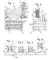
- the lath magazine 1 is adapted to be raised and lowered by means of a conventional guide means 4 (not described in further detail in this specification), driven by a pressure cylinder 5 whose piston 6 is connected to a wire 7 passing over a pulley 8 and fastened to the part of the guide that is connected to the lath magazine 1.
- the lath magazine 1 comprises two side walls la,lb whose distance apart is greater than the width of the laths, so that any crooked lath may easily pass down between the side walls la,lb without becoming wedged between the walls.
- two pressure cylinders 9 are provided, spaced apart from each other and positioned a distance above the bottom edge lc of the magazine corresponding to one lath thickness.
- the pressure cylinders 9 are attached to the side wall la in such manner that their pistons are urged forward into the magazine upon activation until they come in contact with a lath 3 within the magazine, pressing the lath 3 against the opposite wall lb of the magazine and thereby also supporting the overlying laths 3 in the magazine, as shown in Figure 2. If the magazine is empty, the cylinder pistons will extend somewhat farther into the magazine, and in that position they will serve as a bottom wall of the magazine for supporting a new supply of laths.
- Figure 5 shows the pressure cylinder again in the activated position, in which it presses the lath 3 immediately above the bottom lath against the side wall lb of the magazine, thereby also supporting the overlying stack 3' of laths
- Figure 6 shows the magazine land lath stack 3' in the elevated position with one lath 3 left behind in the correct position on the layer of boards 2a.
- a new layer 2a of planks or boards can then be formed on top of the spacer lath in a manner known per se, whereafter the magazine 1 is once again lowered for depositing a new spacer lath 3.
- the distance between the side walls la,lb of the magazine 1 is considerably larger than the width of the laths 3, so that despite any dimensional irregularities or nonuniformities of any kind, the laths can slide down freely between the walls of the magazine when the cylinder piston 9 is withdrawn.
- the free end of the piston rod preferably has a tapered or pointed configuration so that it preferably comes into contact with the center portion of one side edge of the lath. This ensures that even if the thickness of the laths varies considerably, the piston rod will abut against the side edge of the lath 3 and retain it (together with the overlying stack 3') within the magazine 1.
- two pressure cylinders are provided at the lower part of the magazine 1.
- one pressure cylinder 9 can be arranged at the middle section of said lower part of the magazine.
- the piston rod of the cylinder must in that case be provided with a clamping bar (not shown) extending parallel with the side edge of the lath 3, and the clamping bar upon activation of the cylinder will come into contact against a longer expanse of the side edge of the lath, thereby pressing the lath 3 against the opposite side wall lb of the magazine 1 and retaining it there.
- the pressure cylinders 9 For filling a new supply of spacer laths 3 into an empty magazine 1, elevated into the.upraised position, the pressure cylinders 9 must be activated such that the piston rods project transversely into the magazine 1 to form a support for the first lath 3 that is filled into the magazine, which supports overlying laths 3 in the stack 3'.
- the piston After the magazine has been lowered into contact against the upper layer 2a of the board stack 2, the piston is withdrawn, allowing the bottom lath 3 to fall down onto the boards 2a as discussed above, after which the piston is re-activated to bring it in contact with the next lath 3 in the stack, immediately above the lath that has been deposited on the boards, before the magazine 1 is again elevated as discussed above.
- the retaining means 9, which in the above-described embodiment constitute pressure cylinders, may take various other forms, and the invention is not restricted to the exemplary embodiment illustrated in this specification.
Landscapes
- Engineering & Computer Science (AREA)
- Mechanical Engineering (AREA)
- Stacking Of Articles And Auxiliary Devices (AREA)
- Packaging Of Special Articles (AREA)
- Ceramic Products (AREA)
- Photoreceptors In Electrophotography (AREA)
- Pile Receivers (AREA)
- Packages (AREA)
- Catching Or Destruction (AREA)
- Filling Or Discharging Of Gas Storage Vessels (AREA)
- Packaging Of Annular Or Rod-Shaped Articles, Wearing Apparel, Cassettes, Or The Like (AREA)
- Road Paving Structures (AREA)
- Cultivation Receptacles Or Flower-Pots, Or Pots For Seedlings (AREA)
Priority Applications (1)
| Application Number | Priority Date | Filing Date | Title |
|---|---|---|---|
| AT84850311T ATE24700T1 (de) | 1983-10-20 | 1984-10-19 | Verfahren zum absetzen von latten als abstandhalter zwischen bretterlagen in verbindung mit holzstapelmaschinen und lattenzufuehrmagazin zur durchfuehrung des verfahrens. |
Applications Claiming Priority (2)
| Application Number | Priority Date | Filing Date | Title |
|---|---|---|---|
| NO833830A NO153167C (no) | 1983-10-20 | 1983-10-20 | Fremgangsmaate for legging av stroe i et pakketeringsanlegg for trelast, og anordning ved stoemagasin for gjennomfoering av fremgangsmaaten. |
| NO833830 | 1983-10-20 |
Publications (2)
| Publication Number | Publication Date |
|---|---|
| EP0143092A1 true EP0143092A1 (de) | 1985-05-29 |
| EP0143092B1 EP0143092B1 (de) | 1987-01-07 |
Family
ID=19887300
Family Applications (1)
| Application Number | Title | Priority Date | Filing Date |
|---|---|---|---|
| EP84850311A Expired EP0143092B1 (de) | 1983-10-20 | 1984-10-19 | Verfahren zum Absetzen von Latten als Abstandhalter zwischen Bretterlagen in Verbindung mit Holzstapelmaschinen und Lattenzuführmagazin zur Durchführung des Verfahrens |
Country Status (5)
| Country | Link |
|---|---|
| EP (1) | EP0143092B1 (de) |
| AT (1) | ATE24700T1 (de) |
| DE (1) | DE3461912D1 (de) |
| FI (1) | FI76305C (de) |
| NO (1) | NO153167C (de) |
Cited By (8)
| Publication number | Priority date | Publication date | Assignee | Title |
|---|---|---|---|---|
| US4801233A (en) * | 1987-08-10 | 1989-01-31 | Harvey Industries, Inc. | Sticker placer apparatus |
| FR2628723A1 (fr) * | 1988-03-16 | 1989-09-22 | Man Francois | Dispositif de distribution de liteaux de separation de lits de pieces dans une machine a empilement |
| NO20093498A1 (no) * | 2009-12-09 | 2011-06-06 | Oesterboe Maskin As | En strølegger for utlegging av strø på et rørraster, samt en fremgangsmåte for utlegging av strø i et bukkesett. |
| CN108639768A (zh) * | 2018-06-28 | 2018-10-12 | 苏州博涵家居用品有限公司 | 一种填充设备自动上料机 |
| KR102070518B1 (ko) * | 2018-10-24 | 2020-01-28 | 김인수 | 목재 받침간목 자동공급 적재장치 |
| CN111776749A (zh) * | 2020-08-14 | 2020-10-16 | 蓬莱正泰木业有限公司 | 一种板材垛自动码垫条装置 |
| CN113695669A (zh) * | 2021-09-25 | 2021-11-26 | 厦门富全钢铁有限公司 | 一种钢板切割机的收料装置 |
| CN121698109A (zh) * | 2026-02-12 | 2026-03-20 | 东莞四维材料科技股份有限公司 | 一种隔离条放置装置和板材堆叠装置 |
Families Citing this family (1)
| Publication number | Priority date | Publication date | Assignee | Title |
|---|---|---|---|---|
| CN109610925B (zh) * | 2019-01-22 | 2024-10-18 | 江西天境精藏科技有限公司 | 交联连接式存放装置 |
Citations (4)
| Publication number | Priority date | Publication date | Assignee | Title |
|---|---|---|---|---|
| DE1259784B (de) * | 1965-05-25 | 1968-01-25 | Lawrence Engineering Company L | Vorrichtung zum Festklemmen der untersten Lage eines Palettenstapels |
| US3643621A (en) * | 1969-08-27 | 1972-02-22 | Ray William Newnes | Lumber stacker stick placer |
| FR2183746A1 (de) * | 1972-05-05 | 1973-12-21 | Elektromaschinenbau Veb K | |
| US4271980A (en) * | 1977-11-17 | 1981-06-09 | Elbak Batteriewerke Gesellschaft Mbh | Magazine for platelike articles |
Family Cites Families (2)
| Publication number | Priority date | Publication date | Assignee | Title |
|---|---|---|---|---|
| SE102427C1 (de) * | ||||
| IT958864B (it) * | 1972-05-13 | 1973-10-30 | Olivetti & Co Spa | Dispositivo per la sostituzione automatica di una cassetta contenen te un nastro magnetico in una appa recchiatura per la registrazione e o lettura del nastro contenuto in detta cassetta |
-
1983
- 1983-10-20 NO NO833830A patent/NO153167C/no unknown
-
1984
- 1984-10-19 FI FI844130A patent/FI76305C/fi not_active IP Right Cessation
- 1984-10-19 EP EP84850311A patent/EP0143092B1/de not_active Expired
- 1984-10-19 DE DE8484850311T patent/DE3461912D1/de not_active Expired
- 1984-10-19 AT AT84850311T patent/ATE24700T1/de not_active IP Right Cessation
Patent Citations (4)
| Publication number | Priority date | Publication date | Assignee | Title |
|---|---|---|---|---|
| DE1259784B (de) * | 1965-05-25 | 1968-01-25 | Lawrence Engineering Company L | Vorrichtung zum Festklemmen der untersten Lage eines Palettenstapels |
| US3643621A (en) * | 1969-08-27 | 1972-02-22 | Ray William Newnes | Lumber stacker stick placer |
| FR2183746A1 (de) * | 1972-05-05 | 1973-12-21 | Elektromaschinenbau Veb K | |
| US4271980A (en) * | 1977-11-17 | 1981-06-09 | Elbak Batteriewerke Gesellschaft Mbh | Magazine for platelike articles |
Cited By (11)
| Publication number | Priority date | Publication date | Assignee | Title |
|---|---|---|---|---|
| US4801233A (en) * | 1987-08-10 | 1989-01-31 | Harvey Industries, Inc. | Sticker placer apparatus |
| FR2628723A1 (fr) * | 1988-03-16 | 1989-09-22 | Man Francois | Dispositif de distribution de liteaux de separation de lits de pieces dans une machine a empilement |
| NO20093498A1 (no) * | 2009-12-09 | 2011-06-06 | Oesterboe Maskin As | En strølegger for utlegging av strø på et rørraster, samt en fremgangsmåte for utlegging av strø i et bukkesett. |
| CN108639768A (zh) * | 2018-06-28 | 2018-10-12 | 苏州博涵家居用品有限公司 | 一种填充设备自动上料机 |
| CN108639768B (zh) * | 2018-06-28 | 2024-02-13 | 苏州博涵家居用品有限公司 | 一种填充设备自动上料机 |
| KR102070518B1 (ko) * | 2018-10-24 | 2020-01-28 | 김인수 | 목재 받침간목 자동공급 적재장치 |
| CN111776749A (zh) * | 2020-08-14 | 2020-10-16 | 蓬莱正泰木业有限公司 | 一种板材垛自动码垫条装置 |
| CN113695669A (zh) * | 2021-09-25 | 2021-11-26 | 厦门富全钢铁有限公司 | 一种钢板切割机的收料装置 |
| CN113695669B (zh) * | 2021-09-25 | 2022-07-05 | 厦门富全钢铁有限公司 | 一种钢板切割机的收料装置 |
| CN121698109A (zh) * | 2026-02-12 | 2026-03-20 | 东莞四维材料科技股份有限公司 | 一种隔离条放置装置和板材堆叠装置 |
| CN121698109B (zh) * | 2026-02-12 | 2026-04-14 | 东莞四维材料科技股份有限公司 | 一种隔离条放置装置和板材堆叠装置 |
Also Published As
| Publication number | Publication date |
|---|---|
| ATE24700T1 (de) | 1987-01-15 |
| FI76305C (fi) | 1988-10-10 |
| FI76305B (fi) | 1988-06-30 |
| NO153167C (no) | 1986-01-29 |
| NO833830L (no) | 1985-04-22 |
| FI844130A0 (fi) | 1984-10-19 |
| NO153167B (no) | 1985-10-21 |
| FI844130L (fi) | 1985-04-21 |
| EP0143092B1 (de) | 1987-01-07 |
| DE3461912D1 (en) | 1987-02-12 |
Similar Documents
| Publication | Publication Date | Title |
|---|---|---|
| EP0143092B1 (de) | Verfahren zum Absetzen von Latten als Abstandhalter zwischen Bretterlagen in Verbindung mit Holzstapelmaschinen und Lattenzuführmagazin zur Durchführung des Verfahrens | |
| CN1118593A (zh) | 产生单个纸张堆垛的装置 | |
| SE463148B (sv) | Anordning foer matning av flata ark fraan en arkstapel med hjaelp av ett gaffelorgan | |
| US4750255A (en) | Machine for disassembling wood pallets | |
| JP2631043B2 (ja) | 積層シート状材料の切断装置及びその装置における搬送方法 | |
| US2981420A (en) | Piling machine for sheet-like materials | |
| EP0098854A1 (de) | Vorrichtung zum stapeln von holzbrettern mit zwischenbelattung. | |
| US4815924A (en) | Sheet stacking means after a cross-cutting saw | |
| EP0683036A1 (de) | Tafel aus Mineralwolle und Verfahren zu ihrer Herstellung | |
| US3968886A (en) | Sticker emplacer for a lumber stacker | |
| US4768640A (en) | Feed method and device for assembly parts | |
| CA2211384C (en) | Method and apparatus for high speed variable tier width lumber stacking | |
| CA2221072C (en) | Apparatus and method for drilling holes in dimensional lumber | |
| US3099301A (en) | Method of peg bundling and straightening lumber | |
| US7651327B2 (en) | Production line for producing sheets based on hydraulic binder and method of manufacturing the same | |
| US4079846A (en) | Apparatus and method for taking out a single sheet from a stack of veneer sheets | |
| US3602275A (en) | Woodworking machine | |
| US3372609A (en) | Method for drilling holes in articles, especially in books, and apparatus for utilizing the method | |
| US5244341A (en) | Lath placer | |
| US3872903A (en) | Multiple shake-board splitting method | |
| US3467253A (en) | Method and an apparatus for the sorting by length of sawn and planed timber and for the piling of the same | |
| JPH0253549B2 (de) | ||
| GB2370828A (en) | Gripper and method of unstacking elongate work pieces | |
| US3521770A (en) | Method for forming a bundle of sawn or planed boards or planks,sorted as to length | |
| DE19912171C2 (de) | Holzlattenstapelvorrichtung |
Legal Events
| Date | Code | Title | Description |
|---|---|---|---|
| PUAI | Public reference made under article 153(3) epc to a published international application that has entered the european phase |
Free format text: ORIGINAL CODE: 0009012 |
|
| AK | Designated contracting states |
Designated state(s): AT DE FR SE |
|
| 17P | Request for examination filed |
Effective date: 19851028 |
|
| 17Q | First examination report despatched |
Effective date: 19860228 |
|
| GRAA | (expected) grant |
Free format text: ORIGINAL CODE: 0009210 |
|
| AK | Designated contracting states |
Kind code of ref document: B1 Designated state(s): AT DE FR SE |
|
| REF | Corresponds to: |
Ref document number: 24700 Country of ref document: AT Date of ref document: 19870115 Kind code of ref document: T |
|
| REF | Corresponds to: |
Ref document number: 3461912 Country of ref document: DE Date of ref document: 19870212 |
|
| ET | Fr: translation filed | ||
| PLBE | No opposition filed within time limit |
Free format text: ORIGINAL CODE: 0009261 |
|
| STAA | Information on the status of an ep patent application or granted ep patent |
Free format text: STATUS: NO OPPOSITION FILED WITHIN TIME LIMIT |
|
| 26N | No opposition filed | ||
| PGFP | Annual fee paid to national office [announced via postgrant information from national office to epo] |
Ref country code: SE Payment date: 19901022 Year of fee payment: 7 |
|
| PGFP | Annual fee paid to national office [announced via postgrant information from national office to epo] |
Ref country code: AT Payment date: 19901023 Year of fee payment: 7 |
|
| PGFP | Annual fee paid to national office [announced via postgrant information from national office to epo] |
Ref country code: FR Payment date: 19901029 Year of fee payment: 7 |
|
| PGFP | Annual fee paid to national office [announced via postgrant information from national office to epo] |
Ref country code: DE Payment date: 19901130 Year of fee payment: 7 |
|
| PG25 | Lapsed in a contracting state [announced via postgrant information from national office to epo] |
Ref country code: AT Effective date: 19911019 |
|
| PG25 | Lapsed in a contracting state [announced via postgrant information from national office to epo] |
Ref country code: SE Effective date: 19911020 |
|
| PG25 | Lapsed in a contracting state [announced via postgrant information from national office to epo] |
Ref country code: FR Effective date: 19920630 |
|
| PG25 | Lapsed in a contracting state [announced via postgrant information from national office to epo] |
Ref country code: DE Effective date: 19920701 |
|
| REG | Reference to a national code |
Ref country code: FR Ref legal event code: ST |
|
| EUG | Se: european patent has lapsed |
Ref document number: 84850311.6 Effective date: 19920510 |