EP0142779A2 - Anordnung zur automatischen variablen Regelung von Bildschirmparametern - Google Patents
Anordnung zur automatischen variablen Regelung von Bildschirmparametern Download PDFInfo
- Publication number
- EP0142779A2 EP0142779A2 EP84113461A EP84113461A EP0142779A2 EP 0142779 A2 EP0142779 A2 EP 0142779A2 EP 84113461 A EP84113461 A EP 84113461A EP 84113461 A EP84113461 A EP 84113461A EP 0142779 A2 EP0142779 A2 EP 0142779A2
- Authority
- EP
- European Patent Office
- Prior art keywords
- pulse train
- frequency
- pulse
- level
- track ball
- Prior art date
- Legal status (The legal status is an assumption and is not a legal conclusion. Google has not performed a legal analysis and makes no representation as to the accuracy of the status listed.)
- Ceased
Links
Images



Classifications
-
- G—PHYSICS
- G06—COMPUTING OR CALCULATING; COUNTING
- G06F—ELECTRIC DIGITAL DATA PROCESSING
- G06F7/00—Methods or arrangements for processing data by operating upon the order or content of the data handled
- G06F7/60—Methods or arrangements for performing computations using a digital non-denominational number representation, i.e. number representation without radix; Computing devices using combinations of denominational and non-denominational quantity representations, e.g. using difunction pulse trains, STEELE computers, phase computers
- G06F7/68—Methods or arrangements for performing computations using a digital non-denominational number representation, i.e. number representation without radix; Computing devices using combinations of denominational and non-denominational quantity representations, e.g. using difunction pulse trains, STEELE computers, phase computers using pulse rate multipliers or dividers pulse rate multipliers or dividers per se
-
- G—PHYSICS
- G09—EDUCATION; CRYPTOGRAPHY; DISPLAY; ADVERTISING; SEALS
- G09G—ARRANGEMENTS OR CIRCUITS FOR CONTROL OF INDICATING DEVICES USING STATIC MEANS TO PRESENT VARIABLE INFORMATION
- G09G5/00—Control arrangements or circuits for visual indicators common to cathode-ray tube indicators and other visual indicators
- G09G5/10—Intensity circuits
Definitions
- This invention relates generally to the control of video display parameters and the like, and more particularly the invention relates to a method and means for automatically variably controlling display parameters to achieve rapid and smooth transitions with precision from one parameter value to another parameter value.
- CT values which can vary from 0 to 4095 in the General Electric 9800-CT system.
- CT numbers are .proportional to the x-ray attenuation by small volume elements in the body being scanned with the x-ray beam.
- the CT values are displayed on a cathode ray tube as levels of gray.
- the conventional video display is capable of displaying only about 256 gray levels between a black level and a white level. Accordingly, it has been the practice to select from a large range of CT values a limited range called a window and to display picture elements having CT values within the window over the gray scale capability of the CRT.
- CT values above the upper window limit are white and those below the lower window limit are black. See, for example, U. S. Patent No. 4,105,922 for "CT Member Identifier In A Computed Tomography System.”
- An operator control called LEVEL is provided in a CT display system to establish the center of a selected window of CT values to be displayed on the image monitor. This will then cause pixel values equal to the level setting to be displayed as middle Gray while CT values greater than the upper limit of the window are displayed as white pixels and CT values less than the lower limit are displayed as black pixels. Intermediate CT values are then displayed as various shades of gray depending upon their relative position within the selected window.
- the manually operated level control must have sufficient range of speed for a desired value to be quickly reached with a minimum of effort.
- two speed rocker switches or a rotary knob have been provided for handling the level control adjustment.
- excessive manual operation is needed to vary the display window over the full range of CT numbers.
- an object of the present invention is a method of varying the rate of change of a parameter to achieve rapid and exact changes.
- Another object of the invention is apparatus for varying the rate of change of a parameter in response to a manually operated control.
- a feature of the invention in accordance with one embodiment is apparatus responsive to the duration of change of a parameter for automatically varying the rate of change of the parameter.
- Another feature of the invention in accordance with another embodiment is logic coding means for non-linearly varying the rate of change of a parameter based on rate of change of a manually operated control.
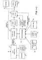
- FIG. 1 is a functional block diagram of a portion of a CRT display apparatus for use with a CT system.
- the CT system (not shown), includina patient table, radiation source, and detectors is controlled by a host computer 10 which typically has a keyboard 12 and an alphanumeric monitor 14 associated therewith.
- Data from the host computer 10 is interconnected to interface hardware 16 of the display controller through an interface cable 18.
- the interface hardware operates under control of a microprocessor 20 which has associated therewith miscellaneous control keys 22, cursor select key 24, and a manually operated control such as a track ball 26 for movement of the cursor.
- Data from the interface hardware 16 is stored in an image memory 28 from which it is passed through a video output 30 to the CRT image monitor 32.
- a camera 34 can be provided with the output for recording the displayed image.
- the window level control hardware 36 Associated with the video output 30 under control of microprocessor 20 is the window level control hardware 36.
- the window level control hardware has heretofore included manually operated rocker switches or a rotary knob for providing the window level control adjustment.
- such manually operated controls are not feasible for in with a CT system having a large range of CT values for the level control.
- Figure 2 is a plot of CT values versus screen grey levels which illustrates the displayed window portion of the CT data.
- the window has a limited width for the displayed CT data, and the center of the window or the intermediate level of the displayed CT data, designated the window level, is movable to vary the CT numbers displayed.
- control apparatus in either hardware or firmware is provided for varying the speed of level change in response to a manually operated control.
- the track ball used for a cursor control can be used for level control, also.
- the rate of level change will be automatically increased for rapidly effecting a level change and will be automatically decreased to establish an exact level for CT number display.
- the track ball is the equivalent of an electronic joy stick and comprises a smooth ball which is supported for revolving in all directions in a socket in a control console.
- a hemisphere of the ball is exposed so that an operator may rotate the ball by finger touch and Watch the line or outline develop on the display screen.
- the concealed hemisphere of the ball rests on at least a pair of rollers which drive encoders. The encoders produce trains of electric pulses when the ball is turned.
- FIG. 3 is a functional block diagram of logic hardware for variably controlling the level of the CRT display in accordance with one embodiment of the invention.
- rotation of track ball 40 generates a train of pulses the frequency of which depends on rotation speed of the track ball.
- the pulse train is applied to a frequency to voltage converter 42 which provides a DC output voltage proportional to the frequency of the pulse train input.
- the output voltage from the converter 42 is then applied to a plurality of voltage comparators 44, 46, and 48.
- One input of each of the voltage comparators is connected to a resistive voltage divider shown generally at 50 which is connected between a reference voltage, Vref, and circuit ground.
- Each of the voltage comparators provides an output voltage depending on the comparison of the reference voltage from the voltage divider 50 and the voltage from converter 42.
- the output voltage from the voltage converter 42 and the outputs from the voltage comparators 44-48 are illustrated in Figure 4A.
- the output signal from each of the comparators has a transition when the voltage from converter 42 exceeds the reference voltage applied to the comparator.
- the output of comparator 44 has the initial transition since its reference voltage is lowest, whereas the output from comparator 48 occurs later since it has the largest reference voltage applied thereto.
- the outputs from voltage comparators 44-48 are applied to coding circuitry 52 which generates four outputs E1-E4, as illustrated in Figure 4B.
- Each of the outputs E1-E4 is applied to one input of the AND gates 54, 56, 58, and 60.
- the other input to AND gate 54 is the pulse train from the output of track ball 40
- the other input to AND gate 56 is derived by dividing the output of an oscillator 62 by dividers 64 and 66
- the other input to AND gate 58 is derived by dividing the output of oscillator 62 by divider 64
- the other input to AND gate 60 is derived directly from the output of oscillator 62.
- AND gate 54 will produce an output only when the track ball 40 is moving an a minimal speed, whereupon the slow pulse train from track ball 40 is applied at the output of AND gate 54.
- AND gate 60 will provide an output derived directly from the high frequency oscillator 62.
- AND gates 56 and 56 provide intermediate frequencies derived from the dividers 64 and 66, as described, for intermediate frequencies of the pulse train at the output of track ball 40.
- the outputs from the AND gates 54-60 are applied to OR gate 68 which in turn provides a pulse train to the window level circuitry for level adjustment.
- the apparatus non-linearly responds to the movement of track ball 40 to accelerate changes in window level or to more slowly establish an exact level.
- the operator can accelerate change of the display level by rapid movement of the track ball 40, and a slower movement for exact level setting is obtained by moving the track ball 40 slowly.
- Figure 5 is a plot of the track ball speed versus level change speed.
- the curve 70 illustrates the four different pulse rates or speeds which can be obtained using the circuitry of Figure 3.
- Curve 72 is a smoother curve which can be realized by using additional voltage comparators and pulse rates.
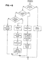
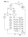
- FIGS. 6 and 7 are flow diagrams of portions of a computer program for implementing the invention. In the flow diagrams the following nomenclature is employed:
- the track ball has four modes, the first mode being for controlling the cursor of the display and the other three modes being for controlling the level change rate.
- Mode 3 M3, is an accelerated rate change with the rate being determined by a variable, R, which represents the number of pulses generated by the track ball in one frame period of the CRT (1/60 second).
- R represents the number of pulses generated by the track ball in one frame period of the CRT (1/60 second).
- modes Ml and M2 the pulse output from the track ball is divided by four and applied to control the level.
- the symbol delta, ⁇ has a value of +1 for upward track movement (e.g. increased level), and a value of -1 for downward track motion (e.g. decreased level).
- V is the value count used in the modes 1 and 2 to divide the track ball generated pulses and thereby reduce the change of level speed.
- F is the frame count used to reset the track ball mode to a slow speed after five consecutive frames with no track ball motion.
- Figure 6 is a flow diagram for the track ball interrupt program.
- the mode M for the track ball is determined, and if the mode equals zero then the track ball merely moves the cursor. If the mode does not equal zero, then the accelerated mode is identified if M equal 3. If in the accelerated mode then frame count is set to 5, the level is non-linearly changed by an amount dependent upon the repeat count (R), and the repeat count is incremented, as will be described with respect to Figure 7.
- the level is incremented if the fourth track ball pulse is identified (e.g. pulse output is divided by four).
- the accelerated mode is entered if the stored count R from the preceding frame exceeds a predetermined threshold level and thereupon the frame count is set to 5. The track ball move count is reset.
- the mode is M1 or M2 and the track ball count is not four, then the number of track ball moves is counted and stored.
- V the value count, V, is decremented if not zero. If V is zero, then the level, L, is incremented, the mode, M, is incremented, frame count is set to 5, R is set to zero indicating the trackball movement, and the value, V, is set to 3 for subsequent decrementing to achieve a one-fourth reduction in count of trackball pulses.
- Figure 8 is the flow diagram for the program used in exiting the accelerated mode. Again, the track ball mode is determined and if zero then the cursor is being controlled. If the frame count is not zero then the frame count is decremented and if then equal to zero the accelerated mode is exited because no change has occured in the previous five frames. Thus, the accelerated mode (M3) is entered when track ball movement in one frame exceeds a set level, and acceleration mode is exited when no movement occurs in five consecutive frames.
Landscapes
- Engineering & Computer Science (AREA)
- General Physics & Mathematics (AREA)
- Theoretical Computer Science (AREA)
- Physics & Mathematics (AREA)
- Pure & Applied Mathematics (AREA)
- Mathematical Analysis (AREA)
- Mathematical Optimization (AREA)
- Mathematical Physics (AREA)
- Computing Systems (AREA)
- General Engineering & Computer Science (AREA)
- Computational Mathematics (AREA)
- Computer Hardware Design (AREA)
- Apparatus For Radiation Diagnosis (AREA)
- Magnetic Resonance Imaging Apparatus (AREA)
- Digital Computer Display Output (AREA)
- Closed-Circuit Television Systems (AREA)
Applications Claiming Priority (2)
| Application Number | Priority Date | Filing Date | Title |
|---|---|---|---|
| US06/552,664 US4563740A (en) | 1983-11-17 | 1983-11-17 | Method and means for automatically variably controlling display parameters |
| US552664 | 1983-11-17 |
Publications (2)
| Publication Number | Publication Date |
|---|---|
| EP0142779A2 true EP0142779A2 (de) | 1985-05-29 |
| EP0142779A3 EP0142779A3 (de) | 1989-01-11 |
Family
ID=24206274
Family Applications (1)
| Application Number | Title | Priority Date | Filing Date |
|---|---|---|---|
| EP84113461A Ceased EP0142779A3 (de) | 1983-11-17 | 1984-11-08 | Anordnung zur automatischen variablen Regelung von Bildschirmparametern |
Country Status (4)
| Country | Link |
|---|---|
| US (1) | US4563740A (de) |
| EP (1) | EP0142779A3 (de) |
| JP (1) | JPS60153541A (de) |
| IL (1) | IL72919A (de) |
Cited By (1)
| Publication number | Priority date | Publication date | Assignee | Title |
|---|---|---|---|---|
| EP0330270A1 (de) * | 1988-02-23 | 1989-08-30 | Koninklijke Philips Electronics N.V. | Arbeitsstation mit stetig änderbarer Empfindlichkeitseinstellung der Positionssteueranordnung |
Families Citing this family (17)
| Publication number | Priority date | Publication date | Assignee | Title |
|---|---|---|---|---|
| JPS6029833A (ja) * | 1983-07-28 | 1985-02-15 | Canon Inc | 画像表示装置 |
| US4839805A (en) * | 1983-11-17 | 1989-06-13 | General Electric Company | Dual control of image level and window parameters of a display and the like |
| IL71878A (en) * | 1984-05-21 | 1987-11-30 | Elscint Ltd | Intensity level windowing system for image displays |
| US5195179A (en) * | 1986-01-29 | 1993-03-16 | Hitachi, Ltd. | Coordinate input apparatus |
| JPH0759082B2 (ja) * | 1986-02-14 | 1995-06-21 | 株式会社東芝 | マルチイメ−ジ自動撮影装置 |
| JPH082744Y2 (ja) * | 1986-05-06 | 1996-01-29 | カシオ計算機株式会社 | 座標入力デ−タ処理装置 |
| US4839838A (en) * | 1987-03-30 | 1989-06-13 | Labiche Mitchell | Spatial input apparatus |
| DE3716892A1 (de) * | 1987-05-20 | 1988-12-01 | Fresenius Ag | Vorrichtung zur eingabe von numerischen bzw. alphanumerischen daten in ein geraet |
| JPH0217528A (ja) * | 1988-07-06 | 1990-01-22 | Toshiba Corp | ウインドウ処理装置 |
| US5239292A (en) * | 1988-10-04 | 1993-08-24 | Crosfield Electronics Ltd. | Computer graphics system electronically simulating painting on canvas |
| US5012231A (en) * | 1988-12-20 | 1991-04-30 | Golemics, Inc. | Method and apparatus for cursor motion having variable response |
| JP2714164B2 (ja) * | 1989-07-31 | 1998-02-16 | 株式会社東芝 | 三次元画像表示装置 |
| US5293313A (en) * | 1990-11-21 | 1994-03-08 | Picker International, Inc. | Real time physician view box |
| JPH04191797A (ja) * | 1990-11-27 | 1992-07-10 | Toshiba Corp | ディスプレイシステム |
| JPH04218824A (ja) * | 1990-12-19 | 1992-08-10 | Yaskawa Electric Corp | 多次元情報入力装置 |
| US5764219A (en) * | 1992-09-25 | 1998-06-09 | Ibm Corporation | Controller for improved computer pointing devices |
| JP3627427B2 (ja) * | 1997-02-03 | 2005-03-09 | 富士ゼロックス株式会社 | データ出力システム |
Family Cites Families (14)
| Publication number | Priority date | Publication date | Assignee | Title |
|---|---|---|---|---|
| US3355539A (en) * | 1963-09-27 | 1967-11-28 | Baldwin Co D H | Sampling tone generator system for electronic organs |
| US3541521A (en) * | 1967-12-11 | 1970-11-17 | Bunker Ramo | Multiple ratio cursor control system |
| US3729129A (en) * | 1971-06-22 | 1973-04-24 | Nasa | Numerical computer peripheral interactive device with manual controls |
| US4122518A (en) * | 1976-05-17 | 1978-10-24 | The United States Of America As Represented By The Administrator Of The National Aeronautics & Space Administration | Automated clinical system for chromosome analysis |
| US4105922A (en) * | 1977-04-11 | 1978-08-08 | General Electric Company | CT number identifier in a computed tomography system |
| US4223257A (en) * | 1978-11-15 | 1980-09-16 | Miller Donald K | Adaptive servo control system |
| US4259725A (en) * | 1979-03-01 | 1981-03-31 | General Electric Company | Cursor generator for use in computerized tomography and other image display systems |
| DE2932564C2 (de) * | 1979-08-10 | 1982-05-27 | Siemens Ag, 1000 Berlin Und 8000 Muenchen | Schaltungsanordnung zum Verschieben einer Marke über den Bildschirm eines Sichtgerätes |
| US4318045A (en) * | 1980-04-10 | 1982-03-02 | Rca Corporation | Symmetrical waveform signal generator having coherent frequency shift capability |
| JPS56163411A (en) * | 1980-05-20 | 1981-12-16 | Canon Inc | Progammable joy stick |
| US4454507A (en) * | 1982-01-04 | 1984-06-12 | General Electric Company | Real-time cursor generator |
| WO1983002835A1 (en) * | 1982-02-09 | 1983-08-18 | Solomon, Edward, G. | Multi-digit parameter setting procedure |
| US4521843A (en) * | 1982-08-16 | 1985-06-04 | Intermatic Incorporated | Programmable wall switch for controlling lighting times and loads |
| US4493992A (en) * | 1982-08-23 | 1985-01-15 | Wico Corporation | Adapter circuit for trackball device |
-
1983
- 1983-11-17 US US06/552,664 patent/US4563740A/en not_active Expired - Fee Related
-
1984
- 1984-09-12 IL IL72919A patent/IL72919A/xx unknown
- 1984-11-08 EP EP84113461A patent/EP0142779A3/de not_active Ceased
- 1984-11-16 JP JP59240915A patent/JPS60153541A/ja active Pending
Cited By (1)
| Publication number | Priority date | Publication date | Assignee | Title |
|---|---|---|---|---|
| EP0330270A1 (de) * | 1988-02-23 | 1989-08-30 | Koninklijke Philips Electronics N.V. | Arbeitsstation mit stetig änderbarer Empfindlichkeitseinstellung der Positionssteueranordnung |
Also Published As
| Publication number | Publication date |
|---|---|
| JPS60153541A (ja) | 1985-08-13 |
| IL72919A0 (en) | 1984-12-31 |
| EP0142779A3 (de) | 1989-01-11 |
| US4563740A (en) | 1986-01-07 |
| IL72919A (en) | 1987-12-20 |
Similar Documents
| Publication | Publication Date | Title |
|---|---|---|
| US4563740A (en) | Method and means for automatically variably controlling display parameters | |
| US3944731A (en) | Video special effects generator | |
| US4454507A (en) | Real-time cursor generator | |
| US5469209A (en) | Apparatus for generating video signals representing a photographic image previously recorded in a frame on a photographic film-type medium | |
| US4386346A (en) | Cursor controller | |
| US4591897A (en) | System for generating a display of graphic objects over a video camera picture | |
| US4239351A (en) | Apparatus for generating and displaying visual acuity targets | |
| US4360805A (en) | Digital erase of raster lines | |
| US8085075B2 (en) | Method and system for diagnostic imaging using a digital phase locked loop | |
| CA1158374A (en) | Display system for localizing regions in a mixed text and picture display | |
| EP0187262B1 (de) | Vorrichtung zur Bildmanipulation am Videobildschirm | |
| US4839805A (en) | Dual control of image level and window parameters of a display and the like | |
| US20050074085A1 (en) | Methods and apparatus for dynamical helical scanned image production | |
| US4400728A (en) | Video process control apparatus | |
| EP0564551A1 (de) | Dynamische impulssteuerung für röntgendurchleuchtung. | |
| US4086492A (en) | Display apparatus for use in radiography | |
| DE60032569T2 (de) | Verfahren und Geräte zur ungleichförmigen zeitlichen Herzbildgebung | |
| CA2021620A1 (en) | Method for reducing patient translation artifacts in tomographic imaging | |
| DE102006020812A1 (de) | Verfahren und Systeme zur Belichtungssteuerung für medizinische Bildgebungsgeräte | |
| GB1577641A (en) | X-ray system having a driving mechanism for an x-ray sourc and an x-ray detector | |
| US3816651A (en) | Automated image analysis employing automatic focussing | |
| US4952081A (en) | Manual rotary sphere control of an electronic equipment with touch sensing of scale marks | |
| EP0173111B1 (de) | Programmierbarer Videomaskengenerator | |
| DE19854472A1 (de) | Gerät und Verfahren zur Anzeige von Computer-Tomographie-Fluoroskopiebildern | |
| US4217642A (en) | Method and apparatus for locating data characterizing blood flow through the heart |
Legal Events
| Date | Code | Title | Description |
|---|---|---|---|
| PUAI | Public reference made under article 153(3) epc to a published international application that has entered the european phase |
Free format text: ORIGINAL CODE: 0009012 |
|
| AK | Designated contracting states |
Designated state(s): DE FR GB NL |
|
| PUAL | Search report despatched |
Free format text: ORIGINAL CODE: 0009013 |
|
| AK | Designated contracting states |
Kind code of ref document: A3 Designated state(s): DE FR GB NL |
|
| 17P | Request for examination filed |
Effective date: 19890630 |
|
| 17Q | First examination report despatched |
Effective date: 19900515 |
|
| STAA | Information on the status of an ep patent application or granted ep patent |
Free format text: STATUS: THE APPLICATION HAS BEEN REFUSED |
|
| 18R | Application refused |
Effective date: 19910531 |
|
| RIN1 | Information on inventor provided before grant (corrected) |
Inventor name: BLAKE, JAMES EDWARD Inventor name: HAJICEK, JAMES DONALD |