EP0142223B1 - Als integrierte Einheit ausgebildetes Ensemble zur intravenösen Infusion - Google Patents
Als integrierte Einheit ausgebildetes Ensemble zur intravenösen Infusion Download PDFInfo
- Publication number
- EP0142223B1 EP0142223B1 EP19840305592 EP84305592A EP0142223B1 EP 0142223 B1 EP0142223 B1 EP 0142223B1 EP 19840305592 EP19840305592 EP 19840305592 EP 84305592 A EP84305592 A EP 84305592A EP 0142223 B1 EP0142223 B1 EP 0142223B1
- Authority
- EP
- European Patent Office
- Prior art keywords
- tubing
- catheter
- gripping member
- hub
- polyurethane
- Prior art date
- Legal status (The legal status is an assumption and is not a legal conclusion. Google has not performed a legal analysis and makes no representation as to the accuracy of the status listed.)
- Expired
Links
Images
Classifications
-
- A—HUMAN NECESSITIES
- A61—MEDICAL OR VETERINARY SCIENCE; HYGIENE
- A61M—DEVICES FOR INTRODUCING MEDIA INTO, OR ONTO, THE BODY; DEVICES FOR TRANSDUCING BODY MEDIA OR FOR TAKING MEDIA FROM THE BODY; DEVICES FOR PRODUCING OR ENDING SLEEP OR STUPOR
- A61M25/00—Catheters; Hollow probes
- A61M25/0009—Making of catheters or other medical or surgical tubes
- A61M25/0014—Connecting a tube to a hub
Definitions
- This invention relates generally to intravenous infusion and, more particularly, to a winged catheter for intravenous infusion which is assembled from a plurality of polyurethane parts and formed into an integral unit by means of dielectric heating using radio frequency energy.
- Commonly used intravenous infusion assemblies comprise needle and catheter sets wherein a needle extends within a flexible catheter having so-called "wings" attached to the catheter assembly. For insertion, one grips the wings, squeezing them between the thumb and forefinger, to assist in accurately positioning the catheter sheathed needle into a desired vein.
- a typical infusion assembly comprises a catheter, a winged catheter gripping member, a section of tubing and a fluid receiving hub.
- a variety of methods have been utilized to interconnect the parts making up such an assembly.
- the parts have been mechanically interconnected byforcing a conical wedge into the proximal end of the catheter to lockthe catheter in the catheter hu b.
- Such mechanical interconnection is often referred to as "staking” or “swedging” and can be expensive and time consuming.
- the presence of the wedge in the infusion stream creates turbulent flow which can interfere with metering the infusion liquid.
- the parts have also been glued together by means of an appropriate adhesive.
- gluing requires a biocompatible adhesive and is typically messy. Gluing also can lead to inadvertent blockage of a portion of the assembly passageway particularly when small gauge catheters are utilized.
- Solvent bonding has also been utilized.
- each of the parts is made from a material which is soluble in a particular solvent.
- solvent bonding has proved to be only marginally reliable in preventing leakage.
- Solvent bonding also is expensive and time consuming when used for the assembly of intravenous infusion devices.
- Radio frequency welding or bonding has not been applied in the manufacture of intravenous infusion assemblies. Problems encountered in RF bonding have centered around the frequencies and power levels utilized as well as the formation of the power applying electrodes. For example, if insufficient power is applied to the parts, the welds or bonds are not reliable. On the other hand, excessive power can lead to arcing of the radio frequency energy at the electrodes and may damage the RF power supply and/or cause the small openings of the passageways through the intravenous infusion assembly to be blocked.
- a unitary winged catheter assembly suitable for intravenous infusion is formed as an integral unit from a plurality of polyurethane parts of varying degrees of hardness by means of wetding the parts together using dielectric heating created by radio frequency energy.
- a unitary winged catheter assembly suitable for use in intravenous infusion which is formed as an integral unit from a plurality of polyurethane parts of varying degrees of hardness, the polyurethane parts being dielectrically welded together into said unitary assembly, the assembly comprising:
- mating surfaces of the first, second and third joints are joined together by dielectric welding for commingling the materials of the mating surfaces, and the internal diameters of the first, second and third joints are sufficient to receive an electrode for the dielectric welding.
- steps (i), (iii) and (v) are effected contemporaneously, or steps (i), (iii) and (v) are effected in any order with respect to each other; and steps (ii), (iv) and (vi) may be effected contemporaneously.
- catheter assemblies bonded by radio frequency heating in accordance with the present invention are particularly advantageous because the assembly can be manufactured from parts made from polyurethanes having the same or different shore hardness ratings and yet these parts can be integrally bonded together such that there is intermingling of their constituent polymers and they cannot be separated.
- a section of flexible polyurethane tubing is inserted into a polyurethane fluid receiving hub and radio frequency energy is applied to the portion of the hub into .which the tubing is inserted to heat the tubing and the hub such that they melt into one another to form a reliable weld or bond.
- the fluid receiving hub includes tubing stop means, for example, an internal shoulder sized to engage the end of the tubing, for defining a tubing insertion point beyond which the tubing cannot be inserted into the hub.
- the opposite end of the tubing section may be inserted into a generally cylindrical central portion of a polyurethane winged catheter gripping member and radio frequency energy is again applied to weld the two together as if the two were a single part.
- the catheter gripping member includes a pair of wings flexibly connected to the central portion and having a relaxed condition wherein the wings extend in a generally transverse direction to the central portion, yet the wings are sufficiently flexible that they can be moved into facing engagement with one another for placement of the catheter into a selected vein.
- a generally cylindrical polyurethane catheter has its proximal end inserted into a canal in the generally cylindrical central portion of the catheter gripping member and is welded to it by the application of radio frequency energy with the catheter having its tapered distal end extending from the gripping member for insertion into a vein.
- Such assembly and welding operations using radio frequency energy provide a winged catheter assembly which is an integral unit, i.e., the individual elements forming the infusion assembly are so bonded to one another that the polymers at the interface of two adjacent parts are intermingled.
- the process for making said unitary polyurethane winged catheter assembly for intravenous infusion including a fluid receiving hub, a winged catheter gripping member, tubing for interconnecting the hub to the gripping member, and a catheter, all of which are formed from polyurethane compounds, comprises the steps of interconnecting the individual parts together and applying the appropriate frequency and energy levels of RF energy to the section of the parts receiving the tubing and the catheter such that the polyurethane compounds of the energised portions of the parts are heated to flow into one another to form an integral winged catheter assembly.
- an object of the present invention to provide an improved intravenous infusion assembly which is formed as an integral unit from a plurality of parts made from polyurethane compounds of different hardness with the individual parts being assembled and welded to form an integral unit by means of the application of the appropriate frequency and energy levels of radio frequency energy to interengaging portions of the assembly to thereby fuse the interengaging portions of the respective parts and firmly weld them to one another.
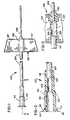
- an intravenous infusion assembly 100 in accordance with the present invention comprises a fluid receiving hub 102, a section of flexible tubing 104, a winged catheter gripping member 106 and a catheter 108 all formed into an integral unit by means of radio frequency welding or bonding as will be described hereinafter.
- the fluid receiving hub 102 shown in cross-section in Fig. 2, comprises a hollow, generally cylindrical, body molded from a relatively rigid polyurethane compound.
- the polyurethane forming the hub has a Shore Durometer D hardness of about 50 to 75 and the polyurethane forming the tubing has a Shore Durometer A of about 75 to 95.
- the proximal end of the hub 102 has a collar 110 with radially and circumferentially extending lugs 112 that may be used with conventional equipment employing Luer locks for external connection to a source of infusion fluid.
- Reinforcing ribs 114 run approximately two-thirds of the way along the hub from the collar 110 toward the distal end of the hub.
- the hub 102 comprises a primary fluid receiving cavity 116 opening to its proximal end and a tubing receiving canal 118 opening to the distal end of the hub 102.
- the primary fluid receiving cavity 116 and the tubing receiving canal 118 are interconnected by a diameter reducing frustocon- ical section 120 and a generally cylindrical interconnecting canal 122 which is of a smaller diameter than the diameter of the generally cylindrical tubing receiving canal 118.
- the reduced diameter canal 122 forms a tubing stop means or shoulder 124 such that when the tubing 104 is inserted into the tubing receiving canal 118, it is extended only until it engages the shoulder 124 to provide a selected or defined length of the tubing 104 extending into the hub 102.
- the winged catheter gripping member 106 comprises a generally cylindrical central portion 126 to which the wings 127 are flexibly connected.
- the gripping member is preferably formed from a relatively soft polyurethane e.g., one having a Shore Durometer A hardness of about 75 to 90 such that the wings 127, as shown in Fig. 1, can be folded upwardly into facing engagement with one another and be firmly gripped between the thumb and forefinger of a person inserting the catheter assembly into a vein of a patient.
- a cannula or needle (not shown) is included within the catheter assembly 100 for insertion of the catheter 108 into a vein as is well known in the art.
- the generally cylindrical central portion 126 of the member 106 shown in cross-section in Fig. 3, includes a first opening 128 toward its proximal end sized to frictionally receive the distal end of the tubing 104.
- the exact insertion depth of the tubing 104 into the opening 128 is not critical. It is only necessary that the tubing 104 extend a sufficient distance into the passageway 128 such that it may be securely welded by means of dielectric heating generated by RF energy applied to the central portion 126 as will be described hereinafter.
- the distal end of the central portion 126 includes a downsized opening 130 which is sized to receive the proximal end of the catheter 108.
- the catheter 108 may be inserted a varying depth into the opening 130 and, again, the only requirement is that a sufficient insertion depth be made such that the catheter 108 and the surrounding portion of the central section 128 forming the opening 130 may be firmly welded to one another by means of dielectric heating.
- a particular advantage of the present invention is that an integral catheter assembly can be formed from polyurethane elements without unduly restricting the nature of the polyurethane which forms the catheter.
- the catheter can be formed from a polyurethane which is hard enough to be inserted through the skin on a cannula but is sufficiently pliable as to not scratch or damage the inside wall of a vein or artery into which the catheter is inserted.
- Polyurethanes used for this purpose usually have a Shore Durometer D hardness of about 55 to 70.
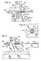
- Fig. 4 shows a jig for welding the tubing 104 to the hub 102 and Fig. 5 shows a jig for welding the tubing 104 into the central portion 126 of the winged catheter gripping member 106.
- RF energy from a Solidyne KH 8 RF generator from Solidyne, Inc. (not shown) is connected to terminal lugs 132 and 134 of the jigs shown in Fig. 4 and 5, respectively which in turn are connected to a metal pin 136 on which the catheter assembly is mounted as it is welded.
- An alternating current is delivered to the pin 136 by the generator which causes the polarity of the pin to rapidly oscillate between a highly positive and a highly negative polarity with respect to ground.
- an alternating electric field is set up between the pin 136 and the electrodes 140 which are grounded.
- electrodes 140 are designed with smaller dimension tips 141 where the field is concentrated.
- the portions of the catheter assembly in the alternating field between the electrode tips 141 heat in a known manner. It is not essential that there be a space between the catheter assembly 100 and the ground electrodes 140 to prevent arcing. Sharp points and edges should be avoided in the electrodes wherever possible since these are the first places breakdown occurs.
- a generally cylindrical pin 136 extends from the framework 138 of the jig shown in Fig. 4 with the generally cylindrical pin 136 being connected to the RF generator.
- the ground electrodes 140 an end view of which is shown in Fig. 6, are closed to engage one another and form and intimate contact from the forward portion of the hub 102 into which the tubing 104 has been inserted.
- Bonding conditions will vary depending on the characteristics of the specific polyurethanes used, the electrode construction and the surroundings. The maximum voltage that can be used is limited by the voltage breakdown characteristics.
- the frequency should be as high as possible so that the lowest voltage can be employed.
- the equipment is more costly, it is difficult to deliver the power to the material as efficiently and it is more difficult to maintain uniform voltage distribution.
- RF energy at 1 to 100 mHz, preferably 25 to 70 mHz and most preferably 55 to 65 mHz is preferred for bonding the polyurethane parts of the winged catheter assembly of the present invention.
- RF energy at 1 to 100 mHz, preferably 25 to 70 mHz and most preferably 55 to 65 mHz is preferred for bonding the polyurethane parts of the winged catheter assembly of the present invention.
- the RF energy is connected at a power level of about 10 to 5,000 watts for a period of approximately 0.1 to 60 seconds preferably 100 to 300 watts for 2 to 11 seconds and actually at 200 watts for 4 seconds. It should be understood that the period can vary from 3 to 7 seconds depending upon the specific composition of the polyurethane compounds making up the tubing 104 and the hub 102 as well as the specific size and thickness of the hub and tubing.
- the RF field is maintained for a period sufficient to melt the parts of the assembly only in the vicinity of the desired bond such that the polyurethanes forming the individual elements mingle but without losing their form or blocking the channel through the assembly.
- the use of the electrode pin 136 makes the upper limits of the RF power applied to weld the tubing 104 to the hub 102 somewhat less restrictive since the member 136 maintains the opening into the tubing 104 in spite of marginal excesses of heating generated by the RF energy passing through the polyurethane materials.
- Fig. 5 illustrates bonding tubing 104 into the central portion of the gripping member 106.
- the ground electrode 142 is lowered to engage the central cylindrical portion 126 of the winged catheter gripping assembly 106 at the location where the tubing 104 has been inserted into the member 106.
- RF energy is then applied through the terminal 134 via wire 135 to pin 136 with ground being applied to the base 144 of the jig and electrode 142 such that radio frequency energy passes through the gripping member 106 and the tubing 104.
Landscapes
- Health & Medical Sciences (AREA)
- Life Sciences & Earth Sciences (AREA)
- Biophysics (AREA)
- Pulmonology (AREA)
- Engineering & Computer Science (AREA)
- Anesthesiology (AREA)
- Biomedical Technology (AREA)
- Heart & Thoracic Surgery (AREA)
- Hematology (AREA)
- Animal Behavior & Ethology (AREA)
- General Health & Medical Sciences (AREA)
- Public Health (AREA)
- Veterinary Medicine (AREA)
- Infusion, Injection, And Reservoir Apparatuses (AREA)
- Media Introduction/Drainage Providing Device (AREA)
Claims (6)
Applications Claiming Priority (2)
| Application Number | Priority Date | Filing Date | Title |
|---|---|---|---|
| US52472883A | 1983-08-19 | 1983-08-19 | |
| US524728 | 1983-08-19 |
Publications (2)
| Publication Number | Publication Date |
|---|---|
| EP0142223A1 EP0142223A1 (de) | 1985-05-22 |
| EP0142223B1 true EP0142223B1 (de) | 1988-11-23 |
Family
ID=24090435
Family Applications (1)
| Application Number | Title | Priority Date | Filing Date |
|---|---|---|---|
| EP19840305592 Expired EP0142223B1 (de) | 1983-08-19 | 1984-08-17 | Als integrierte Einheit ausgebildetes Ensemble zur intravenösen Infusion |
Country Status (4)
| Country | Link |
|---|---|
| EP (1) | EP0142223B1 (de) |
| JP (1) | JPS6096265A (de) |
| CA (1) | CA1244737A (de) |
| DE (1) | DE3475272D1 (de) |
Families Citing this family (6)
| Publication number | Priority date | Publication date | Assignee | Title |
|---|---|---|---|---|
| CA1297365C (en) * | 1986-09-10 | 1992-03-17 | Michael L. Kvalo | Winged catheter assembly |
| JP2514819Y2 (ja) * | 1990-10-11 | 1996-10-23 | テルモ株式会社 | 医療器具導入用チューブ |
| GB9103284D0 (en) * | 1991-02-15 | 1991-04-03 | Smiths Industries Plc | Intravenous needle assemblies |
| CA2082315C (en) * | 1991-11-13 | 1997-03-18 | Harold I. Pearsall | Catheter |
| WO2021246031A1 (ja) * | 2020-06-01 | 2021-12-09 | テルモ株式会社 | カテーテル |
| KR102883554B1 (ko) * | 2022-11-24 | 2025-11-11 | 한국생산기술연구원 | 고압 유체 전달용 카테터 허브 |
Family Cites Families (7)
| Publication number | Priority date | Publication date | Assignee | Title |
|---|---|---|---|---|
| US3769975A (en) * | 1971-11-26 | 1973-11-06 | Johnson & Johnson | Slit sleeve for preventing displacement in a catheter assembly |
| SE7612815L (sv) * | 1976-11-17 | 1978-05-18 | Gambro Ab | Koppling |
| US4177809A (en) * | 1977-09-15 | 1979-12-11 | Warner-Lambert Company | Intravenous catheter apparatus and method |
| US4192305A (en) * | 1978-08-21 | 1980-03-11 | Abbott Laboratories | Catheter placement assembly having axial and rotational alignment means |
| US4419095A (en) * | 1980-05-14 | 1983-12-06 | Shiley, Inc. | Cannula with radiopaque tip |
| JPS57139349A (en) * | 1981-02-20 | 1982-08-28 | Terumo Corp | Body liquid sampling and blood transfusion apparatus and production thereof |
| JPS588251A (ja) * | 1981-07-05 | 1983-01-18 | Shisei Fujita | スタ−リングサイクル機関 |
-
1984
- 1984-08-17 EP EP19840305592 patent/EP0142223B1/de not_active Expired
- 1984-08-17 DE DE8484305592T patent/DE3475272D1/de not_active Expired
- 1984-08-17 CA CA000461280A patent/CA1244737A/en not_active Expired
- 1984-08-17 JP JP59170525A patent/JPS6096265A/ja active Pending
Also Published As
| Publication number | Publication date |
|---|---|
| EP0142223A1 (de) | 1985-05-22 |
| CA1244737A (en) | 1988-11-15 |
| JPS6096265A (ja) | 1985-05-29 |
| DE3475272D1 (en) | 1988-12-29 |
Similar Documents
| Publication | Publication Date | Title |
|---|---|---|
| US4710175A (en) | Intravenous infusion assembly formed as an integral part | |
| EP0161862B1 (de) | Vorrichtung zum HF-Schweissen eines intravenösen Rohrs an die Lichte-Öffnung eines Katheters | |
| JP2935574B2 (ja) | 壁厚の薄いカテーテルに軟質チップを取り付ける方法 | |
| EP1572262B1 (de) | Nadelanordnung zur abgabe von lokalnarkose | |
| US7175734B2 (en) | Porous medical catheter and methods of manufacture | |
| US4588399A (en) | Cannula with radiopaque tip | |
| DE3050386C2 (de) | Multipolare elektrochirurgische Vorrichtung | |
| US6183305B1 (en) | High strength connector design for passive fixation pacing lead | |
| EP0866672B1 (de) | Anordnung zur elektro-thermischen behandlung des menschlichen oder tierischen körpers | |
| US7318818B2 (en) | Indwelling catheter set | |
| EP1466645B1 (de) | Medizintechnischer Verbindersatz und Verweilkatheter | |
| US6723073B2 (en) | Hemostasis valve for use with a left ventricular pacing lead | |
| JP2554733B2 (ja) | 樹脂チューブの接合方法 | |
| US20250018179A1 (en) | Delivery device having a deflectable and peelable mapping guide sheath for his bundle pacing | |
| EP0830873A3 (de) | Mit einer implantierten Vorrichtung verbundener medizinischer Draht und Methode zur Anwendung | |
| HU194499B (en) | Electrode-catheter for ablation of his fascicle | |
| CA1244737A (en) | Intravenous infusion assembly formed as an integral unit | |
| US4628168A (en) | Dielectric heating device for heating cannula members | |
| EP0142222A1 (de) | Ensemble mit Rohransatz und Schlauch zur Infusion | |
| AU656635B2 (en) | Catheter | |
| EP0161863B1 (de) | Verfahren zur Herstellung einer Vorrichtung zur Infusion von medizinischen Flüssigkeiten in einen Patienten | |
| JP2006055674A (ja) | 留置針組立体 | |
| US5792988A (en) | Radio frequency heat sealing of cable assemblies | |
| EP0997161B1 (de) | Herzelektrode mit teilweise isolierter Nadel | |
| JP3003077B2 (ja) | カテーテルの製造方法 |
Legal Events
| Date | Code | Title | Description |
|---|---|---|---|
| PUAI | Public reference made under article 153(3) epc to a published international application that has entered the european phase |
Free format text: ORIGINAL CODE: 0009012 |
|
| AK | Designated contracting states |
Designated state(s): DE FR GB |
|
| 17P | Request for examination filed |
Effective date: 19851112 |
|
| RAP1 | Party data changed (applicant data changed or rights of an application transferred) |
Owner name: DESERET MEDICAL, INC. |
|
| 17Q | First examination report despatched |
Effective date: 19870730 |
|
| GRAA | (expected) grant |
Free format text: ORIGINAL CODE: 0009210 |
|
| AK | Designated contracting states |
Kind code of ref document: B1 Designated state(s): DE FR GB |
|
| REF | Corresponds to: |
Ref document number: 3475272 Country of ref document: DE Date of ref document: 19881229 |
|
| ET | Fr: translation filed | ||
| PLBE | No opposition filed within time limit |
Free format text: ORIGINAL CODE: 0009261 |
|
| STAA | Information on the status of an ep patent application or granted ep patent |
Free format text: STATUS: NO OPPOSITION FILED WITHIN TIME LIMIT |
|
| 26N | No opposition filed | ||
| PGFP | Annual fee paid to national office [announced via postgrant information from national office to epo] |
Ref country code: GB Payment date: 19970808 Year of fee payment: 14 |
|
| PGFP | Annual fee paid to national office [announced via postgrant information from national office to epo] |
Ref country code: FR Payment date: 19970811 Year of fee payment: 14 |
|
| PGFP | Annual fee paid to national office [announced via postgrant information from national office to epo] |
Ref country code: DE Payment date: 19970822 Year of fee payment: 14 |
|
| PG25 | Lapsed in a contracting state [announced via postgrant information from national office to epo] |
Ref country code: GB Free format text: LAPSE BECAUSE OF NON-PAYMENT OF DUE FEES Effective date: 19980817 |
|
| GBPC | Gb: european patent ceased through non-payment of renewal fee |
Effective date: 19980817 |
|
| PG25 | Lapsed in a contracting state [announced via postgrant information from national office to epo] |
Ref country code: FR Free format text: LAPSE BECAUSE OF NON-PAYMENT OF DUE FEES Effective date: 19990430 |
|
| PG25 | Lapsed in a contracting state [announced via postgrant information from national office to epo] |
Ref country code: DE Free format text: LAPSE BECAUSE OF NON-PAYMENT OF DUE FEES Effective date: 19990601 |
|
| REG | Reference to a national code |
Ref country code: FR Ref legal event code: ST |