EP0141992A2 - Mehrteiliger Kolben für Verbrennungsmotoren mit teilisoliertem Kühlölkanal - Google Patents
Mehrteiliger Kolben für Verbrennungsmotoren mit teilisoliertem Kühlölkanal Download PDFInfo
- Publication number
- EP0141992A2 EP0141992A2 EP84111624A EP84111624A EP0141992A2 EP 0141992 A2 EP0141992 A2 EP 0141992A2 EP 84111624 A EP84111624 A EP 84111624A EP 84111624 A EP84111624 A EP 84111624A EP 0141992 A2 EP0141992 A2 EP 0141992A2
- Authority
- EP
- European Patent Office
- Prior art keywords
- ring
- piston
- cooling oil
- combustion engines
- internal
- Prior art date
- Legal status (The legal status is an assumption and is not a legal conclusion. Google has not performed a legal analysis and makes no representation as to the accuracy of the status listed.)
- Granted
Links
- 238000001816 cooling Methods 0.000 title claims abstract description 11
- 238000002485 combustion reaction Methods 0.000 title claims abstract description 4
- 238000009413 insulation Methods 0.000 claims abstract description 3
- 230000001066 destructive effect Effects 0.000 claims description 2
- 229910052751 metal Inorganic materials 0.000 description 6
- 239000002184 metal Substances 0.000 description 6
- 229910000831 Steel Inorganic materials 0.000 description 2
- 239000000463 material Substances 0.000 description 2
- 239000010959 steel Substances 0.000 description 2
- 230000002411 adverse Effects 0.000 description 1
- 229910052782 aluminium Inorganic materials 0.000 description 1
- XAGFODPZIPBFFR-UHFFFAOYSA-N aluminium Chemical compound [Al] XAGFODPZIPBFFR-UHFFFAOYSA-N 0.000 description 1
- 238000002955 isolation Methods 0.000 description 1
- 238000003466 welding Methods 0.000 description 1
Images
Classifications
-
- F—MECHANICAL ENGINEERING; LIGHTING; HEATING; WEAPONS; BLASTING
- F02—COMBUSTION ENGINES; HOT-GAS OR COMBUSTION-PRODUCT ENGINE PLANTS
- F02F—CYLINDERS, PISTONS OR CASINGS, FOR COMBUSTION ENGINES; ARRANGEMENTS OF SEALINGS IN COMBUSTION ENGINES
- F02F3/00—Pistons
- F02F3/0015—Multi-part pistons
- F02F3/003—Multi-part pistons the parts being connected by casting, brazing, welding or clamping
-
- F—MECHANICAL ENGINEERING; LIGHTING; HEATING; WEAPONS; BLASTING
- F02—COMBUSTION ENGINES; HOT-GAS OR COMBUSTION-PRODUCT ENGINE PLANTS
- F02F—CYLINDERS, PISTONS OR CASINGS, FOR COMBUSTION ENGINES; ARRANGEMENTS OF SEALINGS IN COMBUSTION ENGINES
- F02F3/00—Pistons
- F02F3/16—Pistons having cooling means
- F02F3/18—Pistons having cooling means the means being a liquid or solid coolant, e.g. sodium, in a closed chamber in piston
-
- F—MECHANICAL ENGINEERING; LIGHTING; HEATING; WEAPONS; BLASTING
- F02—COMBUSTION ENGINES; HOT-GAS OR COMBUSTION-PRODUCT ENGINE PLANTS
- F02F—CYLINDERS, PISTONS OR CASINGS, FOR COMBUSTION ENGINES; ARRANGEMENTS OF SEALINGS IN COMBUSTION ENGINES
- F02F3/00—Pistons
- F02F3/16—Pistons having cooling means
- F02F3/20—Pistons having cooling means the means being a fluid flowing through or along piston
- F02F3/22—Pistons having cooling means the means being a fluid flowing through or along piston the fluid being liquid
-
- F—MECHANICAL ENGINEERING; LIGHTING; HEATING; WEAPONS; BLASTING
- F05—INDEXING SCHEMES RELATING TO ENGINES OR PUMPS IN VARIOUS SUBCLASSES OF CLASSES F01-F04
- F05C—INDEXING SCHEME RELATING TO MATERIALS, MATERIAL PROPERTIES OR MATERIAL CHARACTERISTICS FOR MACHINES, ENGINES OR PUMPS OTHER THAN NON-POSITIVE-DISPLACEMENT MACHINES OR ENGINES
- F05C2201/00—Metals
- F05C2201/02—Light metals
- F05C2201/021—Aluminium
-
- F—MECHANICAL ENGINEERING; LIGHTING; HEATING; WEAPONS; BLASTING
- F05—INDEXING SCHEMES RELATING TO ENGINES OR PUMPS IN VARIOUS SUBCLASSES OF CLASSES F01-F04
- F05C—INDEXING SCHEME RELATING TO MATERIALS, MATERIAL PROPERTIES OR MATERIAL CHARACTERISTICS FOR MACHINES, ENGINES OR PUMPS OTHER THAN NON-POSITIVE-DISPLACEMENT MACHINES OR ENGINES
- F05C2201/00—Metals
- F05C2201/04—Heavy metals
- F05C2201/0433—Iron group; Ferrous alloys, e.g. steel
- F05C2201/0448—Steel
Definitions
- the invention relates to a multi-part piston for internal combustion engines according to the preamble of the claim.
- the object of the invention is to find a reliable and simple fixation within the piston parts to be connected for a sheet metal ring to be inserted for the isolation of certain partial areas, in which neither the material properties of the piston part in question nor its material properties due to the type of connection of the ring to be introduced can be negatively influenced.
- a suitable type of connection can, for. B. can be achieved in that the ring to be introduced is attached to the intermediate ring with screws. The screws are then screwed in on the side of the intermediate ring which faces outwards as seen from the inside of the cooling oil duct.
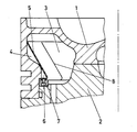
- FIG. 1 An embodiment is shown in the drawing, which shows a cooling oil channel in longitudinal section through a two-part piston.
- a steel piston crown 1 is attached to an aluminum piston lower part 2 by fastening means, not shown. Cooling oil flows through the annular space 3.
- a slotted flexible ring 5 is introduced to shield a partial area 4 of the annular space 3. This ring 5 is via screws 6 on an intermediate ring 7 from z. B. steel fit between the piston crown 1 and the lower piston part 2.
- the parting line 8 of the slotted ring 5 can be welded subsequently.
- the ring 5 is preformed in such a way that after its assembly, it rests firmly against the piston wall region to be covered at its upper free end.
Landscapes
- Engineering & Computer Science (AREA)
- Chemical & Material Sciences (AREA)
- Combustion & Propulsion (AREA)
- Mechanical Engineering (AREA)
- General Engineering & Computer Science (AREA)
- Physics & Mathematics (AREA)
- Fluid Mechanics (AREA)
- Pistons, Piston Rings, And Cylinders (AREA)
Abstract
Description
- Die Erfindung betrifft einen mehrteiligen Kolben für Verbrennungsmotoren nach dem Oberbegriff des Patentanspruchs.
- Mit Kühlöl beaufschlagte Flächen in dem Kühlölkanal eines Kolbens lokal gegen die Wirkung des Kühlöls zu isolieren ist z. B. aus DE-OS 29 30 079 und DE-G 81 32 778 bekannt. In beiden Fällen wird die Isolierung durch die Ausbildung eines Hohlraumes mit Hilfe eines zusätzlich in den Kolben einzubringenden Blechringes erreicht. Dabei ist die Ausführung nach dem DE-G 81 32 778 auf Fälle ausgerichtet, in denen die abzudeckende Fläche in einem hinterschnittenen Ringraum liegt. In diesem Fall muß nämlich der einzubringende Blechring während der Montage verformbar sein, da er sonst in die Hinterschnitträume nicht eingebracht werden kann. Die Verformbarkeit kann dabei z. B. durch ein achsiales Schlitzen des Ringes erfolgen. Bei der Lösung nach dem genannten Gebrauchsmuster besteht eine Schwierigkeit jedoch darin, den eingebrachten Blechring an dem entsprechenden Kolbenteil betriebssicher zu fixieren, ohne durch die Art der Fixierung das mechanische Verhalten des betreffenden Kolbenteiles unter Betriebslast negativ zu beeinflussen. Eine solche negative Beeinflussung ergibt sich z. B. durch ein Anschweißen des Blechringes an das betreffende Kolbenteil. Durch eine an dem oberen und unteren Ende des einzubringenden Blechringes vorgenommene feste Verbindung mit dem betreffenden Kolbenteil kann auch das rechnerisch vorbestimmte elastische Verhalten dieses Kolbenteiles unter Betriebsbedingungen negativ beeinflußt werden.
- Hiervon ausgehend liegt der Erfindung die Aufgabe zugrunde, für einen zur Isolierung bestimmter Teilbereiche einzubringenden Blechring eine in jeder Hinsicht betriebssichere und einfache Fixierung innerhalb der zu verbindenden Kolbenteile zu finden, bei der weder die Werkstoffeigenschaften des betreffenden Kolbenteiles, noch dessen Materialeigenschaften durch die Art der Verbindung des einzubringenden Ringes negativ beeinflußt werden können.
- Gelöst wird diese Aufgabe gemäß den Merkmalen des Patentanspruchs durch die Verwendung eines zusätzlichen Zwischenringes, der zwischen den zu verbindenden Kolbenteilen im Kühl- ölkanalbereich eingeklemmt ist und an den der in den Kühlölkanal einzubringende Ring zerstörungsfrei lösbar angebunden werden kann.
- Eine zweckmäßige Art der Verbindung kann z. B. dadurch erreicht werden, daß der einzubringende Ring an dem Zwischenring mit Schrauben befestigt ist. Die Schrauben werden dann an der Seite des Zwischenringes eingeschraubt, die von dem Inneren des Kühlölkanals aus gesehen nach außen weist.
- Ein Ausführungsbeispiel ist in der Zeichnung dargestellt, die einen Kühlölkanal im Längsschnitt durch einen zweiteiligen Kolben zeigt.
- Ein Stahl-Kolbenboden 1 ist durch nicht dargestellte Befestiqunqsmittel auf einem Aluminiumkolbenunterteil 2 angebracht. Durch den Ringraum 3 strömt Kühlöl. Zur Abschirmung eines Teilbereiches 4 des Ringraumes 3 ist ein geschlitzter biegsamer Ring 5 eingebracht. Dieser Ring 5 ist über Schrauben 6 an einem Zwischenring 7 aus z. B. Stahl passungsgenau zwischen dem Kolbenboden 1 und dem Kolbenunterteil 2 eingeklemmt. Die Trennfuge 8 des geschlitzten Ringes 5 kann nachträglich verschweißt werden. Der Ring 5 ist so vorgeformt, daß er nach seiner Montage an seinem oberen freien Ende fest an dem abzudeckenden Kolbenwandbereich anliegt.
Claims (1)
- Mehrteiliger Kolben für Verbrennungsmotoren mit in einem Verbindungsbereich in der Nähe der Kolbenringnuten angeordnetem geschlossenen Kühlölkanal (3), in dem zur Wärmeisolation Teilbereiche (4) durch mindestens eine Ring-(5) Einlage abgetrennt sind, dadurch gekennzeichnet, daß diese Ring- (5) Einlagen mit einem oder jeweils einem zwischen miteinander in Verbindung stehenden Kolbenteilen eingeklemmten zusätzlichen Zwischenring (7) zerstörungsfrei lösbar verbunden sind.
Applications Claiming Priority (2)
| Application Number | Priority Date | Filing Date | Title |
|---|---|---|---|
| DE3338809 | 1983-10-26 | ||
| DE3338809 | 1983-10-26 |
Publications (3)
| Publication Number | Publication Date |
|---|---|
| EP0141992A2 true EP0141992A2 (de) | 1985-05-22 |
| EP0141992A3 EP0141992A3 (en) | 1986-05-21 |
| EP0141992B1 EP0141992B1 (de) | 1988-05-04 |
Family
ID=6212749
Family Applications (1)
| Application Number | Title | Priority Date | Filing Date |
|---|---|---|---|
| EP84111624A Expired EP0141992B1 (de) | 1983-10-26 | 1984-09-28 | Mehrteiliger Kolben für Verbrennungsmotoren mit teilisoliertem Kühlölkanal |
Country Status (3)
| Country | Link |
|---|---|
| EP (1) | EP0141992B1 (de) |
| JP (1) | JPS60111048A (de) |
| DE (1) | DE3470908D1 (de) |
Cited By (3)
| Publication number | Priority date | Publication date | Assignee | Title |
|---|---|---|---|---|
| EP1288464A3 (de) * | 2001-08-30 | 2003-08-20 | Caterpillar Inc. | Kolbenzusammenbau für eine Freikolbenbrennkraftmaschine |
| WO2013156442A1 (de) * | 2012-04-18 | 2013-10-24 | Mahle International Gmbh | Kolben für eine brennkraftmaschine |
| WO2017087433A1 (en) * | 2015-11-18 | 2017-05-26 | Federal-Mogul Corporation | Piston providing for reduced heat loss using cooling media |
Family Cites Families (2)
| Publication number | Priority date | Publication date | Assignee | Title |
|---|---|---|---|---|
| GB348084A (en) * | 1928-11-09 | 1931-04-28 | Hugo Junkers | Improvements in and relating to pistons for engines |
| DE3017787C2 (de) * | 1980-05-09 | 1987-01-29 | Klöckner-Humboldt-Deutz AG, 5000 Köln | Mehrteiliger Kolben für Brennkraftmaschinen |
-
1984
- 1984-09-28 DE DE8484111624T patent/DE3470908D1/de not_active Expired
- 1984-09-28 EP EP84111624A patent/EP0141992B1/de not_active Expired
- 1984-10-25 JP JP59223132A patent/JPS60111048A/ja active Pending
Cited By (5)
| Publication number | Priority date | Publication date | Assignee | Title |
|---|---|---|---|---|
| EP1288464A3 (de) * | 2001-08-30 | 2003-08-20 | Caterpillar Inc. | Kolbenzusammenbau für eine Freikolbenbrennkraftmaschine |
| WO2013156442A1 (de) * | 2012-04-18 | 2013-10-24 | Mahle International Gmbh | Kolben für eine brennkraftmaschine |
| US9726109B2 (en) | 2012-04-18 | 2017-08-08 | Mahle International Gmbh | Piston for an internal combustion engine |
| WO2017087433A1 (en) * | 2015-11-18 | 2017-05-26 | Federal-Mogul Corporation | Piston providing for reduced heat loss using cooling media |
| US10294887B2 (en) | 2015-11-18 | 2019-05-21 | Tenneco Inc. | Piston providing for reduced heat loss using cooling media |
Also Published As
| Publication number | Publication date |
|---|---|
| DE3470908D1 (en) | 1988-06-09 |
| EP0141992A3 (en) | 1986-05-21 |
| JPS60111048A (ja) | 1985-06-17 |
| EP0141992B1 (de) | 1988-05-04 |
Similar Documents
| Publication | Publication Date | Title |
|---|---|---|
| DE4038509C2 (de) | ||
| DE3032253C2 (de) | Verbrennungsmotor, insbesondere Dieselmotor | |
| DE2918294A1 (de) | Zylinder fuer ein pneumatikelement | |
| DE2638335C2 (de) | Zylinderlaufbüchse für Kolben- Brennkraftmaschinen | |
| EP0099873A2 (de) | Zylindrischer Drehschieber mit Abdichtung für Kolbenmotoren | |
| DE19636089C2 (de) | Fixiereinrichtung zur Fixierung einer Baueinheit von Kolben, Pleuel und Zylinderbüchse vor der Montage oder Demontage bei einer Brennkraftmaschine | |
| CH615980A5 (de) | ||
| DE2200818A1 (de) | Einlass- und Auslassleitungen fuer einen Verbrennungsmotor sowie deren Stroemungskanaele | |
| DE3107461C2 (de) | Gehäuseblock für Hubkolben-Brennkraftmaschinen insbesondere Dieselmotoren | |
| EP0141992B1 (de) | Mehrteiliger Kolben für Verbrennungsmotoren mit teilisoliertem Kühlölkanal | |
| EP0204687A2 (de) | Zweitakt-Brennkraftmaschine | |
| EP0709557B1 (de) | Vorrichtung zum Einblasen von Luft in ein Abgasrohr | |
| DE8330717U1 (de) | Mehrteiliger kolben fuer verbrennungsmotoren mit teilisoliertem kuehloelkanal | |
| DE2757548C2 (de) | Flüssigkeitsgekühlter Zweitaktmotor | |
| DE4026384C1 (de) | ||
| EP0327848B1 (de) | Luftansaugrohr für eine Brennkraftmaschine | |
| DE10225573B4 (de) | Zweitaktmotor und Verfahren zu dessen Herstellung | |
| DE2733302A1 (de) | Abgaskasten fuer mehrzylinder-brennkraftmaschinen, insbesondere fuer kraftfahrzeuge | |
| DE600604C (de) | Laengsgeteilter Zylinder mit auswechselbarer Laufbuechse fuer luftgekuehlte Zweitaktbrennkraftmaschinen | |
| DE1020490B (de) | Auspufftopf fuer Brennkraftmaschinen, insbesondere von Kraftfahrzeugen | |
| DE3331664C2 (de) | ||
| DE2718162A1 (de) | Zweitaktbrennkraftmaschine | |
| DE767670C (de) | Zweitaktbrennkraftmaschine mit Hochspuelung und vom Kolben gesteuerten Ein- und Auspuffschlitzen | |
| EP0290425B1 (de) | Schalldämpfer für Verbrennungskraftmaschinen | |
| DE102019134662A1 (de) | Lagerdeckel |
Legal Events
| Date | Code | Title | Description |
|---|---|---|---|
| PUAI | Public reference made under article 153(3) epc to a published international application that has entered the european phase |
Free format text: ORIGINAL CODE: 0009012 |
|
| AK | Designated contracting states |
Designated state(s): DE FR GB IT |
|
| RTI1 | Title (correction) | ||
| PUAL | Search report despatched |
Free format text: ORIGINAL CODE: 0009013 |
|
| AK | Designated contracting states |
Kind code of ref document: A3 Designated state(s): DE FR GB IT |
|
| 17P | Request for examination filed |
Effective date: 19861004 |
|
| 17Q | First examination report despatched |
Effective date: 19870429 |
|
| GRAA | (expected) grant |
Free format text: ORIGINAL CODE: 0009210 |
|
| AK | Designated contracting states |
Kind code of ref document: B1 Designated state(s): DE FR GB IT |
|
| PG25 | Lapsed in a contracting state [announced via postgrant information from national office to epo] |
Ref country code: IT Free format text: LAPSE BECAUSE OF FAILURE TO SUBMIT A TRANSLATION OF THE DESCRIPTION OR TO PAY THE FEE WITHIN THE PRESCRIBED TIME-LIMIT;WARNING: LAPSES OF ITALIAN PATENTS WITH EFFECTIVE DATE BEFORE 2007 MAY HAVE OCCURRED AT ANY TIME BEFORE 2007. THE CORRECT EFFECTIVE DATE MAY BE DIFFERENT FROM THE ONE RECORDED. Effective date: 19880504 Ref country code: FR Free format text: THE PATENT HAS BEEN ANNULLED BY A DECISION OF A NATIONAL AUTHORITY Effective date: 19880504 |
|
| REF | Corresponds to: |
Ref document number: 3470908 Country of ref document: DE Date of ref document: 19880609 |
|
| EN | Fr: translation not filed | ||
| GBV | Gb: ep patent (uk) treated as always having been void in accordance with gb section 77(7)/1977 [no translation filed] | ||
| PG25 | Lapsed in a contracting state [announced via postgrant information from national office to epo] |
Ref country code: GB Free format text: LAPSE BECAUSE OF NON-PAYMENT OF DUE FEES Effective date: 19881123 |
|
| PLBE | No opposition filed within time limit |
Free format text: ORIGINAL CODE: 0009261 |
|
| STAA | Information on the status of an ep patent application or granted ep patent |
Free format text: STATUS: NO OPPOSITION FILED WITHIN TIME LIMIT |
|
| 26N | No opposition filed | ||
| PGFP | Annual fee paid to national office [announced via postgrant information from national office to epo] |
Ref country code: DE Payment date: 19911017 Year of fee payment: 8 |
|
| PG25 | Lapsed in a contracting state [announced via postgrant information from national office to epo] |
Ref country code: DE Effective date: 19930602 |