EP0140451A2 - Behandlungseinrichtung für eine Wand, z.B. eine Schiffswand - Google Patents
Behandlungseinrichtung für eine Wand, z.B. eine Schiffswand Download PDFInfo
- Publication number
- EP0140451A2 EP0140451A2 EP84201544A EP84201544A EP0140451A2 EP 0140451 A2 EP0140451 A2 EP 0140451A2 EP 84201544 A EP84201544 A EP 84201544A EP 84201544 A EP84201544 A EP 84201544A EP 0140451 A2 EP0140451 A2 EP 0140451A2
- Authority
- EP
- European Patent Office
- Prior art keywords
- segment
- wall
- segments
- carrier
- bearing support
- Prior art date
- Legal status (The legal status is an assumption and is not a legal conclusion. Google has not performed a legal analysis and makes no representation as to the accuracy of the status listed.)
- Withdrawn
Links
Images


Classifications
-
- B—PERFORMING OPERATIONS; TRANSPORTING
- B63—SHIPS OR OTHER WATERBORNE VESSELS; RELATED EQUIPMENT
- B63B—SHIPS OR OTHER WATERBORNE VESSELS; EQUIPMENT FOR SHIPPING
- B63B59/00—Hull protection specially adapted for vessels; Cleaning devices specially adapted for vessels
- B63B59/06—Cleaning devices for hulls
Definitions
- the invention relates to a device for treating a wall, for example, a ship's wall comprising a supporting device having a head movable along the wall and an elongate carrier connected with the head and carrying processing members.
- the elongate carrier for the processing members may be a spraying boom.
- the processing members in the form of spraying heads can spray water under very high pressure onto a ship's wall in order to remove fouling and loose paint.
- the processing members may also be grit blasting heads or paint sprayers.
- a flat or slightly curved ship's wall can be treated stripwise. It has been found that in the case of stronger curves of the wall, for example at the area of the stem and stern of a ship and on the bottom side the known device with an elongate carrier for the processing members does no longer operate effectively.
- the invention has for its object to provide a device of the kind set forth in the preamble by means of which even strongly curved walls can be effectively treated.
- the carrier comprises a basic segment connected with the head and a plurality of relatively pivotable, elongate segments forming a chain with the basic segment on at least one side of the basic segment and in that moving and guiding means are provided for the pivotable movement of the segments relative to one another, the guiding means comprising a bearing support rigidly secured to the basic segment, a bearing support rigidly secured to the second segment, viewed from the basic segment and a coupling rod pivotally connected with said bearing supports, whilst the coupling rod and the first segment define a non-parallelogram-shaped, four bar linkage and in that the moving means comprise a hydraulic jack arranged between a bearing support rigidly secured to the basic segment and a bearing support rigidly secured to one of the plurality of segments.
- the processing members operate satisfactorily only within a limited, varying distance from the wall to be treated.
- the device according to the invention it is ensured that the optimum distance for the processing members can be maintained throughout the length of the elongate carrier since the segments can appropriately match the curvature of the wall to be treated.
- the movement of the second segment from the basic segment is coupled by the coupling rod with the movement of the first segment so that the two segments can be moved by means of only one hydraulic jack.
- the guiding means comprise a bearing support rigidly secured to each segment after the second segment, a bearing support secured to the pre-preceding segment and a coupling rod pivotally connected with said bearing supports, the coupling rod and the intermediate segment defining a non-parallelogram-shaped four bar linkage.
- the coupling rod crosses each time the intermediate segment extending over substantially the same distance.
- the segments can advantageously assume the shape of a circular arc with acceptable approximation. Since the curves of walls such as ship's walls can be approached by a series of parts of a circle, this embodiment is particularly suitable.
- the end of the last segment is preferably provided with a sensor coupled with the moving means.
- This sensor detects the distance from the wall to be treated. As soon as the distance becomes too small, the moving means are actuated so that the segments are bent away from the wall. If the distance becomes too large, the moving means move the segments towards the wall. In this way by a simple coupling between the sensor and the moving means an automatic adaptation of the carrier to the curvature of the wall to be treated can be obtained.
- a hood is connected with the carrier in accordance with the invention, said hood leaving the carrier free only with respect to the wall.
- this hood is preferably designed in the form of bellows provided at the edges with brush elements. The bellows can follow the movements of the carrier and ensure a satisfactory seal with the wall.
- the hood is made from chrome leather which has the suitable properties to enable the use in a bellow-shaped hood as well as to withstand the loads occurring in operation and the substances employed thereto.
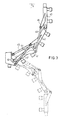
- the device 1 comprises a supporting device 2, an arm 4 and at the end of said arm a movable head 3 shown in Fig. 1.
- the head 3 is pivotally connected with the arm 4 by means of a bearing 8.
- the angular position of the head 3 with respect to the arm 4 is determined by a hydraulic jack 6, which engages a pivotal shaft 5 of the head 3.
- the supporting device 2 can reciprocately move the head 3 in the direction of the double arrow 27 and also in a direction perpendicular thereto.
- a carrying plate 30 On the head 3 is rotatably mounted a carrying plate 30 by means of a bearing 7.
- the carrying plate 30 can be turned with the aid of a jack 9 arranged between said plate and an extension arm 31 of the head between the position shown in Fig. 1 and a position turned through 90° with respect to the former.
- the carrying plate 30 is provided with a console 10 in which a holder 32 is pivotally arranged by means of a bearing 11.
- the first segment 12 of the carrier 35 is rigidly secured to the holder 32.
- the carrier 35 comprises the basic segment 12 connected with the head 3 and a plurality of elongate segments 13, 14, 15, 16 pivotally connected with said basic segment 12.
- the segments 13 to 16 are pivotally interconnected to form a chain with one another and with the basic segment.
- the segment 13 is connected with the basic segment 12 by means of a hinge 23, whereas the segment 14 is connected with the segment 13 by means of a hinge 22.
- the segments 15 and 16 are pivotally connected with one another and with the basic segment 12 on the other side of the basic segment 12.
- Fig. 1 shows that the segments 13 to 16 are provided with spray nozzles 17 capable of spraying water supplied under high pressure through a duct 19 in the form of a jet 18 onto a wall.
- This wall is not shown in the Figure.
- the supply of pressurized water to the spray nozzle 17 may be performed in various ways, for example, through separate ducts or through a duct incorporated in the carrier. This mode of supply does not form part of the present invention, however, and will, therefore, not be further discussed.
- the segments 13 to 16 can relatively turn in a programmed way with the aid of the guiding means 20 and the moving means 21.
- the guiding means 20 for the segments 13, 14 on the underside of the basic segment 12 comprise a bearing support 25 rigidly secured to the basic segment 12, a bearing support 24 rigidly secured to the second segment 14 and a coupling rod 26 pivotally connected with said bearing supports 25, 24.
- the relative movements of the pivotable segments will be discussed in detail with reference to Figs. 2 ff.
- Fig. 1 furthermore shows that the holder 32 is provided with an arm 33, between the free end of which and the carrying plate 30 is arranged a jack 34.
- a jack 34 By sliding the jack 34 in or out the carrier 35 connected with the holder 32 can be turned about the axis of a bearing 11 so that the nozzles 17 can be set at an appropriate angle to the wall to be treated.
- the console 10 is furthermore provided with extension arms 28, which carry wheels 29 at their projecting ends.
- the rotary axis of these wheels 29 is parallel to the longitudinal axis of the carrier 35.
- the supporting device 2 can urge the assembly of carrier 35 and head 3 with the wheels 29 against the wall to be treated.
- the processing members formed by the spray nozzles 17 can treat a wall in strips.
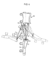
- Fig. 2 shows that the coupling rod 26 constitutes with the first segment 13 a non-parallelogram-shaped four bar linkage. It is thus ensured that each pivot position of the first segment 13 with respect to the basic segment 12 is associated with a given pivot position of the second segment 14 with respect to the first segment 13. In other terms the movement of the second segment 14 is coupled with the movement of the first segment 13.
- the moving means 21 comprise a jack engaging the bearing support 24.
- Fig. 2 shows the outermost retired position of the carrier by solid lines, whereas the outermost advanced position is indicated by broken lines.
- the coupling rod 26 crosses the intermediate segment covering substantially the same distance, whilst the distances of the bearing supports 25, 24 from the centre line of the associated segments 12 and 14 respectively are substantially the same.
- Fig. 2 shows that in this way the segments 13, 14 together with the basic segment 12 can occupy a position approaching the shape of a circular arc both in the retired and in the advanced state.
- the device 1 comprises a carrier 35 comprising a basic segment 12 and two further segments 13, 14 and 15, 16 respectively on each side of the basic segment 12.
- the number of segments on both sides of the basic segment may be different and need not be equal to two.
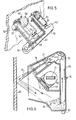
- Fig. 3 shows an embodiment of the invention in which on one side of the basic segment 40 three further segments 41, 42, 43 are arranged.
- the constructions of the basic segment 40 and the first segment 41 and of the second segment 42 together with the guiding means including the coupling rod 44 and the moving means including the jack 45 are mainly identical to those of the embodiment shown in Figs. 1 and 2.
- the third segment 43 is pivotally connected with the end of the second segment 42.
- the third segment 43 comprises a bearing support 48, whilst the first segment 41 is provided with a corresponding bearing support 47. Between these bearing supports is arranged a coupling rod 46.
- the coupling rod 46 constitutes together with the second segment 42 a non-parallelogram-shaped four bar linkage.
- this four bar linkage has the same dimensions as the four bar linkage formed by the coupling rod 44 and the first segment 41.
- the third segment 43 moves in dependence on the first segment 41.
- all segments 41 to 43 can be moved with the aid of a single jack 45 between the retired position shown in Fig. 3 by solid lines and the advanced position indicated by broken lines.
- the distances of the bearing supports 47 and 48 from the centre line of the associated segments 41 and 43 respectively are substantially the same so that a substantially symmetrical movability with respect to the stretched position is obtained.
- the bearing support 53 for the coupling rod 56 is provided with a plurality of points of application 54.
- the Figure shows two outermost positions by broken lines in the situation in which the coupling rod engages the point of application 54 lying nearest the centre line of the segment 52. It is apparent that the second segment 52 in the extreme positions has turned with respect to the first segment 51 further than the first segment 51 has turned with respect to the basic segment 57.
- each segment may comprise at least one mounting support for releasably mounting a processing member.
- Fig. 5 shows a segment 60 of a carrier designed in the way described in the foregoing.
- the segment 60 is connected by means of a hinge at one of its ends with a further segment (not shown) of the carrier.
- the guiding and moving means for this segment 60 are omitted for the sake of clarity.
- the segment 60 is provided with two mounting supports 62, 63. On these supports 62, 63 are mounted holders 65 with the aid of bolts 64. These holders 65 form part of brush devices 66.
- the brush devices 66 furthermore comprise a brush 68 journalled in the end of the holders 65 and driven by a hydromotor 67.
- the hydromotor 67 is connected with inlet and outlet ducts 69 for hydraulic fluid by pressure to the motors 67.
- the brushes 68 may be steel wire brushes for removing rust and dirt and for polishing the wall 59.
- the brushes 68 may also be fibre brushes for cleaning the wall 59.
- Fig. 6 is a side elevation of a segment 70 of a device embodying the invention.
- This segment 70 is connected by a hinge tag 71 with an adjacent segment of the carrier.
- the segment 70 of this carrier is also provided with a mounting support 72.
- On this support 72 is mounted a grit blasting member 74 by means of bolts 73.
- the grit blasting member 74 comprises a hood 75, in the top end of which is mounted a supply blade wheel 76 which is rotatably driven.
- Below the hood 75 comprises a stock reservoir 81 for grit. From this reservoir 81 grit is supplied to the blade wheel 76 by means of air supplied through a duct 82.
- the grit is fed by the blade wheel 76 via the guide plates 77 to high-speed conveyor belts 78. These conveyor belts 78 project the grit with high speed in a jet 79 against the wall 80. From the wall 80 the reverberating grit with the removed dirt falls back into the hood 75 and is collected in the reservoir 81, from where it can be used again.
- the brush devices 66 and the grit blasting members 74 are examples of processing members which can be arranged on a carrier embodying the invention. In themselves they do not form part of the present invention, but they only serve as examples of processing members releasably mounted on the carrier.
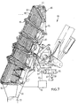
- Fig. 7 shows a device 84 embodying the invention which mainly corresponds with the device 1 of Fig. 1.
- the device 84 comprises a carrier 85.
- the carrier 85 has connected with it a hood 86 leaving it free only towards the wall (not shown).
- the hood 86 has the form of bellows 87 provided at the edges with brush elements 88. Owing to the bellows effect the brush elements 88 at the edge of the bellows 87 are held in contact with the wall to be treated when the carrier 85 of the device 84 is moved along said wall.
- the hood collects the material released by the processing members and dirt removed from the wall.
- the hood 86 collects sprayed water and when the processing members are formed by grit blasting members of the kind of Fig. 6 or of another kind any released grit is collected. Moreover, the material loosened from the wall, for example, paint residues, is collected. When the wall to be treated is a ship's wall, the latter is very important since the paint used for ship's walls is usually poisonous to avoid fouling. The hood 86 ensures that undesirable materials will not get into the environment.
- the material collected in the hood 86 is conducted away through a funnel 90 to a drain tube 91.
- the bellows 86 have folds 89 at the level of the hinges of the segments. Thus the bellows 86 can follow the relative movements of the segments and intimately engage by the brush elements 88 the curved walls.
- the device 84 is provided with sensors 92, which are arranged in this embodiment at the ends of the carrier 85. These sensors 92 detect the distance from the wall to be treated. As is shown quite schematically in Fig. 7 the signal from the sensors 92 can be directly used for controlling the moving means formed by the jacks 100 and 101. Each sensor 92 co-operates with the associated jack. Fig. 7 only shows the control of the jack 100. The control of the jack 101 is identical.
- the signal of the sensor 92 which may comprise a terminal switch or an approach switch, is applied to a control-device 93.
- a corresponding control-signal is given off by the control-device 93 through the control-conductor 95.
- the control-conductor 95 is connected with the control-member 94 of a control-valve 96 designed in the form of a three-position valve.
- the valve 96 can connect the hydraulic pressure duct 98 (shown schematically) and the drain duct 97 with the hydraulic ducts 99 of the jack 100.
- the signal applied through the control-conductor 95 to the control-member 94 is such that the valve 96 is shifted to the right.
- pressurized hydraulic fluid is fed from the duct 98 to the front of the jack 100, which thus slips in and the distance of the associated segments and hence of the sensor 92 from the wall becomes larger.
- the control- device 93 applies through the conductor 95 to the control-member 94 a signal such that the valve 96 shifts to the left so that the jack 100 slips out and the distance from the wall is reduced.
- control-devices for the lower segments of the carrier 85 can operate completely independently of the control-devices for the upper segments of the carrier 85. In this way completely automatic adaptation of the relative positions of the segments of the carrier to the curvature of the wall to be treated is ensured.
- the supporting device need, therefore, be actuated so that the carrier 85 is moved in strips along the wall to be treated. Owing to the effect of the control-devices 93 the shape of the carrier 85 automatically follows the curvature of the wall to be treated.
- Figs. 1 and 7 show that the distance of the carrier from the wall to be treated is defined with the aid of guide wheels.
- the supporting device may also be designed so that the desired distance is maintained with the aid of contactless sensors. The effect of the sensors of the carriers remains the same.
- the processing members are formed by paint sprayers
- no brush elements can be used on the hood, which would remain in contact with the ship's wall.
- a hood is used, the dimensions of which are such that the edge remains at a small distance from the ship's wall.
- air containing the paint fog can be withdrawn through the outlet tube 91.
- the wall can be treated in any possible manner without polluting the environments.
Landscapes
- Chemical & Material Sciences (AREA)
- Engineering & Computer Science (AREA)
- Combustion & Propulsion (AREA)
- Mechanical Engineering (AREA)
- Ocean & Marine Engineering (AREA)
- Spray Control Apparatus (AREA)
- Details Or Accessories Of Spraying Plant Or Apparatus (AREA)
- Coating Apparatus (AREA)
- Ship Loading And Unloading (AREA)
Applications Claiming Priority (2)
| Application Number | Priority Date | Filing Date | Title |
|---|---|---|---|
| NL8303794 | 1983-11-03 | ||
| NL8303794A NL8303794A (nl) | 1983-11-03 | 1983-11-03 | Inrichting voor het behandelen van een wand, zoals een scheepswand. |
Publications (2)
| Publication Number | Publication Date |
|---|---|
| EP0140451A2 true EP0140451A2 (de) | 1985-05-08 |
| EP0140451A3 EP0140451A3 (de) | 1985-06-12 |
Family
ID=19842656
Family Applications (1)
| Application Number | Title | Priority Date | Filing Date |
|---|---|---|---|
| EP84201544A Withdrawn EP0140451A3 (de) | 1983-11-03 | 1984-10-25 | Behandlungseinrichtung für eine Wand, z.B. eine Schiffswand |
Country Status (3)
| Country | Link |
|---|---|
| EP (1) | EP0140451A3 (de) |
| JP (1) | JPS60114373A (de) |
| NL (1) | NL8303794A (de) |
Cited By (2)
| Publication number | Priority date | Publication date | Assignee | Title |
|---|---|---|---|---|
| CN110588914A (zh) * | 2019-08-13 | 2019-12-20 | 浙江海洋大学 | 船舶外表面除锈机器人 |
| CN112571301A (zh) * | 2020-12-24 | 2021-03-30 | 华南理工大学 | 一种磨料水射流喷头 |
Families Citing this family (3)
| Publication number | Priority date | Publication date | Assignee | Title |
|---|---|---|---|---|
| JPH0415330Y2 (de) * | 1985-12-12 | 1992-04-07 | ||
| AT507564B1 (de) | 2009-01-12 | 2010-06-15 | Hoerbiger Kompressortech Hold | Dichtanordnung zur abdichtung einer kolbenstange eines kolbenkompressors |
| JP7355516B2 (ja) * | 2019-03-29 | 2023-10-03 | 住友重機械マリンエンジニアリング株式会社 | 塗装装置、及び塗装方法 |
Family Cites Families (4)
| Publication number | Priority date | Publication date | Assignee | Title |
|---|---|---|---|---|
| US2590400A (en) * | 1949-06-06 | 1952-03-25 | Helen Gollnick | Tree sprayer |
| GB1112960A (en) * | 1965-12-03 | 1968-05-08 | Jan Vadseth | Arrangement for cleaning a ship's hull of marine growth |
| US4353505A (en) * | 1980-08-04 | 1982-10-12 | Leon Kinder | Spraying apparatus |
| NL8004610A (nl) * | 1980-08-14 | 1982-03-16 | Stork Serv Bv | Dokinrichting. |
-
1983
- 1983-11-03 NL NL8303794A patent/NL8303794A/nl not_active Application Discontinuation
-
1984
- 1984-10-25 EP EP84201544A patent/EP0140451A3/de not_active Withdrawn
- 1984-11-02 JP JP59232276A patent/JPS60114373A/ja active Pending
Cited By (2)
| Publication number | Priority date | Publication date | Assignee | Title |
|---|---|---|---|---|
| CN110588914A (zh) * | 2019-08-13 | 2019-12-20 | 浙江海洋大学 | 船舶外表面除锈机器人 |
| CN112571301A (zh) * | 2020-12-24 | 2021-03-30 | 华南理工大学 | 一种磨料水射流喷头 |
Also Published As
| Publication number | Publication date |
|---|---|
| JPS60114373A (ja) | 1985-06-20 |
| EP0140451A3 (de) | 1985-06-12 |
| NL8303794A (nl) | 1985-06-03 |
Similar Documents
| Publication | Publication Date | Title |
|---|---|---|
| US4677998A (en) | Method and apparatus for removing pipe coatings | |
| US8900037B2 (en) | Grinding device for machine based grinding of rotor blades for wind energy systems | |
| CA1270147A (en) | Washing device for impression cylinders | |
| EP0046319A1 (de) | Dockeigene Schiffskörper-Behandlungsanlage | |
| US20120152281A1 (en) | Cleaning vehicle and method for parabolic trough solar collectors | |
| PL173855B1 (pl) | Urządzenie do oczyszczania przedmiotów w ruchu | |
| EP0165911B1 (de) | Verfahren und Robotplattform zum Waschen, Sandstrahlen und Streichen in einem Schiffsdock | |
| US5725003A (en) | Vehicle washing apparatus | |
| US4985957A (en) | Wheel washing apparatus and method | |
| EP0140451A2 (de) | Behandlungseinrichtung für eine Wand, z.B. eine Schiffswand | |
| US3532070A (en) | Treatment vehicle for highway guard structures | |
| US5123136A (en) | Wheel washing apparatus | |
| US6000095A (en) | Dual port air blower for drying vehicles | |
| CA2124310A1 (en) | Vehicle washing system | |
| US5052629A (en) | Wheel washing apparatus | |
| GB2050876A (en) | Spray painting or cleaning vehicle | |
| CN208146284U (zh) | 循环型砂型铸造铸件用喷涂装置 | |
| EP0899021A1 (de) | Lackiervorrichtung | |
| EP1196321B1 (de) | Vorrichtung zur aussenreinigung von booten | |
| US5493795A (en) | Ballast regulator having improved track cleaning means | |
| JPS6099791A (ja) | 船渠内で用いる機械的船底処理装置 | |
| EP0256699A2 (de) | Reinigungsvorrichtung eines Rumpf-Innenraums | |
| JPS6025169B2 (ja) | 洗浄装置 | |
| US20210107138A1 (en) | Air Gap Magnetic Mobile Robot with Adjustable Headpiece | |
| WO1987000724A1 (en) | Arrangement in an irrigation system |
Legal Events
| Date | Code | Title | Description |
|---|---|---|---|
| PUAI | Public reference made under article 153(3) epc to a published international application that has entered the european phase |
Free format text: ORIGINAL CODE: 0009012 |
|
| PUAL | Search report despatched |
Free format text: ORIGINAL CODE: 0009013 |
|
| AK | Designated contracting states |
Designated state(s): DE GB NL |
|
| AK | Designated contracting states |
Designated state(s): DE GB NL |
|
| STAA | Information on the status of an ep patent application or granted ep patent |
Free format text: STATUS: THE APPLICATION IS DEEMED TO BE WITHDRAWN |
|
| 18D | Application deemed to be withdrawn |
Effective date: 19860212 |
|
| RIN1 | Information on inventor provided before grant (corrected) |
Inventor name: VAN DEN BROEK, BERNARDUS CORNELIS |