EP0140374A2 - Vorrichtung für Hochgeschwindigkeitsaufnahmen mittels stimulierbarer Phosphorfolien sowie lichtdichte Taschen dafür - Google Patents
Vorrichtung für Hochgeschwindigkeitsaufnahmen mittels stimulierbarer Phosphorfolien sowie lichtdichte Taschen dafür Download PDFInfo
- Publication number
- EP0140374A2 EP0140374A2 EP84113083A EP84113083A EP0140374A2 EP 0140374 A2 EP0140374 A2 EP 0140374A2 EP 84113083 A EP84113083 A EP 84113083A EP 84113083 A EP84113083 A EP 84113083A EP 0140374 A2 EP0140374 A2 EP 0140374A2
- Authority
- EP
- European Patent Office
- Prior art keywords
- stimulable phosphor
- image recording
- sheet
- lighttight
- lighttight envelope
- Prior art date
- Legal status (The legal status is an assumption and is not a legal conclusion. Google has not performed a legal analysis and makes no representation as to the accuracy of the status listed.)
- Granted
Links
Images


Classifications
-
- G—PHYSICS
- G03—PHOTOGRAPHY; CINEMATOGRAPHY; ANALOGOUS TECHNIQUES USING WAVES OTHER THAN OPTICAL WAVES; ELECTROGRAPHY; HOLOGRAPHY
- G03B—APPARATUS OR ARRANGEMENTS FOR TAKING PHOTOGRAPHS OR FOR PROJECTING OR VIEWING THEM; APPARATUS OR ARRANGEMENTS EMPLOYING ANALOGOUS TECHNIQUES USING WAVES OTHER THAN OPTICAL WAVES; ACCESSORIES THEREFOR
- G03B42/00—Obtaining records using waves other than optical waves; Visualisation of such records by using optical means
- G03B42/02—Obtaining records using waves other than optical waves; Visualisation of such records by using optical means using X-rays
- G03B42/021—Apparatus for direct X-ray cinematography
Definitions
- This invention relates to a high-speed image recording apparatus used for recording X-ray images of objects in stimulable phosphor sheets by sequentially projecting the X-ray images onto the stimulable phosphor sheets.
- This invention also relates to a lighttight envelope used for high-speed conveyance of the stimulable phosphor sheets in the high-speed image recording apparatus.
- High-speed image recording apparatuses have heretofore been used for angiography and the like.
- the high-speed image recording apparatuses record X-ray images of objects on many X-ray films by sequentially projecting the X-ray images onto the X-ray films.
- the apparatuses are suitable particularly for sequentially recording angiograms, which change from time to time, on many X-ray films when the diffusion speed of the contrast media is different among the objects.
- the X-ray film is used in the form sandwiched, for example, between two intensifying screens and housed in a flexible lighttight envelope.
- the high-speed image recording apparatus using a lighttight envelope in which an X-ray film is housed comprises a first film receiving section for receiving the unexposed lighttight envelopes, a conveyance mechanism for sequentially conveying the lighttight envelopes at high speeds from the first film receiving section to an image recording position where the X-ray films are exposed to X-rays passing through an object, and for sequentially conveying the exposed lighttight envelopes at high speeds from the image recording position, and a second film receiving section for receiving the exposed lighttight envelopes which are conveyed at high speeds from the image recording position.
- the object is positioned on the high-speed image recording apparatus.
- the lighttight envelope used in the high-speed image recording apparatus constituted as described above has a configuration for sufficiently shielding the X-ray film from light.
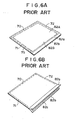
- Figure 6A is a perspective view showing an example of the lighttight envelope employed in the conventional high-speed image recording apparatus using an X-ray film
- Figure 6B is a perspective view showing the lighttight envelope of Figure 6A with the inlet opened.
- Sufficiently lighttight, black plastic sheets 82A and 82B are heat-sealed at their sides 70, 71 and 72 to form an envelope open at one side.
- the open side of the plastic sheet 82A continues into an opening edge portion 82a
- the open side of the plastic sheet 82B continues into an opening edge portion 82b.
- a face-to-face fastener 82c consisting of a tape provided with many fine hook-like fibers and a tape provided with many fine loop-like fibers is positioned so that the tapes extend on the inner surfaces of the opening edge portions 82a and 82b over the entire lengths thereof.
- the opening edge portions 82a and 82b are lighttightly engaged with each other by the face-to-face fastener 82c.
- an X - ray film 75 sandwiched between a pair of intensifying screens (not shown) is housed inside of the sealed sides 70, 71 and 72 and the face-to-face fastener 82c.
- the X-ray film 75 is handled and conveyed in a condition sufficiently shielded from light.
- the conventional lighttight envelope as described above houses the X-ray film 75 in the sufficiently lighttight condition and is loaded into the high-speed image recording apparatus.
- the face-to-face fastener 82c positioned at the opening edge portions 82a and 82b for securing sufficient lighttightness strongly closes the opening through which the X-ray film 75 is inserted into and removed from the lighttight envelope and since the area of the opening is small, insertion and removal of the X-ray film 75 are not easy to conduct.
- phosphors When certain kinds of phosphors are exposed to a radiation such as X-ray, a-rays, a-rays, y-rays cathode rays or ultra-violet rays, they store a part of the energy of the radiation. Then, when the phosphor which has been exposed to the radiation is exposed to stimulating rays such as visible light, light is emitted by the phosphor in proportion to the stored energy of the radiation. A phosphor exhibiting such properties is referred to as a stimulable phosphor.
- a stimulable phosphor sheet As disclosed in U.S. Patent No. 4,258,264 and Japanese Unexmined Patent Publication No. 56(1981)-11395, it has been proposed to use a stimulable phosphor in a radiation image recording and reproducing system. Specifically, a sheet provided with a layer of the stimulable phosphor (hereinafter referred to as a stimulable phosphor sheet) is first exposed to a radiation passing through an object to have a radiation image stored therein, and is then scanned with stimulating rays such as a laser beam which J ause it to emit light in the pattern of the stored image.
- stimulating rays such as a laser beam which J ause it to emit light in the pattern of the stored image.
- the light emitted by the stimulable phosphor sheet upon stimulation thereof is photoelectrically detected and converted to an electric image signal, which is processed as desired to reproduce a visible image on a recording medium such as a photographic film or on a display device such as a cathode ray tube (CRT).
- a recording medium such as a photographic film
- a display device such as a cathode ray tube (CRT).
- This radiation image recording and reproducing system using the stimulable phosphor sheet is advantageous over conventional radiography using an X-ray film and intensifying screens in that the radiation image can be recorded over a very wide range (latitude) of radiation exposure and further in that the electric signal used for reproducing the visible image can be freely processed to improve the image quality for ⁇ viewing, particularly for diagnostic purposes.
- the amount of light emitted upon stimulation after the radiation energy is stored in the phosphor varies over a very wide range in proportion to the amount of energy stored therein, it is possible to obtain an image having desired density regardless of the amount of exposure of the phosphor to the radiation by reading out the emitted light with an appropriate read-out gain and converting it to an electric signal to reproduce a visible image on a recording medium or a display device.
- the electric signal may further be processed as desired to obtain a radiation image suitable for viewing, particularly for diagnostic purposes. This is very advantageous in practical use.
- the high-speed image recording apparatus is suitable particularly for angiography. Therefore, if the high-speed image recording apparatus could be employed for the radiation image recording and reproducing system using the stimulable phosphor sheet, it would become possible to further improve the diagnostic efficiency and accuracy of angiograms. This would be very advantageous for medical diagnosis.
- the X-ray film Since the X-ray film is very sensitive to light, it must be maintained in the condition completely shielded from light from the stage prior to image recording up to development. Therefore, in the aforesaid high-speed image recording apparatus, the X-ray film is housed in a lighttight envelope having the configuration as described above, and is fed to the aforesaid first film receiving section in the condition completely shielded from light. After an image is recorded on the X-ray film, the X-ray film is removed from the aforesaid second film receiving section in the form housed in the lighttight envelope. Thereafter, the X-ray film is taken out of the lighttight envelope in a darkroom and is subjected to a development processing.
- the stimulable phosphor sheet need not be shielded from light before an X-ray image is recorded therein.
- the degree of light shielding for the stimulable phosphor sheet after an X-ray image is recorded thereon may be far lower than the degree of light shielding required for the X-ray film. Therefore, when the stimulable phosphor sheet is used in the high-speed image recording apparatus, it is not advantageous from the viewpoint of operating efficiency to employ the conventional lighttight envelope for the X-ray film having the configuration as described above directly as a lighttight envelope for the stimulable phosphor sheet.
- the stimulable phosphor sheet be used in the form housed in a comparatively simple lighttight envelope which is not so lighttight and which has a configuration facilitating insertion and removal of the stimulable phosphor sheet, or be used in the bare form without being housed in a lighttight envelope.
- the stimulable phosphor sheet In the case where the stimulable phosphor sheet is used in the form housed in a comparatively simple lighttight envelope or in the bare form for improving the operating efficiency, no problem arises as long as the stimulable phosphor sheet is inside of the high-speed image recording apparatus. However, a problem arises when the stimulable phosphor sheet is taken out of the high-speed image recording apparatus. Specifically, since the inside of the high-speed image recording apparatus is generally maintained in a semi-darkroom condition by a frame of the apparatus or the like, the X-ray image stored in the stimulable phosphor sheet is not adversely affected, i.e. the radiation energy stored theron is not dissipated by light, at the conveyance mechanism after the image recording position and at the second film receiving section.
- the stimulable phosphor sheet carrying the X-ray image stored thereon is taken out of the second film receiving section to the outside of the high-speed image recording apparatus, there arises a problem that the radiation energy stored may be partially or completely dissipated from a part or the entire surface of the stimulable phosphor sheet by ambient light. Accordingly, in the case where the stimulable phosphor sheet is used in the form housed in a comparatively simple lighttight envelope or in the bare form for improving the operating efficiency, it is necessary to provide the high-speed image recording apparatus with a mechanism for taking out the stimulable phosphor sheet carrying the X-ray image stored thereon in the condition shielded from ambient light.
- the primary object of the present invention is to provide a high-speed X-ray image recording apparatus wherein it is possible to use a stimulable phosphor sheet in the form not completely shielded from light and the operating efficiency for the stimulable phosphor sheet is improved.
- Another object of the present invention is to provide a high-speed X-ray image recording apparatus provided with a mechanism for taking a stimulable phosphor sheet in the form housed in a comparatively simple lighttight envelope or in the bare form out of the apparatus in the condition shielded from ambient light after an X-ray image is recorded on the stimulable phosphor sheet.
- the specific object of the present invention is to provide a lighttight envelope which has a comparatively simple light shielding function, which enables easy insertion and removal of a stimulable phosphor sheet, and which is suitable for use in the high-speed X-ray image recording apparatus.
- the present invention provides a high-speed image recording apparatus using stimulable phosphor sheets in which the stimulable phosphor sheets are sequentially moved to an image recording position for exposure to X-rays passing through an object, X-ray images of objects are sequentially projected onto said stimulable phosphor sheets to have the X-ray images stored thereon, and thereafter the exposed stimulable phosphor sheets are sequentially moved out of the image recording position,
- the high-speed image recording apparatus comprising a lighttight magazine for sequentially receiving and housing said stimulable phosphor sheets moved out of the image recording position, said magazine being releasably mounted on the main body of the high-speed image recording apparatus.
- the stimulable phosphor sheet need not be used in the form completely shielded from light. That is, it is possible to use the stimulable phosphor sheet in the form comparatively simply shielded from light or in the bare form. Therefore, handling of the stimulable phosphor sheet becomes very easy. Particularly in the case where a moveable grid is positioned between an object and the stimulable phosphor sheet at the image recording position and is moved in parallel with the stimulable phosphor sheet, it does not happen that the direct X-rays passing through the object are intercepted with respect to a particular portion of the stimulable phosphor sheet all the time during the exposure to X-rays.
- the present invention also provides a lighttight envelope for high-speed conveyance of a stimulable phosphor sheet, which is fabricated of a flexible light shielding material and has a size sufficient to house the stimulable phosphor sheet therein, the lighttight envelope comprising:
- close contact also embraces the case where the upper sheet and the lower sheet are joined together by folding.
- any means may be employed insofar as the upper sheet and the lower sheet can be easily engaged releasably with each other and prevented from naturally separating from each other.
- the envelope since the envelope has a wide opening, it is easy to insert a stimulable phosphor sheet into the envelope and to remove the stimulable phosphor sheet therefrom. Further, since the envelope exhibits lighttightness to a reasonable extent, it can be directly used in the high-speed image recording apparatus.
- the lighttight envelope also has the effect of protecting the surface of the stimulable phosphor sheet.
- FIG. 1 schematically shows an embodiment of the high-speed X-ray image recording apparatus in accordance with the present invention.
- a high-speed image recording apparatus 1 comprises a first receiving section 2 for receiving stimulable phosphor sheets before exposure to X-rays.
- the stimulable phosphor sheets may be in the form housed in comparatively simple lighttight envelopes or in the bare form.
- the high-speed image recording apparatus 1 also comprises a second receiving section 3 for receiving stimulable phosphor sheets after exposure to X-rays, and a conveyance mechanism for taking the stimulable phosphor sheets one by one out of the first receiving section 2, conveying them at high speeds up to an image recording position, and conveying the exposed stimulable phosphor sheets at high speeds to the second receiving section 3.
- a grid 4 for preventing scattered X-rays from impinging upon a stimulable phosphor sheet 5 sent to the image recording position is positioned to intervene between the 3 timulable phosphor sheet 5 and an object 20.
- the grid 4 should preferably be a moveable grid for movement in parallel with the stimulable phosphor sheet 5 in synchronization with exposure to X-rays.
- a plurality of unexposed stimulable phosphor sheets 5a, 5b, 5c, ... are loaded.
- the power of a motor 6 is transmitted to a conveying roller 8 via a clutch 7. Since the conveying roller 8 and guide rollers 9a to 9e are engaged with an endless conveyor belt 10, the conveyor belt 10 is moved in the direction of the arrow when the conveying roller 8 is rotated by the motor 6. Then, when a solenoid 11 is energized, a pressing piece 12 is activated to contact the conveyor belt 10 with the first stimulable phosphor sheet 5a among the stimulable phosphor sheets 5a, 5b, 5c, ... loaded in the first receiving section 2.
- the conveyor belt 10 releasably grasps, attracts or sucks the stimulable phosphor sheet 5a.
- the conveyor belt 10 may be provided with clamping claws for engagement with clamping pieces provided on the stimulable phosphor sheets, or may be provided with adhesive tapes.
- the conveyor belt 10 may be provided with female or male tapes of the face-to-face fastener type, and male or female tapes of this type may be provided on the stimulable phosphor sheets.
- the conveyor belt 10 may be constructed to magnetically attract the stimulable phosphor sheets one by one.
- a limit switch 13 detects the arrival of the stimulable phosphor sheet 5, and the detection signal of the limit switch 13 is sent to a control section 14' in the apparatus.
- the clutch 7 is disengaged from the rotation of the motor 6, and a brake (not shown) is activated to stop the movement of the conveyor belt 10.
- X-rays are emitted by an X-ray generator 19 in accordance with a command given by a control section 14 connected to the aforesaid control section 14 1 in the apparatus 1, and an image of the X-rays passing through the object 20 is projected onto the stimulable phosphor sheet 5 temporarily stopped as described above in the image recording position.
- the grid 4 should preferably be moved in parallel with the stimulable phosphor sheet 5 in synchronization with the timing of image projection in a sequence programmed in advance in the control section 14.
- the moveable grid 4 is hung from the body of the high-speed image recording apparatus 1 via leaf springs 16 mounted on two opposed end portions of the moveable grid 4, and a protrusion 17 of an iron core and a solenoid 15 for the iron core are positioned on another end portion of the moveable grid 4.
- the solenoid 15 is energized by the signal sent from the control section 14 to attract the protrusion 17 of the iron core, thereby to hold the moveable grid 4 at the start point of movement.
- a predetermined time before the projection start signal is generated, a signal for releasing the moveable grid 4 is sent to the solenoid 15 to have the moveable grid 4 moved by the force of the leaf springs 16.
- This operation is conducted each time an X-ray image is projected onto a stimulable phosphor sheet.
- the projection start signal may be sent to the X-ray generator 19 a predetermined time after the releasing signal is sent to the solenoid 15.
- the movement of the moveable grid 4 should preferably be started a predetermined time before each image projection step is started, and then the moveable grid 4 is held at the start point of movement after each image projection step is finished.
- the brake (not shown) is released by a completion signal, and the clutch 7 is connected to the motor 6.
- the second unexposed stimulable phosphor sheet 5b is conveyed to the image recording section and, at the same time, the stimulable phosphor sheet 5 carrying the X-ray image stored therein is conveyed from the image recording section to the second receiving section 3, i.e. a magazine 3 fitted into the image recording apparatus 1.
- the stimulable phosphor sheet 5 is disengaged from the conveyor belt 10 by a member 21 for releasing the grasping, attraction or sucking engagement between the stimulable phosphor sheet 5 and the conveyor belt 10, -and then loaded into the magazine 3.
- the moveable grid 4 is attracted by the solenoid 15 for the next image recording step.
- the high-speed image recording apparatus 1 may further be provided with a combination 22 of an X-ray image intensifier with a television camera in the position indicated by the chain line in Figure 1, so that fluoroscopy can be conducted.
- the magazine 3 is provided with a shutter 3a openable from outside the image recording apparatus 1 by use of a handle, knob or the like (not shown), and a leaf spring 3b for guiding the stimulable phosphor sheets 5 and making them gradually fall into the magazine 3.
- the stimulable phosphor sheets 5 disengaged from the conveyor belt 10 pass throuth the aperture at which the shutter 3a is opened, and gradually fall into the magazine 3 guided by the leaf spring 3b.
- the shutter 3a is closed to shield the inside of the magazine 3 from light, and the magazine 3 housing the stimulable phosphor sheets in the condition shielded from light is disengaged from the body of the high-speed image recording apparatus 1. In this manner, the stimulable phosphor sheets carrying X-ray images stored thereon are taken out of the high-speed image recording apparatus 1 in the condition shielded from light.
- the stimulable phosphor sheets housed in the lighttight magazine 3 may be sent in this form to a radiation image read-out apparatus and taken out of the magazine 3 within the radiation image read-out apparatus. Or, the stimulable phosphor sheets may be shifted from the magazine 3 to a different magazine in. a darkroom and then introduced into the radiation image read-out apparatus.
- the former method is suitable particularly when the stimulable phosphor sheets are used in the bare form.
- the latter method is suitable particularly when the stimulable phosphor sheets are used in the form housed in lighttight envelopes. (In this case, the stimulable phosphor sheets are taken out of the lighttight envelopes in a darkroom and loaded into a different magazine.)
- the magazine 3 shown in Figure 2 is a mere example of a magazine usable in the high-speed image recording apparatus of the present invention. It may have any other configuration and shape insofar as a shutter openable in the condition fitted into the high-speed image recording apparatus and the inside of the magazine is shielded from light by closing the shutter.
- the high-speed image recording apparatus of the present invention can be embodied in various types other than the above described embodiment.
- the stimulable phosphor sheet instead of conveying the stimulable phosphor sheet by the grasping, attraction or sucking engagement with the conveyor belt 10, the stimulable phosphor sheet may be conveyed by being sandwiched between two belts moving approximately at equal speeds.
- This conveying method is suitable particularly for the case where the stimulable phosphor sheets are used in the bare form.
- radiation images stored on the stimulable phosphor sheets are usually not adversely affected.
- a light-shielding means may be positioned at least at the conveyance mechanism section downstream of the image recording position and at the magazine mounting section inside of the high-speed image recording apparatus.
- the stimulable phosphor sheets may be used in the form not completely shielded from light, they are used in the bare form or in the form housed in the comparatively simple lighttight envelopes for the purpose of improving the operating efficiency of the stimulable phosphor sheets.
- Figures 3 and 4 show an embodiment of the lighttight envelope in accordance with the present invention, which is suitable for use in the high-speed image recording apparatus.
- Figure 3 is a view of the lighttight envelope with the inlet closed
- Figure 4 is a view thereof with the inlet opened.
- the lighttight envelope comprises an upper sheet 41A and a lower sheet 41B made of a flexible light-shielding material and having approximately identical rectangular shapes.
- the upper sheet 41A and the lower sheet 41B are heat-sealed together at one side 50 and at portions 51a and 52a of sides 51 and 52 adjacent the side 50.
- a side 53 opposite to the side 50 is left open.
- a portion 51b of the side 51 and a portion 52b of the side 52, which are adjacent the opposite side 53, are left open up to such positions that access to a part of the stimulable phosphor sheet housed in the lighttight envelope is allowed.
- a face 53A provided with many fine hook-like fibers is positioned on the inner surface of the upper sheet 41A at the open side 53.
- a face 53B provided with many fine loop-like fibers is positioned on the inner surface of the lower sheet 41B at the open side 53.
- the inner surface of the lower sheet 41B at the open side 53 is provided with a flap 53C facing inward for contacting or engaging with the stimulable phosphor sheet housed in the lighttight envelope, thereby securely preventing the stimulable phosphor sheet from coming out of the lighttight envenlope.
- the lighttight envelope is provided with an identification number indicating section 54 made of lead or a material impermeable or semi-impermeable to X-rays for indicating an image identification number. Therefore, the identification number can be recorded in the stimulable phosphor sheet simultaneously with recording of an X-ray image.
- FIGS 5A, 5B, and 5C show further embodiments of the lighttight envelope in accordance with the present invention.
- one of the two sides corresponding to sides 51 and 52 in the embodiment of Figures 3 and 4 is open over the entire length, and a plastic fastener 55 is positioned at the completely open side.
- a face-to-face fastener 56 for releasably engaging the upper sheet and the lower sheets with each other should preferably be positioned near the side provided with the plastic fastener 55.
- the lighttight envelope is heat-sealed at portions 57A and 57B.
- the lighttight envelope is heat-sealed only at a side 58B, and plastic fasteners 58A, 58A are positioned at the two sides adjacent the heat-sealed side 58B.
- plastic fasteners 58A, 58A are positioned at the two sides adjacent the heat-sealed side 58B.
- a face-to-face fastener 59 for releasably engaging the upper sheet and the lower sheet with each other is positioned at the center of the open side opposite to the sealed side 58B.
- the plastic fastener 55 in the embodiment of Figure 5A is omitted.
- the degree of sealing becomes somewhat low, it is easy to open and close the lighttight envelope and to insert and remove the stimulable phosphor sheet 50.
- a face-to-face fastener 56A is positioned closer to the corner of the lighttight envelope than in the embodiment of Figure 5A so that the stimulable phosphor sheet 60 does not come out of the lighttight envelope.
- plastic fasteners for fastening by engagement between protruded ribs and grooves are used for preventing the upper sheet and the lower sheet from disengaging.
- plastic fasteners it is also possible to use ordinary bite type fasteners, simple hooks, or the face-to-face fasteners as described above.
- the lighttight envelope of the present invention can be conveyed at high speeds in the high-speed image recording apparatus by being releasably secured to the conveyor belt.
- faces 64, 64 of a face-to-face fastener provided with hook-like fibers or loop-like fibers may be positioned on the outer surface of the lower sheet 41B of the lighttight envelope, and the other faces of the face-to-face fastener for engagement with the faces 64, 64 may be positioned on the conveyor belt.
- the lighttight envelope may be conveyed by being sandwiched between two belts.
Landscapes
- Physics & Mathematics (AREA)
- General Physics & Mathematics (AREA)
- Radiography Using Non-Light Waves (AREA)
Applications Claiming Priority (4)
| Application Number | Priority Date | Filing Date | Title |
|---|---|---|---|
| JP206556/83 | 1983-11-02 | ||
| JP58206556A JPS6098400A (ja) | 1983-11-02 | 1983-11-02 | 蓄積性螢光体シ−ト高速搬送用パツク |
| JP213877/83 | 1983-11-14 | ||
| JP21387783A JPS60104936A (ja) | 1983-11-14 | 1983-11-14 | 蓄積性螢光体シ−トを用いた高速撮影台 |
Publications (3)
| Publication Number | Publication Date |
|---|---|
| EP0140374A2 true EP0140374A2 (de) | 1985-05-08 |
| EP0140374A3 EP0140374A3 (en) | 1989-04-19 |
| EP0140374B1 EP0140374B1 (de) | 1994-05-04 |
Family
ID=26515716
Family Applications (1)
| Application Number | Title | Priority Date | Filing Date |
|---|---|---|---|
| EP84113083A Expired - Lifetime EP0140374B1 (de) | 1983-11-02 | 1984-10-30 | Vorrichtung für Hochgeschwindigkeitsaufnahmen mittels stimulierbarer Phosphorfolien sowie lichtdichte Taschen dafür |
Country Status (2)
| Country | Link |
|---|---|
| EP (1) | EP0140374B1 (de) |
| DE (1) | DE3486307T2 (de) |
Cited By (2)
| Publication number | Priority date | Publication date | Assignee | Title |
|---|---|---|---|---|
| EP0346947A1 (de) * | 1985-10-18 | 1989-12-20 | Fuji Photo Film Co., Ltd. | Gerät zur Aufzeichnung und Auswertung von Strahlungsbildern |
| US5210416A (en) * | 1990-08-02 | 1993-05-11 | Fuji Photo Film Co., Ltd. | High-speed imaging stage |
Family Cites Families (4)
| Publication number | Priority date | Publication date | Assignee | Title |
|---|---|---|---|---|
| US4063101A (en) * | 1973-04-27 | 1977-12-13 | Agfa-Gevaert | Package for films |
| DE2739244C2 (de) * | 1977-08-31 | 1981-10-15 | Siemens AG, 1000 Berlin und 8000 München | Blattfilmwechsler |
| US4310117A (en) * | 1979-10-03 | 1982-01-12 | Moore Business Forms, Inc. | Envelope |
| JPS5866930A (ja) * | 1981-10-16 | 1983-04-21 | Fuji Photo Film Co Ltd | 放射線画像記録装置 |
-
1984
- 1984-10-30 DE DE19843486307 patent/DE3486307T2/de not_active Expired - Fee Related
- 1984-10-30 EP EP84113083A patent/EP0140374B1/de not_active Expired - Lifetime
Cited By (2)
| Publication number | Priority date | Publication date | Assignee | Title |
|---|---|---|---|---|
| EP0346947A1 (de) * | 1985-10-18 | 1989-12-20 | Fuji Photo Film Co., Ltd. | Gerät zur Aufzeichnung und Auswertung von Strahlungsbildern |
| US5210416A (en) * | 1990-08-02 | 1993-05-11 | Fuji Photo Film Co., Ltd. | High-speed imaging stage |
Also Published As
| Publication number | Publication date |
|---|---|
| EP0140374B1 (de) | 1994-05-04 |
| DE3486307D1 (de) | 1994-06-09 |
| EP0140374A3 (en) | 1989-04-19 |
| DE3486307T2 (de) | 1994-09-01 |
Similar Documents
| Publication | Publication Date | Title |
|---|---|---|
| EP0442543B1 (de) | Vorrichtung zum Beladen von Blattfilmen | |
| US4802618A (en) | Lighttight envelope for high-speed conveyance of stimulable phosphor sheet | |
| US6068439A (en) | Cassette | |
| WO1997038917A1 (en) | Flexible cassette for holding storage phosphor screen | |
| JP3162074B2 (ja) | 歯科x線写真撮影のための映写プレート及びこれをシールドから取り出す方法 | |
| US4876706A (en) | Sheet film package | |
| EP0215427A2 (de) | Blattfilmpackung und Verfahren und Vorichtung zum Laden von Blattfilm | |
| JPS6255128B2 (de) | ||
| EP0114978A1 (de) | Hochgeschwindigkeitsbildaufzeichnungsvorrichtung mittels anregbarer Phosphorschichten | |
| EP0140374A2 (de) | Vorrichtung für Hochgeschwindigkeitsaufnahmen mittels stimulierbarer Phosphorfolien sowie lichtdichte Taschen dafür | |
| EP0100483A2 (de) | Zusammengesetztes Material zum Speichern eines Strahlungsbildes | |
| US4975590A (en) | Energy subtraction processing cassette | |
| US4603260A (en) | Composite material for storage of radiation image | |
| JP2617927B2 (ja) | フイルム包装体およびその装填方法 | |
| JPH02278252A (ja) | 蓄積性蛍光体シートの搬送装置 | |
| JPS63223741A (ja) | フイルム装填装置 | |
| JP2679993B2 (ja) | シートフイルム用包装体 | |
| JPS6292933A (ja) | 画像記録担体用カセツテ | |
| JPS62205331A (ja) | フイルム装填装置 | |
| JPS63210837A (ja) | 放射線撮影具 | |
| JPS6292934A (ja) | 画像記録担体用取出機構 | |
| JPS62211645A (ja) | シ−トフイルム用包装体 | |
| JPS6392530A (ja) | フイルム装填装置 | |
| JPS6093426A (ja) | 放射線速写撮影装置 | |
| JPS62245247A (ja) | シ−トフイルム用包装体 |
Legal Events
| Date | Code | Title | Description |
|---|---|---|---|
| PUAI | Public reference made under article 153(3) epc to a published international application that has entered the european phase |
Free format text: ORIGINAL CODE: 0009012 |
|
| AK | Designated contracting states |
Designated state(s): DE FR NL |
|
| PUAL | Search report despatched |
Free format text: ORIGINAL CODE: 0009013 |
|
| AK | Designated contracting states |
Kind code of ref document: A3 Designated state(s): DE FR NL |
|
| 17P | Request for examination filed |
Effective date: 19891002 |
|
| 17Q | First examination report despatched |
Effective date: 19910513 |
|
| GRAA | (expected) grant |
Free format text: ORIGINAL CODE: 0009210 |
|
| AK | Designated contracting states |
Kind code of ref document: B1 Designated state(s): DE FR NL |
|
| REF | Corresponds to: |
Ref document number: 3486307 Country of ref document: DE Date of ref document: 19940609 |
|
| ET | Fr: translation filed | ||
| PLBE | No opposition filed within time limit |
Free format text: ORIGINAL CODE: 0009261 |
|
| STAA | Information on the status of an ep patent application or granted ep patent |
Free format text: STATUS: NO OPPOSITION FILED WITHIN TIME LIMIT |
|
| 26N | No opposition filed | ||
| PGFP | Annual fee paid to national office [announced via postgrant information from national office to epo] |
Ref country code: NL Payment date: 20021017 Year of fee payment: 19 Ref country code: FR Payment date: 20021017 Year of fee payment: 19 |
|
| PGFP | Annual fee paid to national office [announced via postgrant information from national office to epo] |
Ref country code: DE Payment date: 20021216 Year of fee payment: 19 |
|
| PG25 | Lapsed in a contracting state [announced via postgrant information from national office to epo] |
Ref country code: NL Free format text: LAPSE BECAUSE OF NON-PAYMENT OF DUE FEES Effective date: 20040501 Ref country code: DE Free format text: LAPSE BECAUSE OF NON-PAYMENT OF DUE FEES Effective date: 20040501 |
|
| PG25 | Lapsed in a contracting state [announced via postgrant information from national office to epo] |
Ref country code: FR Free format text: LAPSE BECAUSE OF NON-PAYMENT OF DUE FEES Effective date: 20040630 |
|
| NLV4 | Nl: lapsed or anulled due to non-payment of the annual fee |
Effective date: 20040501 |
|
| REG | Reference to a national code |
Ref country code: FR Ref legal event code: ST |