EP0138887B1 - Method for reshaping a gas turbine engine combustor part - Google Patents
Method for reshaping a gas turbine engine combustor part Download PDFInfo
- Publication number
- EP0138887B1 EP0138887B1 EP84901166A EP84901166A EP0138887B1 EP 0138887 B1 EP0138887 B1 EP 0138887B1 EP 84901166 A EP84901166 A EP 84901166A EP 84901166 A EP84901166 A EP 84901166A EP 0138887 B1 EP0138887 B1 EP 0138887B1
- Authority
- EP
- European Patent Office
- Prior art keywords
- liner
- rings
- flange
- bands
- heated
- Prior art date
- Legal status (The legal status is an assumption and is not a legal conclusion. Google has not performed a legal analysis and makes no representation as to the accuracy of the status listed.)
- Expired
Links
- 238000000034 method Methods 0.000 title claims description 25
- 239000000446 fuel Substances 0.000 claims abstract description 11
- 238000003466 welding Methods 0.000 claims abstract description 9
- 238000010438 heat treatment Methods 0.000 claims description 21
- 238000001816 cooling Methods 0.000 claims description 6
- 229910045601 alloy Inorganic materials 0.000 claims description 5
- 239000000956 alloy Substances 0.000 claims description 5
- 238000007493 shaping process Methods 0.000 claims description 3
- 239000004020 conductor Substances 0.000 claims 2
- 229910000990 Ni alloy Inorganic materials 0.000 claims 1
- 230000001939 inductive effect Effects 0.000 claims 1
- 230000006698 induction Effects 0.000 abstract description 11
- 238000002407 reforming Methods 0.000 abstract description 6
- 229910000856 hastalloy Inorganic materials 0.000 description 6
- 230000008439 repair process Effects 0.000 description 5
- 238000002485 combustion reaction Methods 0.000 description 4
- PXHVJJICTQNCMI-UHFFFAOYSA-N Nickel Chemical compound [Ni] PXHVJJICTQNCMI-UHFFFAOYSA-N 0.000 description 3
- 238000005336 cracking Methods 0.000 description 3
- 239000000463 material Substances 0.000 description 3
- 230000008901 benefit Effects 0.000 description 2
- 238000013461 design Methods 0.000 description 2
- 230000000694 effects Effects 0.000 description 2
- 238000005516 engineering process Methods 0.000 description 2
- 238000012545 processing Methods 0.000 description 2
- 239000000047 product Substances 0.000 description 2
- 230000002035 prolonged effect Effects 0.000 description 2
- 229910001209 Low-carbon steel Inorganic materials 0.000 description 1
- BPQQTUXANYXVAA-UHFFFAOYSA-N Orthosilicate Chemical compound [O-][Si]([O-])([O-])[O-] BPQQTUXANYXVAA-UHFFFAOYSA-N 0.000 description 1
- 230000002411 adverse Effects 0.000 description 1
- PNEYBMLMFCGWSK-UHFFFAOYSA-N aluminium oxide Inorganic materials [O-2].[O-2].[O-2].[Al+3].[Al+3] PNEYBMLMFCGWSK-UHFFFAOYSA-N 0.000 description 1
- 238000013459 approach Methods 0.000 description 1
- 230000015556 catabolic process Effects 0.000 description 1
- 239000007795 chemical reaction product Substances 0.000 description 1
- 238000010276 construction Methods 0.000 description 1
- 238000012937 correction Methods 0.000 description 1
- 238000005260 corrosion Methods 0.000 description 1
- 230000007797 corrosion Effects 0.000 description 1
- 230000003247 decreasing effect Effects 0.000 description 1
- 238000006731 degradation reaction Methods 0.000 description 1
- 230000000593 degrading effect Effects 0.000 description 1
- 239000000835 fiber Substances 0.000 description 1
- 239000012467 final product Substances 0.000 description 1
- 239000012634 fragment Substances 0.000 description 1
- 238000002347 injection Methods 0.000 description 1
- 239000007924 injection Substances 0.000 description 1
- 238000009413 insulation Methods 0.000 description 1
- 238000005304 joining Methods 0.000 description 1
- 238000004519 manufacturing process Methods 0.000 description 1
- 239000002184 metal Substances 0.000 description 1
- 229910052751 metal Inorganic materials 0.000 description 1
- 150000002739 metals Chemical class 0.000 description 1
- 229910052759 nickel Inorganic materials 0.000 description 1
- 238000013021 overheating Methods 0.000 description 1
- 238000004513 sizing Methods 0.000 description 1
- 229910000601 superalloy Inorganic materials 0.000 description 1
- 238000012546 transfer Methods 0.000 description 1
- 239000002699 waste material Substances 0.000 description 1
- 230000003313 weakening effect Effects 0.000 description 1
Images


Classifications
-
- B—PERFORMING OPERATIONS; TRANSPORTING
- B23—MACHINE TOOLS; METAL-WORKING NOT OTHERWISE PROVIDED FOR
- B23P—METAL-WORKING NOT OTHERWISE PROVIDED FOR; COMBINED OPERATIONS; UNIVERSAL MACHINE TOOLS
- B23P6/00—Restoring or reconditioning objects
- B23P6/002—Repairing turbine components, e.g. moving or stationary blades, rotors
- B23P6/005—Repairing turbine components, e.g. moving or stationary blades, rotors using only replacement pieces of a particular form
-
- F—MECHANICAL ENGINEERING; LIGHTING; HEATING; WEAPONS; BLASTING
- F02—COMBUSTION ENGINES; HOT-GAS OR COMBUSTION-PRODUCT ENGINE PLANTS
- F02C—GAS-TURBINE PLANTS; AIR INTAKES FOR JET-PROPULSION PLANTS; CONTROLLING FUEL SUPPLY IN AIR-BREATHING JET-PROPULSION PLANTS
- F02C7/00—Features, components parts, details or accessories, not provided for in, or of interest apart form groups F02C1/00 - F02C6/00; Air intakes for jet-propulsion plants
- F02C7/28—Arrangement of seals
-
- B—PERFORMING OPERATIONS; TRANSPORTING
- B23—MACHINE TOOLS; METAL-WORKING NOT OTHERWISE PROVIDED FOR
- B23K—SOLDERING OR UNSOLDERING; WELDING; CLADDING OR PLATING BY SOLDERING OR WELDING; CUTTING BY APPLYING HEAT LOCALLY, e.g. FLAME CUTTING; WORKING BY LASER BEAM
- B23K13/00—Welding by high-frequency current heating
-
- F—MECHANICAL ENGINEERING; LIGHTING; HEATING; WEAPONS; BLASTING
- F23—COMBUSTION APPARATUS; COMBUSTION PROCESSES
- F23R—GENERATING COMBUSTION PRODUCTS OF HIGH PRESSURE OR HIGH VELOCITY, e.g. GAS-TURBINE COMBUSTION CHAMBERS
- F23R3/00—Continuous combustion chambers using liquid or gaseous fuel
Definitions
- the present invention comprises a method of shaping an annular combustor liner made of a high temperature alloy and usable in a gas turbine engine, wherein the liner is comprised of a generally cylindrical wall section centered about an axis, a circular flange section attached to the cylindrical wall section and extending generally transverse to the axis, and a plurality of circumferentially spaced apart rings attached to the flange, each defining an opening through the flange which is suitable for receiving a fuel nozzle or the like.
- Modern gas turbine engines which are used on aircraft are technically very complex machines.
- the high technology is especially apparent in the portions of the engine which operate at elevated temperature. Not only are such components subjected to degrading temperatures, corrosion, and thermal fatigue, but they must be made as light as possible in design, according to the dictates of their use in aircraft. While most of the components in modern gas turbine engines have long lives, there is inevitably some degradation with prolonged use. Since the components are rather costly because of the high technology they embody, there is a great desire to repair or rework parts to the extent this is possible.
- the combustor liner of the engine is for example described in US-A-4 365 470.
- the combustor or burner is the portion of the engine where fuel is mixed with compressed air and combustion takes place.
- the combustor liner illustrated in the Figures, is an annular structure having an inner and an outer wall; it is closed at one end where there are fuel injection nozzles, and open at the other end where the hot products of combustion are discharged toward the turbine section of the engine. On a large gas turbine engine this liner might have an outside diameter of 3 m, an inside diameter of about 0.58 m and a length of about 0.43 m.
- Hastelloy X a wrought nickel superalloy, such as Hastelloy X, having a typical thickness of about 1.143 mm. It will thus be appreciated that the structure is relatively light in construction for its size. During use, thermal fatigue cracks sometimes occur and, more generally, there is warping and distortion of the structure.
- Hastelloy X is commonly thought to be a material which can be cold formed, it appears that the complexity of the structure and perhaps changes in the character of the material due to its prolonged use make cracking more likely than would appear apparent at first. This observation might lead one to consider hot working of the structure. But the physical size of the structure and the resultant necessity that the tooling being used in straightening be heat resistant makes it somewhat infeasible.
- US-A-2 340 950 describes a repairing process of automobile body components comprising the local heating of the component, deforming the article and followed by cooling.
- the method of the present invention comprises simultaneously heating a first circumferential band of the liner where the wall section joins the flange section and a second circumferential band around the flange on the opposing side of the rings from the first band; and while the bands are heated, moving the rings generally radially with respect to the axis to a position displaced from their start position, and then cooling the heated band regions while holding the rings in their displaced position.
- a liner for a gas turbine engine which is made of a high temperature alloy such as Hastelloy X is heated at two circular band regions, and while it is heated it is rapidly deformed to cause the support rings which are an integral part of it to move radially outward.
- the particular liner configuration to which the invention is pertinent is comprised of a cylindrical wall portion and an attached radially extending flange portion. In the flange portion are mounted a multiplicity of circular support rings. The object of the invention is to move these support rings to the correct position.
- a band at the region where the circular wall joins the flange and a a band on the radial extension of the flange, on the radially opposite side of the circle of support rings are heated.
- the band regions are heated to a temperature of about 980°C in a relatively short time. This avoids heating the support rings or other regions of the liner to temperatures in excess of 650°C. It also avoids heating portions of the fixture.
- induction heating is used by means of an induction coil which is comprised of two concentric turns, one mounted adjacent each of the aforementioned bands.
- the invention is advantageous in making possible the salvaging of used components which previously were discarded. This constitutes a significant economic benefit and avoidance of unnecessary waste.
- accurate dimensions are achieved in remanufactured combustor liners, the optimum performance of the gas turbine engine is achieved.
- the invention is described in terms of its application to a combustor liner for a Pratt & Whitney Aircraft JT9D-59nO or JT9D-59/7Q gas turbine engine.
- This liner is comprised of two parts and is made of the wrought non-hardenable alloy Hastelloy X (by weight percent 22Cr, 1.5Co, 0.1 OC, 18.5Fe, 9Mo, 0.6W, balance Ni).
- This liner is a typical annular liner in that there are a multiplicity of overlapping circular segments joined together, and there are a great number of perforations through these segments to enable cooling air to flow from the exterior bore of the liner into the chamber itself.
- the invention will be pertinent to combustor liners having similar design features, such as those disclosed in U.S. Patent Nos. 3,978,662, 4,050,241, 3,995,422, 4,077,205.
- the typical annular liner consists of continuous inner and outer circular walls (also called shrouds) concentrically arranged about a central axis (which axis in use coincides with the axis of the gas turbine engine).
- the inner and outer walls are joined together at the one end by a portion known as the bulkhead or dome (and referred to generally herein as the flange portion).
- the bulkhead is typically attached to one wall (the outer) and disconnectably attached to the other (inner) wall. This permits easy manufacture and remanu- facture of the combustor.
- Mounted on the contoured bulkhead are heavier ring shaped sections which receive the fuel nozzles.
- the fuel nozzles are adapted to discharge both fuel and a small quantity of swirling air into the combustion chamber which is defined by the inner and outer walls and the bulkhead.
- Figure 1 shows the outer portion 20 (wall and attached bulkhead) of a combustor liner in association with certain parts of the apparatus used in the method of shaping the liner.
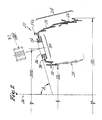
- Figure 2 shows a section through the liner together with other parts of an entire combustor assembly, in phantom. For clarity, most of the small diameter holes which perforate the segments are not shown in this the cross section or in the other drawings of this application.
- This entire liner is comprised of a cylindrical outer wall 24 running around the central axis 26 and a cylindrical inner wall portion 28 shown in phantom. Both are made of welded together circular segments 22.
- the inner wall portion 28 mechanically mates with a tongue or boss 32 of the bulkhead 30.
- Circumferentially spaced apart around the bulkhead is a multiplicity of support rings 34, welded in place.
- each support ring receives a fuel nozzle 37, shown in phantom.
- the fuel nozzle nor the inner liner are present during the processing which is described hereinafter. It will be apparent that the bulkhead could be fixed to the inner wall instead of the outer in another liner, for which the method will be equally useful in repairing.
- the combustor liner has a number of dimensional check points. Included in these are the outside diameter OD, the inside diameter ID, the axial relationship between the boss 32 and the mounting lug 34a, and so forth. Most particularly, the present method is concerned with the proper locating of the diameter SRD of the support rings 34. The method is also concerned with obtaining the desired angular alignment A of the surface 36 of each support ring 34 with respect to the axis 26. Typically, the support ring location diameter SRD in a used combustor liner is less than both that which it had when it was new and that which is required in a remanufactured product.
- the old support rings are cut away at their periphery joint 38 where they are welded and new support rings are inserted.
- the support rings are fixtured with respect to the parts 30, 24 of the liner. After GTAW welding, the weldment is removed from the fixture. We have discovered that despite the accuracy of the fixture, the diameter SRD will be typically found to be less than that which is sought. This has necessitated reforming.
- the principles of the method are illustrated by Figures 1, 3 and 4.
- the liner portion 20 is carefully heated in certain localized areas to about 980°C and while in that condition, the plurality of support rings are moved radially outward to a certain position.
- the combustor liner section is mounted on a fixture (shown in fragment in Figure 4) which is comprised of a multiplicity of segments 42 adapted to move radially outward in directions 44 when a central tapered cone 46 moves downward due to the action of a hydraulic cylinder 48.
- the outward travel of the segments is controlled by an adjustable stop nut 50 mounted on the cone 46. This hits the upper surface 52 of the segments.
- each support ring is clamped to a segment 42 by means of a bolt 54 and a disk 56.
- the disk 56 is flanged to insure that the ring 34 is held firmly against the surface 58 of the fixture which has a slope which yields the desired orientation angle A of the supports.
- each segment has a step 60 or other contour at its outer periphery to receive the steps in the segments of the outer wall 24 of the combustor liner part being repaired.
- Induction heating coils 62, 64 are circularly mounted in close proximity to two portions of the combustor liner. This is shown in both Figures 1 and 3. It is seen that the inner coil 62 and outer coil 64 are connected in series and are part of the same continuous loop connected to a single induction heating machine. Of course, separate loops connected in parallel (with appropriate balancing) or loops connected to separate machines may be used as well. Each turn has fibrous insulation 66,66', such as alumina silicate fiber wrapped around its circumference, to prevent electrical contact with the liner and at the same time to permit the closest possible spacing. When the combustor liner is securely bolted in the fixture segments, the induction heating coils 62, 64 are loosely taped to the liner in the positions shown.
- the band regions 88, 90 adjacent the coils are heated using an induction heating machine such as a TOCCO (Cleveland, Ohio) Model 2CS1-1 Induction Heating Machine with a frequency of 10,000 Herzt, running at about 200 volts, 120 amperes and 20 kilowatts.
- the liner is heated first to a temperature of 870°C, where it is held for 2 minutes; it is then raised to 925°C and held for 30 seconds whereafter it is raised to 980°C and held for approximately 15-20 seconds.
- the temperatures are monitored by thermocouples attached at selected locations to the liner. The reason for preferring the stepping in the heating cycle is to insure that there is an evenness of heat. Other cycles may be used.
- These heated regions comprise a relatively narrow band 88 at the intersection of the outer cylindrical section 24 and the flange portion 30, and another relatively narrow circumferential band 90 on the opposite side of the support ring circle.
- the region 90 is on the portion of the bulkhead which extends transversely farthest from the circular portion 24.
- Each disk 56 has a hole 57 which is elongated in the direction transverse to the plane of the Figure 3 cross section.
- Each disk is bolted to the surface 58 with sufficient force to keep it from lifting, but with insufficient force to keep it from sliding laterally, or circumferentially, as allowed by the slot orientation. This practice enables the support rings to maintain their even spacing during reshaping, when less fixture segments are used than there are support rings, as are preferred. Without the slotting of the disks, the part being reformed is prone to buckling.
- Means for localized heating the areas we describe may be used beyond induction heating. For instance, laser or radiant heating may be used. Additionally, different temperatures may be used as experience dictates, according to the observed behavior and according to other metals which may be used in combustor liners.
- Hastelloy X up to 980°C
- the lower end of the hot working range of 980 ⁇ 1200°C where the yield strength is decreased to about 103 MPa, which is about 25% of the yield strength typical of room temperature.
- higher temperatures in the hot working range may be used according to the characteristics of the material, the fixture force available, and the observed results, etc.
Landscapes
- Engineering & Computer Science (AREA)
- Mechanical Engineering (AREA)
- Chemical & Material Sciences (AREA)
- Combustion & Propulsion (AREA)
- General Engineering & Computer Science (AREA)
- Pressure Welding/Diffusion-Bonding (AREA)
- Heat Treatment Of Articles (AREA)
- Turbine Rotor Nozzle Sealing (AREA)
- General Induction Heating (AREA)
- Stored Programmes (AREA)
Applications Claiming Priority (2)
| Application Number | Priority Date | Filing Date | Title |
|---|---|---|---|
| US480658 | 1983-03-31 | ||
| US06/480,658 US4498617A (en) | 1983-03-31 | 1983-03-31 | Method for reshaping a gas turbine engine combustor part |
Publications (3)
| Publication Number | Publication Date |
|---|---|
| EP0138887A1 EP0138887A1 (en) | 1985-05-02 |
| EP0138887A4 EP0138887A4 (en) | 1985-07-30 |
| EP0138887B1 true EP0138887B1 (en) | 1988-01-13 |
Family
ID=23908836
Family Applications (1)
| Application Number | Title | Priority Date | Filing Date |
|---|---|---|---|
| EP84901166A Expired EP0138887B1 (en) | 1983-03-31 | 1984-02-23 | Method for reshaping a gas turbine engine combustor part |
Country Status (11)
| Country | Link |
|---|---|
| US (1) | US4498617A (enExample) |
| EP (1) | EP0138887B1 (enExample) |
| JP (1) | JPS60500756A (enExample) |
| KR (1) | KR920004878B1 (enExample) |
| AU (1) | AU559368B2 (enExample) |
| CA (1) | CA1232433A (enExample) |
| DE (1) | DE3468635D1 (enExample) |
| ES (1) | ES531154A0 (enExample) |
| IN (1) | IN159485B (enExample) |
| WO (1) | WO1984003851A1 (enExample) |
| ZA (1) | ZA841571B (enExample) |
Families Citing this family (14)
| Publication number | Priority date | Publication date | Assignee | Title |
|---|---|---|---|---|
| US4611744A (en) * | 1982-06-23 | 1986-09-16 | Refurbished Turbine Components Ltd. | Turbine blade repair |
| US5554837A (en) * | 1993-09-03 | 1996-09-10 | Chromalloy Gas Turbine Corporation | Interactive laser welding at elevated temperatures of superalloy articles |
| JP2877296B2 (ja) * | 1995-09-11 | 1999-03-31 | 三菱重工業株式会社 | ガスタービン燃焼器の取付、取外し装置 |
| US5921075A (en) * | 1995-10-19 | 1999-07-13 | Mitsubishi Jukogyo Kabushiki Kaisha | Burner replacing system |
| AT407498B (de) * | 1997-04-07 | 2001-03-26 | Schuoecker Dieter Dr | Verfahren zur materialbearbeitung durch kombination von mechanischer krafteinwirkung und laserstrahlung |
| US6629415B2 (en) | 2001-10-27 | 2003-10-07 | General Electric Co. | Methods and apparatus for modeling gas turbine engine combustor liners |
| US6910859B2 (en) | 2003-03-12 | 2005-06-28 | Pcc Structurals, Inc. | Double-walled annular articles and apparatus and method for sizing the same |
| US7503113B2 (en) * | 2005-10-13 | 2009-03-17 | Siemens Energy, Inc. | Turbine vane airfoil reconfiguration system |
| EP2070709B1 (en) | 2007-12-14 | 2011-11-23 | Seiko Epson Corporation | An exposure head, a method of controlling an exposure head and an image forming apparatus |
| US8245399B2 (en) * | 2009-01-20 | 2012-08-21 | United Technologies Corporation | Replacement of part of engine case with dissimilar material |
| US20120137695A1 (en) * | 2010-12-01 | 2012-06-07 | General Electric Company | Fuel nozzle with gas only insert |
| KR102088688B1 (ko) * | 2018-09-14 | 2020-03-13 | 한국전력공사 | 저주파 유도 가열을 이용한 로터 벤딩 교정 방법 및 이를 이용한 로터 벤딩 교정 장치 |
| CN109365947B (zh) * | 2018-12-06 | 2021-02-23 | 中国航发贵州黎阳航空动力有限公司 | 火焰筒头部组件的真空钎焊夹具及方法 |
| CN110732766B (zh) * | 2019-11-18 | 2021-04-23 | 中国航发贵州黎阳航空动力有限公司 | 航空发动机火焰筒真空电子束焊接变形控制方法及装置 |
Family Cites Families (10)
| Publication number | Priority date | Publication date | Assignee | Title |
|---|---|---|---|---|
| US1153480A (en) * | 1915-03-26 | 1915-09-14 | E & B Holmes Machinery Company | Hoop expanding and flaring machine. |
| DE363145C (de) * | 1921-12-21 | 1922-11-04 | Mannesmann Ag | Vorrichtung zum Richten und Zentrieren von eisernen Reifen fuer Hohlkoerper |
| US1926400A (en) * | 1932-02-03 | 1933-09-12 | Kelsey Hayes Wheel Corp | Apparatus for forming rim members |
| US2340950A (en) * | 1940-03-09 | 1944-02-08 | William H Ferguson | Shrinking dolly block |
| FR1062227A (fr) * | 1951-09-12 | 1954-04-21 | Timken Roller Bearing Co | Procédé de travail à froid de bagues en acier austénitique |
| US3205691A (en) * | 1959-12-15 | 1965-09-14 | Republic Aviat Corp | Method of and apparatus for fabricating hollow articles |
| US3832509A (en) * | 1973-05-29 | 1974-08-27 | V Mikhailov | Split-type magnetic field concentrator |
| US3852990A (en) * | 1973-08-06 | 1974-12-10 | Lockheed Aircraft Corp | Process for removing surface distortion from a metal article |
| US4365470A (en) * | 1980-04-02 | 1982-12-28 | United Technologies Corporation | Fuel nozzle guide and seal for a gas turbine engine |
| US4408382A (en) * | 1981-12-21 | 1983-10-11 | Westinghouse Electric Corp. | Method for removing and replacing shrunk-on sleeves on a shaft |
-
1983
- 1983-03-31 US US06/480,658 patent/US4498617A/en not_active Expired - Lifetime
-
1984
- 1984-02-23 JP JP59501168A patent/JPS60500756A/ja active Granted
- 1984-02-23 WO PCT/US1984/000263 patent/WO1984003851A1/en not_active Ceased
- 1984-02-23 DE DE8484901166T patent/DE3468635D1/de not_active Expired
- 1984-02-23 EP EP84901166A patent/EP0138887B1/en not_active Expired
- 1984-02-23 AU AU26577/84A patent/AU559368B2/en not_active Ceased
- 1984-03-01 ZA ZA841571A patent/ZA841571B/xx unknown
- 1984-03-21 CA CA000450114A patent/CA1232433A/en not_active Expired
- 1984-03-23 IN IN198/CAL/84A patent/IN159485B/en unknown
- 1984-03-30 ES ES531154A patent/ES531154A0/es active Granted
- 1984-03-31 KR KR1019840001702A patent/KR920004878B1/ko not_active Expired
Also Published As
| Publication number | Publication date |
|---|---|
| CA1232433A (en) | 1988-02-09 |
| US4498617A (en) | 1985-02-12 |
| AU559368B2 (en) | 1987-03-05 |
| EP0138887A1 (en) | 1985-05-02 |
| WO1984003851A1 (en) | 1984-10-11 |
| IN159485B (enExample) | 1987-05-23 |
| JPH0429448B2 (enExample) | 1992-05-19 |
| DE3468635D1 (en) | 1988-02-18 |
| JPS60500756A (ja) | 1985-05-23 |
| EP0138887A4 (en) | 1985-07-30 |
| AU2657784A (en) | 1984-10-25 |
| KR840008032A (ko) | 1984-12-12 |
| ES8506158A1 (es) | 1985-06-16 |
| KR920004878B1 (ko) | 1992-06-19 |
| ZA841571B (en) | 1984-10-31 |
| ES531154A0 (es) | 1985-06-16 |
Similar Documents
| Publication | Publication Date | Title |
|---|---|---|
| EP0138887B1 (en) | Method for reshaping a gas turbine engine combustor part | |
| EP1174209B1 (en) | Method of repairing combustion chamber liners | |
| US4924581A (en) | Turbine air seal repair process | |
| US6247231B1 (en) | Method for repairing heat exchanger tubing through partial tube replacement | |
| CA1263221A (en) | Process for the repair by lining of a steam-generator tube and a repair lining for this tube | |
| EP1266718B1 (en) | Methods for replacing nuggeted combustor liner panels | |
| CN115156359A (zh) | 用于航空发动机钣金筒体径向孔局部加热成型装置 | |
| US3594894A (en) | Method of forming cartridges | |
| US6931728B2 (en) | Test model for a gas turbine combustor dome and method of fabricating | |
| US20140318150A1 (en) | Removable swirler assembly for a combustion liner | |
| US6844520B2 (en) | Methods for fabricating gas turbine engine combustors | |
| JP5149611B2 (ja) | 燃焼器ライナ交換用パネル | |
| EP2208865B1 (en) | Method for repairing distorted gas turbine engine components | |
| CA2935760A1 (en) | Gas turbine engine combustor and method of forming same | |
| JP2008157248A (ja) | 燃焼器ライナを修理する方法 | |
| JP5149612B2 (ja) | 燃焼器ライナ交換用パネルを製造する方法 | |
| CN221695583U (zh) | 一种用于多叶片电子束焊接的防飞溅、防变形工装 | |
| US12078355B2 (en) | Resonator ring, method and basket | |
| CN220769559U (zh) | 排气段承力机匣 | |
| WO2024030602A1 (en) | Cooled flare tip barrel | |
| US20030230119A1 (en) | Unitary wrought spinner | |
| JP2011202649A (ja) | ガスタービン部材の変形修正方法 | |
| WO1995029487A1 (en) | Reactor core shroud repair with welded brackets | |
| JPS5954466A (ja) | 殻状主部材に他部材を接合する方法 | |
| JP2001324588A (ja) | 原子炉圧力容器の容器胴の製造方法 |
Legal Events
| Date | Code | Title | Description |
|---|---|---|---|
| PUAI | Public reference made under article 153(3) epc to a published international application that has entered the european phase |
Free format text: ORIGINAL CODE: 0009012 |
|
| AK | Designated contracting states |
Designated state(s): DE GB SE |
|
| 17P | Request for examination filed |
Effective date: 19850308 |
|
| 17Q | First examination report despatched |
Effective date: 19860717 |
|
| GRAA | (expected) grant |
Free format text: ORIGINAL CODE: 0009210 |
|
| AK | Designated contracting states |
Kind code of ref document: B1 Designated state(s): DE GB SE |
|
| REF | Corresponds to: |
Ref document number: 3468635 Country of ref document: DE Date of ref document: 19880218 |
|
| PLBE | No opposition filed within time limit |
Free format text: ORIGINAL CODE: 0009261 |
|
| STAA | Information on the status of an ep patent application or granted ep patent |
Free format text: STATUS: NO OPPOSITION FILED WITHIN TIME LIMIT |
|
| 26N | No opposition filed | ||
| PGFP | Annual fee paid to national office [announced via postgrant information from national office to epo] |
Ref country code: SE Payment date: 19920120 Year of fee payment: 9 |
|
| PG25 | Lapsed in a contracting state [announced via postgrant information from national office to epo] |
Ref country code: SE Effective date: 19930224 |
|
| EUG | Se: european patent has lapsed |
Ref document number: 84901166.3 Effective date: 19930912 |
|
| REG | Reference to a national code |
Ref country code: GB Ref legal event code: IF02 |
|
| PGFP | Annual fee paid to national office [announced via postgrant information from national office to epo] |
Ref country code: GB Payment date: 20030207 Year of fee payment: 20 |
|
| PGFP | Annual fee paid to national office [announced via postgrant information from national office to epo] |
Ref country code: DE Payment date: 20030415 Year of fee payment: 20 |
|
| PG25 | Lapsed in a contracting state [announced via postgrant information from national office to epo] |
Ref country code: GB Free format text: LAPSE BECAUSE OF EXPIRATION OF PROTECTION Effective date: 20040222 |
|
| REG | Reference to a national code |
Ref country code: GB Ref legal event code: PE20 |