EP0138818B1 - Combined elevating platform and mounting device for a tailgate elevator and platform and support member for such a combination - Google Patents
Combined elevating platform and mounting device for a tailgate elevator and platform and support member for such a combination Download PDFInfo
- Publication number
- EP0138818B1 EP0138818B1 EP83903430A EP83903430A EP0138818B1 EP 0138818 B1 EP0138818 B1 EP 0138818B1 EP 83903430 A EP83903430 A EP 83903430A EP 83903430 A EP83903430 A EP 83903430A EP 0138818 B1 EP0138818 B1 EP 0138818B1
- Authority
- EP
- European Patent Office
- Prior art keywords
- platform
- support member
- elevating platform
- elevating
- mounting device
- Prior art date
- Legal status (The legal status is an assumption and is not a legal conclusion. Google has not performed a legal analysis and makes no representation as to the accuracy of the status listed.)
- Expired
Links
- 230000003028 elevating effect Effects 0.000 title claims abstract description 74
- 238000001125 extrusion Methods 0.000 claims description 3
- 238000003801 milling Methods 0.000 abstract description 3
- 238000003466 welding Methods 0.000 description 2
- 230000008901 benefit Effects 0.000 description 1
- 230000008878 coupling Effects 0.000 description 1
- 238000010168 coupling process Methods 0.000 description 1
- 238000005859 coupling reaction Methods 0.000 description 1
- 238000005520 cutting process Methods 0.000 description 1
- 230000007246 mechanism Effects 0.000 description 1
- 238000000034 method Methods 0.000 description 1
- 230000008569 process Effects 0.000 description 1
- 230000009467 reduction Effects 0.000 description 1
Images
Classifications
-
- B—PERFORMING OPERATIONS; TRANSPORTING
- B60—VEHICLES IN GENERAL
- B60P—VEHICLES ADAPTED FOR LOAD TRANSPORTATION OR TO TRANSPORT, TO CARRY, OR TO COMPRISE SPECIAL LOADS OR OBJECTS
- B60P1/00—Vehicles predominantly for transporting loads and modified to facilitate loading, consolidating the load, or unloading
- B60P1/44—Vehicles predominantly for transporting loads and modified to facilitate loading, consolidating the load, or unloading having a loading platform thereon raising the load to the level of the load-transporting element
- B60P1/4414—Vehicles predominantly for transporting loads and modified to facilitate loading, consolidating the load, or unloading having a loading platform thereon raising the load to the level of the load-transporting element and keeping the loading platform parallel to the ground when raising the load
-
- Y—GENERAL TAGGING OF NEW TECHNOLOGICAL DEVELOPMENTS; GENERAL TAGGING OF CROSS-SECTIONAL TECHNOLOGIES SPANNING OVER SEVERAL SECTIONS OF THE IPC; TECHNICAL SUBJECTS COVERED BY FORMER USPC CROSS-REFERENCE ART COLLECTIONS [XRACs] AND DIGESTS
- Y10—TECHNICAL SUBJECTS COVERED BY FORMER USPC
- Y10S—TECHNICAL SUBJECTS COVERED BY FORMER USPC CROSS-REFERENCE ART COLLECTIONS [XRACs] AND DIGESTS
- Y10S414/00—Material or article handling
- Y10S414/13—Handlers utilizing parallel links
Definitions
- the present invention relates to a combined elevating platform and mounting device for attaching the platform to a tailgate elevator of an automotive truck, said tailgate elevator being of the parallellogram type and including a lifting cylinder linked to a lifting arm and a supporting arm, said lifting arm and said supporting arm at one end engaging a support member of the mounting device connected to the elevating platform via horizontal mutually spaced pivot shafts for pivoting the elevating platform by means of the lifting cylinder.
- elevating platforms together with their associated support members, are known to the art.
- the design of the support member depends, to a large extent, on the kind of tailgate elevator for which it is intended, and to the rocker or pivot arrangement used in each individual case.
- the support member In many cases it is difficult to provide a simple and reliable mounting device for connecting the support member to the tailgate elevator and the elevating platform.
- the support member must be capable of taking up the high loads and stresses to which the platform is subjected, and to transfer these loads and stresses to the tailgate elevator while, at the same time, enabling the elevating platform to be swung readily in the vertical plane.
- it must also be possible to raise the platform readily to a vertical position, even when the platform is located in its lower position. Otherwise, when occupying its lower position the platform may prevent the truck from being reversed closely into a loading bridge. It is sometimes necessary to bring the truck as close as possible to the loading bridge, especially when loading is to be carried out under cover with respect to weather conditions.
- US-A-2,348,993 (Novotney) describes a combination of the kind stated in the preamble of claim 1 and including an elevating gate whose support members take the shape of brackets secured to a transverse tie rod.
- the gate which is lifted to its upper position by means of a hoist rests on the bracket members and is pivotable relative thereto about a further shaft engaged by outer support arms which have a bend at their outer ends.
- the combined elevating platform and mounting device is of the kind defined in the preamble of claim 1 and is characterized in that said platform comprises extruded sections and tapers from said forward thick end towards a rear end and in that in the region of the forward thick end there is an elongate bore or hole formed during the extrusion process through all or a substantial part of the section, said bore or hole extending at right angles to the forward/rear direction of said platform and being adapted to receive one or more pivot shafts connecting said platform to one or more said support members received in one or more recesses in teh platform.
- the invention provides a simplified attachment arrangement in which the various components are connected together in the stated simple fashion.
- An additional advantage is that the elevating platform can be delivered together with its associated support member or members, whereupon the platform can be mounted onto the automotive truck for which it is intended, subsequent to effecting a simple milling or cutting operation. When mounting the support member welding operations which normally are both complicated and expensive may be avoided.
- elevating platform can also be arranged to co-act with support members of differing size, hole diameters etc. in dependence upon prevailing circumstances. This greatly simplifies the problem of stocking and handling such platforms.
- the support member engages the platform along a substantial part of the height of the recess, and preferably along the whole height thereof. In this way, the loads and stresses dealt with by the support member are distributed over a relatively wide area, which enhances the reliability of the arrangement.
- the elevating platform is pivotable relative to the support member, and can be swung to a vertical position through the application of an external force, for example a manual force.
- the support member remains in position when the elevating platform is swung upwardly, which can thus be effected in an extremely ready manner, even when the elevating platform occupies its lower position, for example, in order to enable the truck to be reversed to a position in which the said truck is located close to the loading bridge.
- the support arm may comprise a rocker cylinder which is kept of uniform length when the platform is pivoted between its lower and its upper position, said rocker cylinder, however, being expanded and retracted, respectively, for swinging said platform from a horizontal to a vertical and back to a horizontal position.
- This design is characterized in that the support member by means of a screw, bolt or similar releasable means is secured to the platform.
- the support member may alternatively be provided with a depending lug, pivotably connected to a rocker cylinder device, the piston rod of which engages the elevating platform for swinging said platform in the vertical plane.
- a rocker cylinder device can, instead, be arranged to engage a pivot shaft associated with the support member at a lower level and to one side of the point of engagement of the elevating platform.
- the rocker cylinder device is then maintained at a constant length and serves as the support arm during pivoting of the elevating platform between said upper and said lower position.
- the rocker cylinder is, however, extended and retracted, respectively, for swinging the platform from horizontal to vertical position and vice versa.
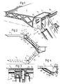
- Figure 1 is a partially cut-away view in perspective of the tailgate elevator of an automotive truck, with associated support member and elevating platform according to the present invention.
- An automotive truck (not shown) carries at its rear end an elevating platform 1 by means of a tailgate elevator 2 of the parallellogram type.
- a tailgate elevator 2 of the parallellogram type.
- the elevating platform is arranged to co-act with two such tailgate elevators arranged in duplicate, only one tailgate elevator is shown, for the sake of simplicity.
- the tailgate elevator includes a lifting cylinder 3, which is connected to a lifting arm 4, which engages the elevating platform 1 via a support member 7, which will be described in more detail hereinafter.
- the tailgate elevator is also arranged to co-act with a lifting arm, which has the form of a rocker cylinder device with associated piston rod 5a.
- the piston rod 5a engages the support member 7 via a pivot pin 7a.
- the elevating platform 1 has a planar undersurface and tapers from its forward, thick end, in the region of which the support member is located.
- the elevating platform comprises two or more extruded sections, which are welded together. Alternatively, the various sections may be pivotably connected together, in order to enable the elevating platform to be collapsed in concertina fashion.
- Milled in the thick end of the elevating platform 1 is a recess la for accommodating the support member 7.
- the length of the recess 1a a corresponds to the length of the support member 7, and in the position illustrated in Figure 1 the height of the support member corresponds to the height of the recess la, i.e. so that the support member engages the recess in the elevating platform via a surface of substantial size.
- the support member 7 is connected to the elevating platform 1 via a pivot shaft 6, which also serves as the horizontal pivot shaft of the elevating platform.
- the lifting arm 4 is pivotally connected to the aforesaid pivot shaft or bolt 6.
- attachment of the support member has been achieved by milling the recess 1a in the thick end of the elevating platform, and then introducing the support member 7 into the said recess and connecting the said member to the elevating platform 1 and the lifting arm 4 by means of bolts 6, said bolts passing through holes bored in the sides of the support member and aligned with an elongate hole la passing through the platform.
- the bolts 6 are held in place by transverse pins (not shown).
- FIG 2 illustrates in principle, pivoting of the elevating platform 1 between its upper and its lower position, the figure also illustrating how the elevating platform can be swung vertically in the upper position by means of the rocker cylinder 5.
- the support member 7 and the elevating platform 1 are joined together by means of a screw 10. In this case, the support member will therefore accompany the elevating platform when it is swung to its vertical position.
- the sole connection between the support member 7 and the elevating platform 1 may comprise the shaft 6, in which case the elevating platform - even when occupying its lower position - can thus be swung relative to the support member 7, by means of an external force, for example a manual force.
- an external force for example a manual force.
- the elevating platform can be pivoted upwardly by means of an external force - even when the platform occupies its upper position - the rocker cylinder 5 and the piston rod 5a can be replaced with a support link (not shown).
- FIG 4 illustrates an alternative arrangement in which the elevating platform 1 can be pivoted relative to the support member 7, and thus where there is no fixed connection between elevating platform and support member.
- the support member 7 is provided with a downwardly extending lug 7b, in which there is accommodated a pivot shaft 7c which is connected to a rocker cylinder device 5.
- the piston rod 5a of the rocker cylinder device engages the underside of the elevating platform 1.
- a simple support arm 5' is used in the Figure 4 embodiment.
- any suitable form of connecting means may be used.
- the support member and/or the elevating platform may be provided with a hook-shaped member arranged to engage a corresponding member on the other part.
- other kinds of readily disconnectable coupling means can be used.
- the elevating platform 1 may comprise one or more extruded sections. In the region of the forward edge of one such section there is an elongate bore or hole Ib extending in parallel with said forward edge.
- the platforms may be delivered along with support members of different size. Later on it is determined which support member shall be used for a certain application.
- Corresponding recesses 1 a are milled and the combined platform and mounting device are put together in the described simple manner avoiding welding operations. A substantial reduction of costs both for producing and storing platforms and support members and for mounting the parts together has then been achieved.
Landscapes
- Engineering & Computer Science (AREA)
- Transportation (AREA)
- Mechanical Engineering (AREA)
- Forklifts And Lifting Vehicles (AREA)
- Jib Cranes (AREA)
- Types And Forms Of Lifts (AREA)
- Load-Engaging Elements For Cranes (AREA)
Priority Applications (1)
| Application Number | Priority Date | Filing Date | Title |
|---|---|---|---|
| AT83903430T ATE24297T1 (de) | 1982-10-25 | 1983-10-25 | Ladebuehne und aufhaengevorrichtung fuer eine kombinierte hebe- und ladebuehne und stuetzteil fuer eine solche zusammenstellung. |
Applications Claiming Priority (2)
| Application Number | Priority Date | Filing Date | Title |
|---|---|---|---|
| SE8206048A SE434934B (sv) | 1982-10-25 | 1982-10-25 | Anordning for infestning av lyftbrygga till ett lastfordons bakgavellyft |
| SE8206048 | 1982-10-25 |
Publications (2)
| Publication Number | Publication Date |
|---|---|
| EP0138818A1 EP0138818A1 (en) | 1985-05-02 |
| EP0138818B1 true EP0138818B1 (en) | 1986-12-17 |
Family
ID=20348339
Family Applications (1)
| Application Number | Title | Priority Date | Filing Date |
|---|---|---|---|
| EP83903430A Expired EP0138818B1 (en) | 1982-10-25 | 1983-10-25 | Combined elevating platform and mounting device for a tailgate elevator and platform and support member for such a combination |
Country Status (6)
| Country | Link |
|---|---|
| US (1) | US4569626A (da) |
| EP (1) | EP0138818B1 (da) |
| DE (1) | DE3368399D1 (da) |
| DK (1) | DK153748C (da) |
| SE (1) | SE434934B (da) |
| WO (1) | WO1984001751A1 (da) |
Families Citing this family (14)
| Publication number | Priority date | Publication date | Assignee | Title |
|---|---|---|---|---|
| NL8402442A (nl) * | 1984-08-07 | 1986-03-03 | Asselt Christiaan Van | Laad- en losklep in het bijzonder voor een vrachtwagen met een laadvloer. |
| US4822237A (en) * | 1985-11-21 | 1989-04-18 | The Gradall Company | Extended reach materials handling apparatus |
| US4729712A (en) * | 1986-08-15 | 1988-03-08 | Corley Jr Quentin D | Vehicle lift gate with upright storage |
| BE1000012A6 (nl) * | 1987-02-03 | 1987-11-10 | Elskamp Hendrika Johanna Echtg | Inrichting voor het sturen van een laadplatform voor transportvoertuigen. |
| JPH01301423A (ja) * | 1988-05-30 | 1989-12-05 | Shinmeiwa Auto Eng Kk | 荷受台昇降装置 |
| US5588793A (en) * | 1995-03-02 | 1996-12-31 | Chang; Hueng-San | Elevator mechanism for vehicle |
| DE19632725C2 (de) * | 1996-08-03 | 2000-09-14 | Alusuisse Lonza Services Ag | Plattform, insbesondere Ladebordwand für Fahrzeuge |
| ATE196623T1 (de) * | 1996-08-03 | 2000-10-15 | Maier Gmbh Peter | Plattform, insbesondere ladebordwand für fahrzeuge |
| GB2376221B (en) * | 2001-06-05 | 2004-08-11 | Del Equipment | A vehicle mounted elevator assembly |
| US6719349B2 (en) * | 2002-03-08 | 2004-04-13 | Caterpillar S.A.R.L. | Tailgate assembly |
| US20040191039A1 (en) * | 2002-12-12 | 2004-09-30 | Lundeen Paul H. | Device for loading material into hauling vehicles |
| US6685421B1 (en) | 2003-01-02 | 2004-02-03 | Charles N. Reeves | Hitch-mounted lift assembly |
| DE102010052816A1 (de) | 2010-11-29 | 2012-05-31 | Biso Schrattenecker Gmbh | Erntevorsatz für eine Erntemaschine |
| US8668427B1 (en) | 2011-09-26 | 2014-03-11 | Ronald G. England | Bridge for a tailgate of a pickup truck |
Family Cites Families (3)
| Publication number | Priority date | Publication date | Assignee | Title |
|---|---|---|---|---|
| US2348993A (en) * | 1943-05-07 | 1944-05-16 | Frank A Novotney | Elevating gate |
| US2525424A (en) * | 1947-06-20 | 1950-10-10 | Anthony Co | Balancing means for tail gate elevators |
| EP0081115B1 (de) * | 1981-12-09 | 1986-02-19 | Austria Metall Aktiengesellschaft | Anschlussprofil für eine Lade-Plattform, insbesondere für Fahrzeuge |
-
1982
- 1982-10-25 SE SE8206048A patent/SE434934B/sv not_active IP Right Cessation
-
1983
- 1983-10-25 WO PCT/SE1983/000362 patent/WO1984001751A1/en not_active Ceased
- 1983-10-25 EP EP83903430A patent/EP0138818B1/en not_active Expired
- 1983-10-25 DE DE8383903430T patent/DE3368399D1/de not_active Expired
- 1983-10-25 US US06/624,502 patent/US4569626A/en not_active Expired - Fee Related
-
1984
- 1984-06-21 DK DK302784A patent/DK153748C/da not_active IP Right Cessation
Also Published As
| Publication number | Publication date |
|---|---|
| DE3368399D1 (en) | 1987-01-29 |
| EP0138818A1 (en) | 1985-05-02 |
| DK302784D0 (da) | 1984-06-21 |
| SE8206048L (sv) | 1984-04-26 |
| SE8206048D0 (sv) | 1982-10-25 |
| DK302784A (da) | 1984-06-21 |
| DK153748B (da) | 1988-08-29 |
| SE434934B (sv) | 1984-08-27 |
| DK153748C (da) | 1989-01-23 |
| US4569626A (en) | 1986-02-11 |
| WO1984001751A1 (en) | 1984-05-10 |
Similar Documents
| Publication | Publication Date | Title |
|---|---|---|
| EP0138818B1 (en) | Combined elevating platform and mounting device for a tailgate elevator and platform and support member for such a combination | |
| US8807907B2 (en) | Apparatus for level ride lift | |
| US4948326A (en) | Load lifting attachment mounted on a truck frame | |
| US6082958A (en) | Lift-type loading platform system | |
| EP0372246A1 (en) | Platform elevating apparatus | |
| US5067862A (en) | Unitary carrying assembly or unit for motor-car trailer vehicles | |
| US4053074A (en) | Device for handling a vehicle-carried container | |
| US4729712A (en) | Vehicle lift gate with upright storage | |
| US4953666A (en) | Elevating apparatus having an offset upper boom maintaining a workstation level on a cantilevered angularly movable support that retracts into a compact position | |
| US4164297A (en) | Folding gooseneck for trailer | |
| US4265587A (en) | Quick-coupling locking mechanism | |
| CA2288236C (en) | Mechanism to fold and unfold truck forks | |
| US5984270A (en) | Jack safety device | |
| US4503935A (en) | Lift jack retention bracket | |
| US4047258A (en) | Lip lock with release and counterbalance for dock board | |
| US5074622A (en) | Scissor frame lift apparatus for dump trucks | |
| EP0148418A2 (en) | Side lifting apparatus | |
| US3429464A (en) | Load lift apparatus with low loading level | |
| US4770271A (en) | Transportable, articulated-arm crane | |
| GB2038284A (en) | Mounting a lifting mast on a vehicle | |
| JPS594600A (ja) | 接近用プラツトフオ−ム | |
| JP4121023B2 (ja) | ステップ一体型荷受台昇降装置 | |
| US4505359A (en) | Vehicle cargo elevator with upright storage | |
| EP0025322A1 (en) | Vehicle for transporting containers | |
| US5219267A (en) | Method for salvaging the contents of a leaking drum |
Legal Events
| Date | Code | Title | Description |
|---|---|---|---|
| PUAI | Public reference made under article 153(3) epc to a published international application that has entered the european phase |
Free format text: ORIGINAL CODE: 0009012 |
|
| 17P | Request for examination filed |
Effective date: 19841106 |
|
| AK | Designated contracting states |
Designated state(s): AT BE CH DE FR GB LI NL SE |
|
| DET | De: translation of patent claims | ||
| GRAA | (expected) grant |
Free format text: ORIGINAL CODE: 0009210 |
|
| AK | Designated contracting states |
Kind code of ref document: B1 Designated state(s): AT BE CH DE FR GB LI NL SE |
|
| REF | Corresponds to: |
Ref document number: 24297 Country of ref document: AT Date of ref document: 19870115 Kind code of ref document: T |
|
| REF | Corresponds to: |
Ref document number: 3368399 Country of ref document: DE Date of ref document: 19870129 |
|
| ET | Fr: translation filed | ||
| PLBI | Opposition filed |
Free format text: ORIGINAL CODE: 0009260 |
|
| 26 | Opposition filed |
Opponent name: ALUMINIUM WALZWERKE SINGEN GMBH Effective date: 19870910 |
|
| NLR1 | Nl: opposition has been filed with the epo |
Opponent name: ALUMINIUM WALZWERKE SINGEN GMBH |
|
| RAP2 | Party data changed (patent owner data changed or rights of a patent transferred) |
Owner name: ALUMINIUM-WALZWERKE SINGEN GMBH Owner name: Z- LYFTEN PRODUKTION AB |
|
| NLT2 | Nl: modifications (of names), taken from the european patent patent bulletin |
Owner name: Z- LYFTEN PRODUKTION AB TE KATRINEHOLM, ZWEDEN EN |
|
| PLBM | Termination of opposition procedure: date of legal effect published |
Free format text: ORIGINAL CODE: 0009276 |
|
| STAA | Information on the status of an ep patent application or granted ep patent |
Free format text: STATUS: OPPOSITION PROCEDURE CLOSED |
|
| 27C | Opposition proceedings terminated |
Effective date: 19881003 |
|
| PGFP | Annual fee paid to national office [announced via postgrant information from national office to epo] |
Ref country code: GB Payment date: 19921021 Year of fee payment: 10 |
|
| PGFP | Annual fee paid to national office [announced via postgrant information from national office to epo] |
Ref country code: AT Payment date: 19921030 Year of fee payment: 10 |
|
| PGFP | Annual fee paid to national office [announced via postgrant information from national office to epo] |
Ref country code: NL Payment date: 19921031 Year of fee payment: 10 |
|
| PGFP | Annual fee paid to national office [announced via postgrant information from national office to epo] |
Ref country code: BE Payment date: 19921106 Year of fee payment: 10 |
|
| PG25 | Lapsed in a contracting state [announced via postgrant information from national office to epo] |
Ref country code: GB Effective date: 19931025 Ref country code: AT Effective date: 19931025 |
|
| PG25 | Lapsed in a contracting state [announced via postgrant information from national office to epo] |
Ref country code: BE Effective date: 19931031 |
|
| BERE | Be: lapsed |
Owner name: Z- LYFTEN PRODUKTION A.B. Effective date: 19931031 Owner name: ALUMINIUM-WALZWERKE SINGEN G.M.B.H. Effective date: 19931031 |
|
| PG25 | Lapsed in a contracting state [announced via postgrant information from national office to epo] |
Ref country code: NL Effective date: 19940501 |
|
| NLV4 | Nl: lapsed or anulled due to non-payment of the annual fee | ||
| GBPC | Gb: european patent ceased through non-payment of renewal fee |
Effective date: 19931025 |
|
| EAL | Se: european patent in force in sweden |
Ref document number: 83903430.3 |
|
| PGFP | Annual fee paid to national office [announced via postgrant information from national office to epo] |
Ref country code: FR Payment date: 19960929 Year of fee payment: 14 |
|
| PGFP | Annual fee paid to national office [announced via postgrant information from national office to epo] |
Ref country code: DE Payment date: 19961001 Year of fee payment: 14 |
|
| PGFP | Annual fee paid to national office [announced via postgrant information from national office to epo] |
Ref country code: CH Payment date: 19961021 Year of fee payment: 14 |
|
| PGFP | Annual fee paid to national office [announced via postgrant information from national office to epo] |
Ref country code: SE Payment date: 19961029 Year of fee payment: 14 |
|
| PG25 | Lapsed in a contracting state [announced via postgrant information from national office to epo] |
Ref country code: SE Free format text: LAPSE BECAUSE OF NON-PAYMENT OF DUE FEES Effective date: 19971026 |
|
| PG25 | Lapsed in a contracting state [announced via postgrant information from national office to epo] |
Ref country code: FR Free format text: THE PATENT HAS BEEN ANNULLED BY A DECISION OF A NATIONAL AUTHORITY Effective date: 19971031 Ref country code: LI Free format text: LAPSE BECAUSE OF NON-PAYMENT OF DUE FEES Effective date: 19971031 Ref country code: CH Free format text: LAPSE BECAUSE OF NON-PAYMENT OF DUE FEES Effective date: 19971031 |
|
| REG | Reference to a national code |
Ref country code: CH Ref legal event code: PL |
|
| PG25 | Lapsed in a contracting state [announced via postgrant information from national office to epo] |
Ref country code: DE Free format text: LAPSE BECAUSE OF NON-PAYMENT OF DUE FEES Effective date: 19980701 |
|
| EUG | Se: european patent has lapsed |
Ref document number: 83903430.3 |
|
| REG | Reference to a national code |
Ref country code: FR Ref legal event code: ST |
|
| PLAB | Opposition data, opponent's data or that of the opponent's representative modified |
Free format text: ORIGINAL CODE: 0009299OPPO |
|
| PG25 | Lapsed in a contracting state [announced via postgrant information from national office to epo] |
Ref country code: FR Free format text: THE PATENT HAS BEEN ANNULLED BY A DECISION OF A NATIONAL AUTHORITY Effective date: 19961031 |