EP0138783A2 - Catalyseur à grands pores pour la conversion d'hydrocarbures lourds - Google Patents
Catalyseur à grands pores pour la conversion d'hydrocarbures lourds Download PDFInfo
- Publication number
- EP0138783A2 EP0138783A2 EP84850244A EP84850244A EP0138783A2 EP 0138783 A2 EP0138783 A2 EP 0138783A2 EP 84850244 A EP84850244 A EP 84850244A EP 84850244 A EP84850244 A EP 84850244A EP 0138783 A2 EP0138783 A2 EP 0138783A2
- Authority
- EP
- European Patent Office
- Prior art keywords
- catalyst
- conversion
- carbon black
- carbon
- range
- Prior art date
- Legal status (The legal status is an assumption and is not a legal conclusion. Google has not performed a legal analysis and makes no representation as to the accuracy of the status listed.)
- Withdrawn
Links
Images


Classifications
-
- B—PERFORMING OPERATIONS; TRANSPORTING
- B01—PHYSICAL OR CHEMICAL PROCESSES OR APPARATUS IN GENERAL
- B01J—CHEMICAL OR PHYSICAL PROCESSES, e.g. CATALYSIS OR COLLOID CHEMISTRY; THEIR RELEVANT APPARATUS
- B01J29/00—Catalysts comprising molecular sieves
- B01J29/04—Catalysts comprising molecular sieves having base-exchange properties, e.g. crystalline zeolites
- B01J29/06—Crystalline aluminosilicate zeolites; Isomorphous compounds thereof
- B01J29/08—Crystalline aluminosilicate zeolites; Isomorphous compounds thereof of the faujasite type, e.g. type X or Y
- B01J29/082—X-type faujasite
-
- B—PERFORMING OPERATIONS; TRANSPORTING
- B01—PHYSICAL OR CHEMICAL PROCESSES OR APPARATUS IN GENERAL
- B01J—CHEMICAL OR PHYSICAL PROCESSES, e.g. CATALYSIS OR COLLOID CHEMISTRY; THEIR RELEVANT APPARATUS
- B01J29/00—Catalysts comprising molecular sieves
- B01J29/04—Catalysts comprising molecular sieves having base-exchange properties, e.g. crystalline zeolites
- B01J29/06—Crystalline aluminosilicate zeolites; Isomorphous compounds thereof
- B01J29/08—Crystalline aluminosilicate zeolites; Isomorphous compounds thereof of the faujasite type, e.g. type X or Y
- B01J29/084—Y-type faujasite
-
- B—PERFORMING OPERATIONS; TRANSPORTING
- B01—PHYSICAL OR CHEMICAL PROCESSES OR APPARATUS IN GENERAL
- B01J—CHEMICAL OR PHYSICAL PROCESSES, e.g. CATALYSIS OR COLLOID CHEMISTRY; THEIR RELEVANT APPARATUS
- B01J37/00—Processes, in general, for preparing catalysts; Processes, in general, for activation of catalysts
- B01J37/0009—Use of binding agents; Moulding; Pressing; Powdering; Granulating; Addition of materials ameliorating the mechanical properties of the product catalyst
- B01J37/0018—Addition of a binding agent or of material, later completely removed among others as result of heat treatment, leaching or washing,(e.g. forming of pores; protective layer, desintegrating by heat)
-
- C—CHEMISTRY; METALLURGY
- C10—PETROLEUM, GAS OR COKE INDUSTRIES; TECHNICAL GASES CONTAINING CARBON MONOXIDE; FUELS; LUBRICANTS; PEAT
- C10G—CRACKING HYDROCARBON OILS; PRODUCTION OF LIQUID HYDROCARBON MIXTURES, e.g. BY DESTRUCTIVE HYDROGENATION, OLIGOMERISATION, POLYMERISATION; RECOVERY OF HYDROCARBON OILS FROM OIL-SHALE, OIL-SAND, OR GASES; REFINING MIXTURES MAINLY CONSISTING OF HYDROCARBONS; REFORMING OF NAPHTHA; MINERAL WAXES
- C10G11/00—Catalytic cracking, in the absence of hydrogen, of hydrocarbon oils
- C10G11/02—Catalytic cracking, in the absence of hydrogen, of hydrocarbon oils characterised by the catalyst used
- C10G11/04—Oxides
- C10G11/05—Crystalline alumino-silicates, e.g. molecular sieves
-
- C—CHEMISTRY; METALLURGY
- C10—PETROLEUM, GAS OR COKE INDUSTRIES; TECHNICAL GASES CONTAINING CARBON MONOXIDE; FUELS; LUBRICANTS; PEAT
- C10G—CRACKING HYDROCARBON OILS; PRODUCTION OF LIQUID HYDROCARBON MIXTURES, e.g. BY DESTRUCTIVE HYDROGENATION, OLIGOMERISATION, POLYMERISATION; RECOVERY OF HYDROCARBON OILS FROM OIL-SHALE, OIL-SAND, OR GASES; REFINING MIXTURES MAINLY CONSISTING OF HYDROCARBONS; REFORMING OF NAPHTHA; MINERAL WAXES
- C10G11/00—Catalytic cracking, in the absence of hydrogen, of hydrocarbon oils
- C10G11/14—Catalytic cracking, in the absence of hydrogen, of hydrocarbon oils with preheated moving solid catalysts
- C10G11/18—Catalytic cracking, in the absence of hydrogen, of hydrocarbon oils with preheated moving solid catalysts according to the "fluidised-bed" technique
-
- B—PERFORMING OPERATIONS; TRANSPORTING
- B01—PHYSICAL OR CHEMICAL PROCESSES OR APPARATUS IN GENERAL
- B01J—CHEMICAL OR PHYSICAL PROCESSES, e.g. CATALYSIS OR COLLOID CHEMISTRY; THEIR RELEVANT APPARATUS
- B01J2229/00—Aspects of molecular sieve catalysts not covered by B01J29/00
- B01J2229/30—After treatment, characterised by the means used
- B01J2229/42—Addition of matrix or binder particles
Definitions
- This invention relates to an improved catalyst, a method for its preparation, and a process for its use in the conversion of petroleum oil feeds containing hydrocarbon molecules of high molecular weight (heavy). More particularly, the invention is related to a catalyst composition comprising a catalytically active crystalline aluminosilicate zeolite uniformly dispersed within a matrix component having large feeder pores for conveying reactants to and reaction products from the zeolitic component.
- gasoline and other liquid hydrocarbon fuels boil in the range of about 38°C to 343°C (100°F to 650°F).
- the crude oils from which these fuels are made contain mixtures of hydrocarbons which boil over wider temperature ranges, the boiling point of each hydrocarbon depending upon its molecular weight.
- the petroleum refining industry has developed a variety of processes for breaking or cracking the large molecules of high molecular weight into smaller molecules which boil within the above boiling range for hydrocarbon fuels.
- the cracking process which is most widely used for this purpose at the present time is known as fluid catalytic cracking (FCC) and may employ a fluidized bed reactor with backmixing and/or a riser reactor with progressive flow.
- FCC fluid catalytic cracking
- feedstock oil is mixed with particulate catalyst at an elevated temperature in the lower portion of an elongated reaction vessel called a "riser".
- a riser in the lower portion of an elongated reaction vessel
- Contact of the hot catalyst with the oil rapidly generates large volumes of gases which propel the stream of feed and catalyst as a suspension through the reaction zone at high velocity, giving relatively short contact time.
- the initial propelling gases are comprised of vaporized oil, the major portion of which boils below 552°C (1025°F) and is immediately vaporized by contact with the hot catalyst which enters the riser at a higher temperature.
- the velocity of the suspension is sometimes increased further by introducing diluent materials into the riser either along with the feed or separately.
- the conversion reaction initiated in the lower portion of the riser continues until the catalyst and gases are separated, which may take place as the suspension leaves the riser reaction zone or in an upper, larger diameter vessel for collecting the catalyst. Upon being separated from the catalyst, the gases are usually referred to as "product vapors".
- Crude oil in its natural state contains a variety of materials which, unless removed prior to the cracking reaction, tend to have troublesome effects on FCC processes. These include coke precursors, such as asphaltenes, polynuclear aromatics and high boiling nitrogen containing molecules; and metals, such as sodium and small amounts of other alkali or alkaline earth metals, nickel, vanadium, iron and copper, which are detrimental to the conversion process and/or to the catalyst.
- coke precursors such as asphaltenes, polynuclear aromatics and high boiling nitrogen containing molecules
- metals such as sodium and small amounts of other alkali or alkaline earth metals, nickel, vanadium, iron and copper, which are detrimental to the conversion process and/or to the catalyst.
- coke precursors either tend to deposit as solid aromatic structures having some residual hydrogen or are high boiling and do not vaporize but lay down on the catalyst as a liquid. These coke deposits block the catalytically active acid sites of the catalyst and thereby reduce its conversion activity. While it is believed that both the solid and liquid components of coke may cover and thereby block acidic sites, the liquid components may also fill pores of the matrix and thereby retard diffusion of lower boiling components to the zeolite.
- the carbonaceous material formed by the conversion process is referred to as coke, it may have hydrogen to carbon ratios of 1.0 or greater and may contain in addition to hydrogen various amounts of other element depending upon the composition of the feed.
- the coke formed is deposited on the catalyst particles and thereby reduces the conversion activity of the catalyst.
- the contaminated catalyst is regenerated by burning off the coke by contacting the catalyst particles at relatively high temperatures with an oxidizing gas such as air.
- the regenerated catalyst may then be returned to the reaction zone for additional passes or conversion cycles in contact with fresh feed.
- the coke-forming tendency or coke precursor content of a feedstock oil can be ascertained by determining the weight percent of residue remaining upon pyrolyzing a sample of the feed.
- Two tests presently recognized by the industry are the Conradson carbon residue test described in ASTM D189-76 and the Ramsbottom carbon test described in ASTM D524-76.
- Conradson carbon residues of about 0.05 to 1.0 are regarded as indicative of relatively contaminate free gas oil feeds.
- the sodium, and other alkali or alkaline earth metals can diffuse to the active, i.e., acidic, sites of the catalyst and poison of kill their catalytic activity. Vanadium, and to a lesser extent nickel and other metals, may also migrate to and poison acidic sites. There metals will therefore be referred to collectively as poison metals.
- Nickel, vanadium, copper and iron are also known as "heavy metals" and catalyze undesirable dehydrogenation reactions which increase the amount of coke deposits on the catalyst and the amounts of hydrogen and normally gaseous hydrocarbons to be handled by process equipment.
- the heavy metals transfer almost quantitively from the feedstock oil to the catalyst particles and tend to deposit on interior and exterior surfaces of the particles wherein they can block and/or retard diffusion to active sites.
- the various heavy metals are not of equal poisoning activity relative to catalytic acid sites, it is convenient to express the poisoning activity of an oil containing one or more of these metals in terms of the amount of a single metal which is estimated to have equivalent poisoning activity.
- crude oils are carefully fractionated to provide a gas oil with a relatively low level of heavy metal contaminants, namely, 0.25 ppm Nickel Equivalents or less.
- the above formula can also be used as a measure of the heavy metals accumulated on the cracking catalyst itself, the quantity of metal used in the formula being based on the weight of moisture-free catalyst.
- equilibrium catalyst is removed and fresh, contaminant-free catalyst is added at a rate sufficiently high to control the heavy metal content of the catalyst at relatively low levels, namely, 1,000 ppm Nickel Equivalents or less.
- Some crude oils contain from about 10% to about 30% by volume of heavy hydrocarbons which will not boil below about 552°C (1025°F) at atmospheric pressure. Atmospheric bottoms and vacuum bottoms may contain even higher percentages of this highest boiling fraction.
- the coke precursor and poison metal components of the crude are for the most part concentrated in this fraction. Accordingly, many of the problems presented by these components have been avoided by sacrificing the yield of liquid fuel fractions which is potentially available from cracking the highest boiling fraction. More particularly, in conventional FCC practice, the crude oil has been vacuum fractionated to provide a FCC feedstock boiling between about 343°C (650°F) and about 538°C (1000°F), this fraction being referred to as a vacuum gas oil and being relatively free of coke precursors and poison metals.
- Vacuum gas oil is generally prepared from crude by distilling off the fraction boiling below about 343°C (650°F) at atmospheric pressure and then separating by vacuum distillation one or more fractions boiling between about 343°C (650°F) and about 552°C (1025°F) from the heaviest fraction boiling about 552°C (1025°F).
- the heaviest fraction is normally not used as a source of catalytic conversion feedstock, but instead is employed for other purposes, such as the production of asphalt, which represents a waste of the potential value of this portion of the crude oil as a source of liquid fuels.
- a catalyst comprised of crystalline zeolite particles embedded within a larger matrix particle has numerous passages leading from the outer peripheral surface of the matrix particle to the smaller zeolite particles supported within the matrix.
- these matrix passages are referred to as "feeder pores”.
- Feeder pores in effect provide access passageways from the surface of each catalyst particle to those zeolite particles at locations internal to the matrix. There also may be a small but finite number of zeolite particles exposed at the surface of the matrix.
- the pores of zeolitic sieves fall within the range of 0 0 4 to 13A. Accordingly, any pores larger than 13A are usually in the matrix.
- the average diameter of feeder pores in fresh catalyst usually falls within the 0 0 range of about 30A to about 400A.
- Alumina-silica matrices generally have pores in this range, although a relatively small proportion may be larger.
- the effective average pore diameter of these prior art catalysts may be decreased significantly because of coke and metal accumulations.
- the low zeolite utilization effect is a consequence primarily of the deposition of both coke and heavy metals in and/or across the mouths of the working pores of the zeolite. These components in effect block off zeolitic pore volume containing unused or incompletely used acidic sites.
- Zeolitic pore volume refers to the free volume of the micro-pores in the zeolite component rather than the matrix.
- pore volume as applied to the catalyst composition as a whole refers to the free volume in the matrix and zeolite combined which is provided by both macropores (pores having a minimum diameter 0 above 30A ) and micropores (pores having a minimum diameter of 0 0 30A or less).
- the pore volume fraction for pores greater than 30A in diameter may be determined by mercury porosimetry methods, such as the method of U.S. Patent No. 3,853,789.
- the pore volume fraction in the 0 to 30A range may be determined by the BET nitrogen adsorption method described by Brunauer, Emmett, and Teller in the Journal of the American Chemical Society, 60, 309 (1938).
- the pore volume of fresh hydrocarbon conversion catalyst may vary widely depending upon the size of the pores in the matrix and, where used, the relative amount of catalytic promoter, such as zeolite, and the size of its pores.
- Diffusion limitations may result from a number of different mechanisms.
- One such limitation is a consequence of high molecular weight molecules in the feed and the absence of a sufficient number of feeder pores of the size range required for transporting these large molecules to the acidic sites of the catalyst, some of which may be in the matrix but the majority of whicn are in the zeolite.
- Another diffusion limitation in the processing of reduced crude or other resid containing feeds is due to what may be called "pore plugging". Pore plugging is caused by the absorption of unvaporized hydrocarbons in the catalyst pores so that they are impractical to remove by stripping operations prior to regeneration. The trapping of heavy hydrocarbons which cannot be removed by conventional stripping operations can lead to excessive coke and regeneration temperatures and increased air consumption.
- Pore plugging and the deposition of coke and/or heavy metals within or over the pores also leads to decreased diffusion of reactants to and products from acidic sites. Slow diffusion rates may result in thermal cracking predominating over catalytic cracking, which in turn causes loss of selectivity.
- catalysts possessing relatively small or restricted feeder pores will show relatively poor cracking characteristics when cracking resid containing feeds, including low conversion, poor selectivity, increased air consumption during regeneration, and higher regeneration temperatures. Hot spots also occur more readily during regeneration and cause catalyst deactivation through sintering of the matrix and loss of zeolite crystalline structure and acidity.
- low catalyst utilization factors and diffusion limitations both require high catalyst to oil ratios which necessitate relatively low oil feed rates.
- Zeolites are crystalline alumino-silicates made up of tetra-coordinated aluminum atoms associated through oxygen atoms with silicon atoms in an ordered crystalline structure. Localized hot spots in or near the zeolite particles can cause destruction of the aluminosilicate crystalline structure, at least to the extent of destroying portal are of the zeolite, with a resulting loss of its catalytic action. Furthermore, both sodium and vanadium contaminates accelerate sintering and collapse of pore structures in both the matrix and zeolite components.
- the present invention provides a catalyst and a process for selective conversion of heavy hydrocarbons. It is therefore a principal object of the invention to provide a special hydrocarbon conversion catalyst resistant to deactivation by severe hydro-thermal conditions and by accumulations of coke precursors and poison metals. Another object of the invention is to provide an improved process for catalytic conversion of high boiling carbo-metallic oil feeds containing relatively high concentrations of coke precursors and poison metals.
- the catalyst and process of the invention are particularly useful for cracking oil feeds which contain significant quantities of residual hydrocarbons, e.g., at least ten percent, boiling above about 552°C (1025°F), and significant quantities of heavy metals, e.g., at least about 4 ppm of Nickel Equivalents.
- Feeder pores having large minimum diameters and large mouths are provided in the catalyst of the invention so as to facilitate diffusion of high molecular weight molecules through the matrix to the portal surface area of the sieve particles.
- the catalyst matrix also has a relatively large pore volume in order to soak up unvaporized portions of the oil feed.
- the feeder pores through the matrix are sufficiently large so that significant number of hydrocarbon molecules can diffuse to active catalytic sites both in the matrix and in the sieve.
- the open channels of these feeder pores are somewhat tortuous and tend to trap molecules having molecular weights of or greater and average 0 diameters of 200A or greater (for example asphaltenes, porphyrins and polynuclear aromatics). These very large molecules can effectively cover and block the relatively small pores of the zeolitic sieve.
- the size and structure of the feeder pores of the invention are such that they remain open without diffusion restrictions even when matrix surfaces and pore channel walls become loaded with very large asphaltene type molecules.
- the optimum average diameter for 0 feeder pores in the catalyst matrix is in the range of 400 to 6000A. It has also been discovered that these pore size ranges can be easily and readily obtained with the use of carbon black particles 0 having a cross-sectional diameter in the range of about 100 to 1000A and a length to diameter ratio greater than about 2:1, preferably greater than about 5:1.
- carbon black particles 0 having a cross-sectional diameter in the range of about 100 to 1000A and a length to diameter ratio greater than about 2:1, preferably greater than about 5:1.
- the fired catalyst has a relatively large and controlled number of feeder pores within the desired size range, the number and size distribution of these pores being enhanced to a significant extent by the type and amount of dispersant used for suspending the carbon black in the aqueous suspension from which the unfired composite is made.
- the large feeder pores of the invention extend from the surface to the interior of the matrix particles and provide access channels to the much smaller zeolite particles supported within the matrix material.
- Carbon black may be incorporated in the catalyst matrix by adding it to a composite catalyst slurry along with the zeolitic component prior to spray drying the slurry to form final microspheres of matrix supported zeolite. Where a kaolin clay composition is spray dried, calcined and then treated to generate zeolite crystals in situ, the carbon black may be added to the clay slurry fed to the spray drier so as to be present in the composition during and after in situ formation of the zeolite within the matrix material.
- a competing consideration for the selectivity desired in cracking residual feeds is that there must be sufficient acid sites present so that catalytic cracking dominates the conversion reaction.
- catalytic surface area may decrease.
- the amount of zeolitic promoter can be increased and/or smaller zeolite particles (crystals) employed to increase the portal surface area of this component.
- a preferred catalyst of the invention therefore contains relatively high concentrations of very small zeolitic sieve particles supported within an alumina, silica and/or alumina-silica matrix. Both the sieve and the matrix should have good steam and thermal stability.
- a "Y" type zeolite sieve relatively free of sodium and stabilized with hydrogen and/or ammonium ions and/or rare earth ions is preferred.
- spray dried microspheres containing carbon black are partially exchanged with rare earths, calcined to remove the carbon black and stabilize the zeolite, and further exchanged with rare earths to provide a catalyst having superior hydrothermal stability.
- Acidic sites may also be provided in the matrix material so that at least some of the heavier hydrocarbons, both liquid and vaporous, can be cracked on the surfaces and in the passages of the matrix to provide a means by which molecules larger than the sieve pores can be converted to smaller molecules of a size small enough to enter and be cracked in the sieve.
- alkyl fragments can be stripped from large aromatic molecules so that the fragments may enter the highly active pores of the zeolite.
- the large feeder pores and process conditions of the present invention provide increased conversion and improved selectivity in the cracking of reduced crude and other resid containing oil feeds.
- these larger pores are capable of maintaining adequate diffusion of reactants and reaction products while providing sufficient pore volume and surface area in the matrix for absorption and retention of poison metals, coke and unvaporizable hydrocarbons.
- a normal C45 hydrocarbon molecule has a boiling point above 815°C (1500°F), a cross-sectional diameter 0 0 of about 4A and a maximum length of about 50A. Therefore, with a conventional catalyst matrix having an effective pore diameter at 0 equilibrium of less than 50A, this heavy molecule can enter the average pore based on its minimum cross-sectional dimension but cannot enter based on its length dimension. Thus some net orientation would be required for heavy molecules of a resid fraction to traverse the pores of the matrix and reach the acid sites of the zeolite.
- heavy molecules such as those having molecular weights in the range of 1000 to 10,000, would exist in a relatively disordered state so that some of the molecules would not be able to enter the matrix of catalysts having relatively small feeder pores. Since the reactants and the products of catalytic conversion must necessarily use the same feeder pore passages and diffuse in opposite directions, the rate of diffusion into a pore must equal the rate of diffusion out under steady state conditions. It is therefore believed that the large feeder pores of the invention decrease the necessity for a particular molecular orientation and therefore increase diffusion rates through these pores, particularly at equilibrium conditions where effective pore diameters necessarily reflect deposits of coke and heavy metals on the wall of pore channels.
- the larger feeder pores of the matrix allow coke and metal deposition near the surface of the catalyst particles without pore blockage and absorption of heavy liquid hydrocarbons without pore plugging.
- Large vaporized hydrocarbon molecules can enter and exit these pores at equilibrium conditions without special orientation and can therefore more easily reach acidic sites which are concentrated in the zeolite but also may be present to a lesser extent in the matrix material.
- the large pores are able to "soak up" both metal poisons and liquid coke precursors and in effect neutralize at least a portion of these contaminants.
- the high pore volume provides physical space in which to "load” there types of contaminants without unduly restricting diffusion, even in the presence of partial sintering.
- the large pores also facilitate reactions between the trapped material and elements or compounds that may be added to the riser or regenerator in order to passivate the poison metals accumulated on the matrix.
- the surface area of the matrix may be correspondingly low. This relatively low surface area, together with large feeder pores, minimizes the physical and/or chemical retention of vaporizable hydrocarbon molecules so as to facilitate stripping these molecules from the catalyst and reducing the amount of coke carried into the regenerator. The amount of carbon burning is less and the amount of air necessary for regeneration is thereby reduced.
- the carbon black (CB) catalyst disclosed may be used in a variety of conversion processes employing a wide variety of contacting equipment, it is particularly useful in the catalytic cracking apparatus an process of the invention.
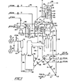
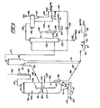
- the apparatus disclosed comprises a progressive flow riser with a ballistic separator at the upper end of the riser for causing a sudden and substantially instantaneous separation of catalyst particles from product vapors.
- the catalyst is then transferred to a stripping vessel for removal of residual hydrocarbons removable in the presence of high temperature steam and/or other stripping gases. Stripped catalyst is then transferred to a two-stage combustor having insufficient oxygen in the first stage to convert all of the carbon to carbon dioxide and an excess of oxygen in the second stage to almost completely burn off the carbon remaining after the first stage.
- the regenerated catalyst particles attain relatively high temperatures in the range of about 704°C (1300 0 F) to 815°C (1500°F) and have very low levels of residual carbon, namely, 0.05 weight percent or less.
- the regenerated catalyst particles are then returned to the bottom of the riser where they are contacted with fresh feedstock.
- the conversion process of the invention is particularly effective in utilizing the CB catalysts for cracking resid containing, carbo-metallic feeds of the type described.
- Fresh oil feed and a diluent, such as steam, are mixed with the hot regenerated cracking catalyst at or near the bottom of the riser, vaporizing and/or fluidizing the feed and diluent substantially instantaneously to form a vaporous suspension that flows rapidly upward to the ballistic separator.
- the temperature and catalyst oil ratio in the suspension is sufficiently severe to convert approximately 50 to 90% of the carbo-metallic oil feed to gasoline per pass and produce relatively high levels of coke on the catalyst.
- the velocity of the suspension combined with ballistic separation is such as to provide very short contact times and avoid overcracking the desired molecular species of the product, notwithstanding the high temperatures and very active catalyst.
- the regenerator also is operated at relatively high temperatures which provides rapid and effective coke removal and the heat necessary for the endothermic riser reaction. In view of the high temperatures, the regenerator configuration is such that the average catalyst hold up time for regeneration is relatively short, namely, on the order of about 3 to 5 minutes or less. Since relatively small amounts of catalyst are held up in other portions of the system, the overall catalyst inventory is significantly low.
- Relatively high oxygen partial pressures are maintained in the regenerator, either in the last stage of multistage regenerators or in a zone immediately upstream of discharge conduits from single stage regenerators to keep heavy metals on the catalyst in their less active oxide form.
- the substantially instantaneous fluidization of the oil feed and the very short residence times employed tend to inhibit reduction of these metals in the riser to their more catalytically active free metal state.
- certain elements such as antimony, may be added to the regenerator or riser to more permanently tie up accumulated heavy metals.
- the large pores and smaller surface areas of the CB catalysts facilitate such metals deactivation reactions.
- the make-up rates at which fresh catalyst must be introduced into the system are well within acceptable limits, namely, in the range of about 0.1 to 3.0 pounds of catalyst per barrel of fresh feed. More particularly process parameters of the invention, together with further particulars on the catalyst and apparatus thereof, are given in the description below of the best mode for carrying out the invention.
- the catalyst of the invention may be used for treating any hydrocarbon feedstock suitable for cracking to lower boiling components or fore reforming or other hydrocarbon conversion processes. It is especially useful for cracking oil feeds containing an appreciable amount of high molecular weight components, for example a feedstock with at least 5 weight percent, preferably at least 10 weight percent, not boiling below 552°C (1025°F). Diffusion limitation problems, in general, become increasingly troublesome with increasing fractions of high molecular weight components in the feedstock. Other factors involved include molecular configuration and the like.
- high molecular weight and/or “heavy” components refer to those hydrocarbon fractions having a normal boiling point of at least 552°C (1025°F) and include non-boiling hydrocarbons, i.e., materials which may not boil under any conditions.
- this procedure gives a relative indication of molecular sizes and provides a useful tool for estimating average molecular sizes and spreads of sizes in feedstocks.
- Such data may be used for selecting the predominant feeder pore sizes and size distribution characteristics of the catalyst to be prepared for given types of feedstocks. This method therefore may be used as the basis for calculating average molecular diameters and ranges of diameters for heavy feeds.
- high boiling hydrocarbon feedstock has a relatively wide range of molecular diameters for the molecules present with significant frequency. For example, the average difference between the lower and higher significant diameters may ° be as high as 250A.
- the ratio of average feeder pore size of the catalyst to average molecular diameter of the 552°C (1025°F) portion of the feedstock be at least about 2, preferably at least about 5.
- the composite catalysts disclosed have a high tolerance both to metals and to coke precursors and these catalysts will economically crack feedstocks containing high concentrations of such contaminants.
- a high metals feedstock for purposes of this invention is one having a heavy metal content of at least about 4 ppm of Nickel Equivalents.
- a high coking feedstock for purposes of this invention is one having a Conradson carbon residue value greater than about 1.
- the feedstocks for which the invention is particularly useful will have a heavy metal content of at least about 5 ppm Nickel Equivalents and a Conradson carbon residue of at least about 2. The greater the heavy metal content and the Conradson carbon residue, the more advantageous the catalyst and process of this invention becomes.
- a particularly preferred feedstock for treatment by the process of the invention includes a reduced crude and comprises 70 percent or more of a 343°F+ (650°F+) material having a fraction greater than 20 percent boiling above 552°C (1025°F) at atmospheric pressure, a metals content of greater than 5.5 ppm Nickel Equivalents and a Conradson carbon residue of greater than 4.
- This feed may have a hydrogen to carbon ratio of less than about 1.8 and coke precursors in an amount sufficient to yield about 4 to 14 percent coke by weight based on fresh feed.
- the feed may be pretreated (but preferably is not) by a hydrotreating step to saturate unsaturated hydrocarbons and/or by contacting adsorbent particles to remove a portion of the poison metals and carbon precursors.
- feedstocks contemplated for use with the invention include whole crude oils, fractions of crude oils such as topped crude, reduced crude, vacuum fractionator bottoms and other fractions containing heavy residua, coal-derived oils, shale oils, waxes, untreated or deasphalted residua, and blends of such fractions with gas oils and the like.
- diluent materials may also be charged to the riser to lower the vapor pressure of the oil feed. Diluents will increase the space velocity of the process by accelerating the velocity of the oil and decreasing catalyst contact time. Any diluent which is a vapor or becomes a vapor under the conditions in the conversion zone can be used. If the diluent is a hydrocarbon, is should desirably have a boiling point below about 343°C (650°F), and more preferably it should be a gasoline range hydrocarbon, e.g. naphtha, or lighter, which fractions boil at about 221°C (430°F) or below.
- diluents include various gases such as hydrogen, nitrogen, methane and ethane, and water, which may be charged either as liquid or steam. Such diluents may be added at or near the bottom of or at one or more locations along the riser conversion zone so as to assist in dispersal and fluidization of the catalyst, dispersal and vaporization of the liquid feedstock, quenching of the catalyst and/or oil suspension, and under some conditions, may increase the cracking rate and/or improve the selectivity of the cracking process.
- the heavy metals may accumulate on the catalyst to levels in the range of from about 3000 to about 20,000 ppm of Nickel Equivalents. Where about 4 to 14 percent of the feedstock is converted to coke, this coke is generally deposited on the catalyst in amounts in the range of about 0.3 to 3.0 percent by weight of the catalysts.
- the present invention includes a method of making a catalyst with a relatively large percentage of pores in size ranges above o 0 100A, preferably in the range of 400 to 6000A, more preferably 1000 0 to 6000A.
- the catalyst is especially useful in the processing of reduced crudes and other heavy feeds.
- the method involves incorporating a relatively large amount of selected carbon black solids into the catalyst matrix material. The carbon black is subsequently removed by converting it to gaseous carbon oxides by oxidation at elevated temperatures.
- Its removal provides a pore 0 volume greater than 0.10 cc/gm in pores greater than 400A, preferably 0.15 cc/gm with at least 0.10 cc/gm in pores greater 0 than 1000A, more preferably at least 0.20 cc/gm with at least 0.15 0 cc/gm in pores greater than 1000A.
- the invention reliably and predictably increases the pore volume comprises of these large pore sizes.
- Carbon black may be added, along with other solids such as zeolite and clay, during the formation of the catalyst matrix material.
- the carbon black may be added after the basic catalytic composition has been prepared but before final drying, as for example, by forming a slurry of prepared catalyst composition followed by dispersing the carbon black within the slurry and then spray drying the resulting suspension.
- Carbon black may also be added to the zeolite component either prior to or during the formation of the aluminosilicate crystals.
- Carbon black differs from other types of carbon, such as charcoal, and from other types of fillers such as flour or cellulose fibers, in that it exists as very small reticulated particles and is substantially non-porous in most of its forms.
- Each reticulated particle is itself comprised of smaller "primary" carbon black particles.
- Primary carbon black particles are essentially spherical, the diameter of the sphere varying depending upon the method of manufacture.
- the primary particles in turn are composed of several thousand microcrystallite bundles stacked together in a random order and each bundle consists of several polynuclear aromatic platelets which are stacked in a not quite parallel manner.
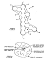
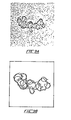
- the carbon blacks of the present invention possess to a greater or lesser extent a basic property called "structure".
- Structure refers to the degree to which the primary particles are bound together into a 3-dimensional primary chain network making up the reticulated particle.
- An idealized reticulated particle of carbon black is illustrated in Figure 1. While not intending to be bound by any one theory, it is believed that the primary particles may be fused together or share common microcrystallite bundles or planes to make up the primary chains.
- This primary reticulated structure is to be distinguished from secondary or reversible structures which result from van der Waals forces between individual reticulated particles.
- Primary carbon black structures exhibit a pronounced tendency to agglomerate into secondary reticulated structures when dispersed in almost all media.
- the carbon black of the present invention is preferably produced in refractory-lined furnace reactors by pyrolysis of highly aromatic refinery by-product oils. These oils are subjected to temperature of about 760°C (1400°F) to 899°C (1650°F) in a reaction zone maintained at conditions producing an endothermic reaction which strips atomic hydrogen from the aromatic hydrocarbon molecules to leave aromatic carbon nuclei. The resulting reticulated particles in the form of a black "smoke" are quenched in a downstream tunnel by water injection at a point several feet from the reaction zone. In this method of manufacturing carbon black, the primary particles size can be closely controlled and produces ° particle diameters in the range of about 200 to 900A.
- These primary particles are simultaneously bound together to form primary reticulated chains having lengths in the range of about 500 to ° 30,OOOA. Both structure and particles size may be closely controlled through the design of the oil injection nozzle, reaction chamber geometry, pyrolysis temperature, residence time, and the intensity of gaseous turbulence.
- carbon black contains less than about half the amount of hydrogen theoretically needed to bond all edge portions of the polynuclear aromatic platelets and it is believed that the particles contain many unsatisfied valences or free radicals.
- the principal surface groups on carbon black have been have been identified in the literature as carboxylic acid, phenolic hydroxyl and quinone groups, and possibly peroxide and lactone groups.
- functional groups at the carbon black surface can also generate free radicals, or at least can initiate free radical reactions. It is believed that these organic functional groups may assist in forming both the unfired catalyst compositions of the present invention.
- carbon black is an amorphous form of carbon as opposed to graphite which is a soft crystalline form of carbon that differs greatly in properties from amorphous carbon.
- the thermal conductivity of amorphous carbon is relatively high and is equivalent to some metals.
- Carbon black also has a very low co-efficient of thermal expansion and a high resistance to thermal shock. It is believed that these features contribute to relatively rapid rates of carbon burnout and large feeder pores of substantially uniform diameter.
- a preferred type of carbon black meets the specifications of ASTM No. N-219. These blacks have relatively low structure and are made using an intermediate super-abrasion furnace. Such blacks are available from Ashland Chemical (United N-210), Cabot (Regal 600), Columbian (Niotex 130), Continental (Continex ISAF-LS), and Phillips (Philblack N-210). United N-219L is preferred as it is not compacted but supplied loose at relatively low bulk density compared to pelleted or compacted blacks.
- the average primary particle diameter of this black is about 0 300A and it has an ASTM Iodine Number of about 115 (a measurement of surface area per unit weight correlating well with nitrogen absorption measurements for furnace blacks).
- the relatively low structure of this black is indicated by a low DBP Absorption value of about 0.78 cubic centimeters per gram (the DBP Absorption value is indicative of the degree of linkage between primary carbon black particles).
- One of the principal objects of the invention is to disperse the carbon black sufficiently in the catalyst forming media so that formation of secondary CB structures through agglomeration of primary CB structures can be significantly controlled.
- Some of the more effective dispersants for carbon black in in aqueous media are hexadecyltrimethylammonium bromide, an ethoxylated alcohol sulfate sold under the brand name Marasperse CBO-3, and mixtures thereof. These dispersants are used in amounts generally proportional to the weight of carbon black added, preferred proportions being in the range of about 0.05 to 1.0 weight percent of carbon black, more preferably about 0.1 percent.
- Quaternary surfactants such as Quaternary O, succinates such as Aerosol, and other ethoxylated alcohol sulfates may also be used.
- the most predominant feeder pore size can be controlled to a significant extent both be the amount of carbon black used and the amount and effectiveness of the dispersant used to suspend the carbon black in an aqueous medium. It is believed that the degree of dispersion versus the degree of agglomeration of the primary reticulated CB particles is a controlling factor in determining whether the predominant feeder pore sizes are in the lower or the upper portion 0 of the preferred pore size range of 500 to 6000A. Thus, lower carbon black concentrations in combination with the most effective dispersants provide an increased number of pores with effective 0 diameters in the range of 400 to 1000A when using primary carbon 0 black particles having an average diameter of about 300A.
- the amount of carbon black used in preparation of the unfired catalyst will therefore depend on the extent to which large feeder pores are desired in the final catalyst structure. Other factors include the final attrition resistance desired. Generally, the amount of carbon black should be in the range of 1 to 35 percent by weight of unfired product. Too little carbon black will not produce a sufficient number of large pores and too much carbon black will result in a catalyst having relatively low attrition resistance. Accordingly, preferred amounts of carbon black are in the range of about 2 to 30 percent by weight, more preferably 5 to 15 percent by weight, of the unfired product.
- the average effective diameter of the hydrocarbon molecules in the feedstock is the statistical average of the largest effective dimension of the molecules boiling above 552°C (1025°F).
- the feeder pores should have an average effective diameter at least equal to this average feedstock dimension, but should not exceed about 10 times this dimension so as not to decrease unduly the surface area and, correspondingly, the number of catalytic sites available for the cracking reaction. Accordingly, the ratio of average feeder pore diameter to average hydrocarbon diameter should be in the range of 2 to 10 more preferably 4 to 8, most preferably 5 to 8.
- the carbon black suspension preferably an aqueous medium
- the carbon black suspension can be mixed uniformly with a catalyst slurry and the resulting composite suspension spray dried to form substantially uniform microspheres within the preferred range of particle sizes described below.
- prior art techniques using a decomposable solid for introducing large pores into a matrix involve the formation and extrusion of a viscous paste which then has to be dried and broken up. This results in catalyst particles having a wide range of diverse shapes and sizes which have to be sifted in order to provide a catalyst of any uniformity.
- the types of decomposable solids used in the prior art produce low activity catalysts with excessively large pores, the pore size range in any given mix being virtually uncontrollable.
- the composite After being intimately mixed with the matrix material and any other ingredients, such as zeolite and/or filler components, the composite is shaped and dried to produce an unfired catalyst composite. This shaped composite is then heated to burn out the carbon black and produce a final catalyst product. containing a significant volume of large feeder pores within the desired size ranges. The temperature experienced by the catalyst particles should not cause objectionable changes in the structure of either the zeolite or the supporting matrix. Where carbon black is removed during manufacture, burn out is initiated at about 260°C (500°F) and the firing time varies in accordance with the temperature selected, higher temperatures requiring shorter firing times.
- the temperature should not exceed about 815°C (1500 0 F) to avoid damage to the zeolite.
- Preferred firing temperatures are in the range of about 538°C (1000 0 F) to 787°C (1450°F), with corresponding firing times from about three hours to as low as a few minutes, such as associated with catalyst hold-up in a regenerator.
- temperatures as high as 1093°C (2000°F) may be tolerated.
- the invention is not restricted to the use of contact agents containing any specific matrix components or catalytic promoter.
- Any matrices and/or promoters of the prior art may be used in combination with carbon black for the production of feeder pores in solid catalysts which may be of any suitable shape and size.
- carbon black may be used to provide feeder pores in synthetic silica-alumina catalysts of the type described in U.S. Patent No. 3,034,994 to Braithwaite, et al, which patent is incorporated herein by reference.
- this or a similar silica-alumina composition as a matrix for supporting a superactive zeolite component.
- a preferred catalyst of the present invention therefore comprises three main components, namely, a catalytically active or inactive matrix material, a superactive catalytic promoter dispersed in the matrix material, and a carbon black initially dispersed in the matrix but removable therefrom by combustion.
- a preferred matrix composition is one having sufficient acid sites to provide significant cracking activity, particularly for the high molecular weight components of the feed. It is therefore a further object of the invention to employ a catalyst matrix in which significant catalysis of the heavy hydrocarbon molecules boiling above 552°C (1025°F) is affected in the feeder pores. Catalysis in these macropores may be affected by acidic sites either in the matrix itself or on exposed outer surfaces of the superactive zeolite. It is believed that conversion and selectivity is significantly improved if these feed components are initially cracked in the matrix to smaller size molecules capable of entering the much smaller zeolite pores. Less reliance on thermal cracking for these types of reactions gives improved product distribution and gasoline yield and better overall product quality, i.e. less methane, ethane, ethylene, thermal coke, thermal gas oil, and thermal gasoline.
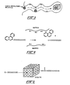
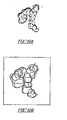
- a catalyst microsphere made according to the invention is illustrated in Figure 2.
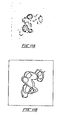
- the mechanism for trapping heavy liquid asphaltenes in the matrix feeder pores so as to reduce the number reaching and blocking zeolitic pores is illustrated in Figure 3.
- Figure 4 shows diagrammatically the cracking of a heavy polynuclear aromatic at an acidic site (H+) in the matrix. The straight chain fragment from the matrix cracking of Figure 4 may then be cracked and reformed by the zeolite as illustrated in Figure 5.
- the matrix material should possess good hyrothermal stability.
- materials exhibiting relatively stable pore characteristics are alumina, silica-alumina, silica, silica-magnesia, magnesia-alumina, silica-zirconia, clays such as kaolin, metakaolin, halloysite, anauxite, dickite and/or macrite, and combinations of these materials.
- Other clays such as natural montmorillonite, synthetic mica montmorillonite (SMM), and/or pillared layered clays (PLC) may be added to increase the acidity of the matrix. Clay may be use in its natural or thermally modified states.
- SMM synthetic mica montmorillonite
- PLC pillared layered clays
- 3,034,994 is a semisynthetic combination of clay and silica-alumina.
- the clay is mostly a kaolinite and is combined with a synthetic silica-alumina hydrogel or hydrosol.
- This synthetic component forms preferably about 15 to 75 percent, more preferably about 20 to 25 percent, of the fired catalyst in weight.
- the proportion_ of clay is such that the catalyst preferably contains after firing about 10 to 75 percent, more preferably about 30 to 50 percent, clay by weight.
- a most preferred composition of the matrix contains approximately twice as much clay as synthetically derived silica, alumina or silica-alumina.
- Synthetically derived silica-alumina should contain 55 to 95 percent by weight of silica (Si02), more preferably about 75 percent.
- the composition is preferably slurried and spray dried to form catalyst microspheres.
- the particles size of the spray dried matrix is generally in the range of about 5 to 160 microns, preferably 50 to gO microns.
- Various processes may be used in preparing the synthetic silica-alumina, such as those described in U.S. Patent No. 3,034,994.
- One of these processes involves gelling an alkali metal silicate with an inorganic acid while maintaining the pH on the alkaline side.
- An aqueous solution of an acidic aluminum salt is then intimately mixed with the silica hydrogel so that the aluminum salt solution fills the silica hydrogel pores.
- the aluminum is thereafter precipitated as a hydrous alumina by the addition of an alkaline compound.
- a silica hydrogel is prepared by adding sulfuric acid with vigorous agitation and controlled temperature and concentration conditions to a sodium silicate solution.
- Aluminum sulfate in water is then added to the silica hydrogen with vigorous agitation to fill the gel pores with the aluminum salt solution.
- An ammonium solution is then added to the gel with vigorous agitation to precipitate the aluminum as hydrous alumina which combines with the silica to produce silica-alumina on the surface of the silica hydrogel, after which the hydrous gel is processed, for instance, by separating a part of the water on vacuum filters and then drying, or more preferably, by spray drying the hydrous gel to produce microspheres.
- the dried product is then washed to remove sodium and sulfate ions, either with water or a very weak acid solution.
- the resulting product is then dried to a low moisture content, usually less than 25 percent by weight, e.g., 10 percent to 20 percent by weight, to provide the finished catalyst product.
- the silica-alumina hydrogel slurry may be filtered and washed in gel form to affect purification of the gel by the removal of dissolved salts. This may enhance the formation of a continuous phase in the spray dried microspheric particles. If the slurry is prefiltered and washed and it is desired to spray dry the filter cake, the latter may be reslurried with enough water to produce a pumpable mixture for spray drying. The spray dried product may then be washed against and given a final drying in the manner previously described. Spray dryable compositions to which carbon black can be added and spray drying techniques usable with the present invention are also described in U.S. Patent No. 3,867,308 to Elliott and U.S. Patent No. 4,126,579 to Flaherty, et al, which patents are incorporated herein by reference.
- Suitable catalytically active promoters other than zeolites may be used and include metals or a catalytic compounds of metals such as Pb, Sn, Bi, Ge, Sc, Ti, Cr, Mn, Co, Zn, Y, Nb, Mo, Ma, Ru, Rh, Pd, La, Hf, Ta, W, Re, Os, Ir, Pt, Zr, Ac, Th, Pa, and U and the like. These components may be used alone or in addition to a superactive zeolite. In the latter case, these elements and/or compounds may increase the catalytically active sites available in the matrix. These additional promoters may be used in concentration ranges generally from about 0.5 percent to about 20 percent, more preferably about 1 to 5 percent by weight of fired catalyst.
- the catalytically active promoter for a preferred catalyst composition is a crystalline aluminosilicate zeolite, commonly known as molecular sieves.
- Molecular sieves are initially formed as alkali metal aluminosilicates, which are dehydrated forms of crystalline hydrous siliceous zeolites.
- the alkali form does not have appreciable activity and alkali metal ions are deleterious to cracking processes, the aluminosilicates are ion exchanged to replace sodium with some other ion such as, for example, ammonium and/or rare earth metal ions.
- the silica and alumina making up the structure of the zeolite are arranged in a definite crystalline pattern containing a large number of small uniform cavities interconnected by smaller uniform channels or pores.
- the effective 0 0 size of these pores is usually between about 4A and 13A.
- the zeolites which can be employed in accordance with this invention include both natural and synthetic zeolites.
- the natural occurring zeolites include gmelinite, clinoptilolite, chabazite, dechiardite, faujasite, heulandite, erionite, analcite, levynite, sodalite, cancrinite, nehpeline, lcyurite, scolicite, natrolite, offretite, mesolite, mordenite, brewsterite, ferrierite, and the like.
- Suitable synthetic zeolites include zeolites Y, A, L, ZK-4B, B, E, F, H, J, M, Q, T, W, X, Z, ZSM-types, alpha, beta and omega.
- zeolites as used herein contemplates not only aluminosilicates but substances in which the aluminum is replaced by gallium and substances in which the silicon is replaced by germanium.
- the zeolite materials utilized in the preferred embodiments of this invention are synthetic faujasites which posses silica to alumina ratios in the range from about 2.5 to 7.0, preferably 3.0 to 6.0 and most preferably 4.5 to 6.0.
- Synthetic faujasites are widely known crystalline aluminosilicate zeolites and common examples of synthetic faujasites are the X and Y types commercially available from the Davison Divison of W. R. Grace and Company and the Linde Division of Union Carbide Corporation.
- the ultrastable hydrogen exchanged zeolites, such as Z-14XS and Z-14US from Davison, are particularly suitable.
- other preferred types of zeolitic materials are mordenite and erionite.
- the preferred synthetic faujasite is zeolite Y which may be prepared as described in U.S. Patent No. 3,130,007 and U.S. Patent No. 4,010,116, which patents are incorporated herein by reference.
- the aluminosilicates of this latter patent have high silica (Si02) to alumina (A1203) molar ratios, preferably above 4, to give high thermal stability.
- a reaction composition is produced from a mixture of sodium silicate, sodium hydroxide, and sodium chloride formulated to contain 5.27 mole percent Si02, 3.5 mole percent Na20, 1.7 mole percent chlorine and the balance water. 12.5 parts of this solution are mixed with 1 part by weight of calcined kaolin clay. The reaction mixture is held at about 16°C (60°F) to 24°C (75°F) for a period of about four days. After this low temperature digestion step, the mixture is heated with live steam to about 88°C (190 0 F) until crystallization of the material is complete, for example, about 72 hours.
- the crystalline material is filtered and washed to give a silicated clay zeolite having a silica to alumina ratio of about 4.3 and containing about 13.5 percent by weight of Na20 on a volatile free basis. Variation of the components and of the times and temperatures, as is usual in commercial operations, will produce zeolites having silica to alumina mole ratios varying from about 4 to about 5. Mole ratios above 5 may be obtained by increasing the amount of Si02 in the reaction mixture. The sodium form of the zeolite is then exchanged with polyvalant cations to reduce the Na20 content to less than about 5 percent by weight, and preferably less than 1.0 percent by weight.
- the carbon black ingredient of the present invention may be admixed with the zeolite forming composition prior to crystallization of the zeolite and the carbon black component later burned out to form large feeder pores between the zeolite crystals in the resulting agglomerate.
- the zeolites and/or other promoters can be suitably dispersed in matrix.
- materials for use as cracking catalysts by methods well-known in the art, such as those disclosed, for example, in U.S. Patent Nos. 3,140,249 and 3,140,253 to Plank, et al; U.S. Patent No. 3,660,274 to Blazek, et al; U.S. Patent No. 4,010,116 to Secor, et al; U.S. Patent No. 3,944,482 to Mitchell, et al; and U.S. Patent No. 4,079,019 to Scherzer, et al; which patents are incorporated herein by reference.
- the amount of zeolitic material dispersed in the matrix based on the final fired product should be at least about 10 weight percent, preferably in the range of about 25 to 40 weight percent, most preferably about 35 to 40 weight percent. More than one type of zeolitic particles, such as zeolites with different functions and/or selectivities, and zeolitic particles in combination with particles of metals or other catalytic materials may be employed together to make up these amount of total promoter ingredient. For example, particles of hydrodesulfurizing catalyst as in U.S. Patent No. 3,770,617 may be mixed with particles of cracking catalyst as in 4,010,116. The upper ranges of zeolite concentrations, together with a much less but significantly active matrix, are preferred to provide a catalyst with ultrahigh cracking activity even at large pore volumes and relatively low surface areas.
- Crystalline aluminosilicate zeolites exhibit acidic sites on both interior and exterior surfaces with the largest proportion of total surface area and cracking sites being internal to the particles within the crystalline micropores. These zeolites are usually crystallized as regularly shaped, discreet particles of approximately 0.1 to 10 microns in size and, accordingly, this is the size range normally provided by commercial catalyst suppliers.
- the particle size of the zeolites for the present invention is preferably in the range of less than 0.1 to about 1 micron and more preferably in the range of less than 0.1 micron.
- the preferred zeolites are thermally stabilized by heating to temperatures of at least 538°C (1000°F) and then further exchanged with hydrogen ions and/or rare earth ions. These zeolites are steam stable to about 899°C (16500F).
- Feeder pore content of the catalyst within the size range of 0 about 400 to 6000A is provided in the main by the preparative ° method of the invention. Macropores of less than 400A may be produced by this method and may also be introduced into the catalyst matrix by prior art methods for preparing such matrices.
- the micropore content of the catalyst in the size range below 20A is provided principally by the zeolite particles per se.
- micropore content of the catalyst will be variable by a similar amount.
- the fraction of total pore volume provided by micropores ° of 20A or less also will vary depending upon the fraction of large feeder pores introduced by the carbon black component.
- the surface area of the zeolitic component in the catalyst may be estimated by multiplying the surface area of the pure zeolite (usually about 800 to 900 m 2 /gm) by the percentage of zeolite in the final catalyst.
- Total pore volume including the feeder pore volume of the matrix should be at least 0.2 cc/gm, preferably more than 0.4 cc/gm.
- the upper limit for total matrix pore volume is best expressed as the amount of contact surface area provided in the final catalyst matrix. In general, the minimum surface area of a satisfactory catalyst matrix is about 20 square meters per gram, preferably at least 30 square meters per gram, more preferably at least 40 square meters per gram.
- MAT microactivity test
- the microactivity test and standard procedures for obtaining "MAT Activity” are described below. Because the MAT test range is appropriate for equilibrium (used) zeolite catalyst instead of virgin (unused) catalyst, virgin catalyst of the present invention is treated with 97-100% steam at 787°C (1450°F) for 5 hours to provide a standard reduction in its activity before it is tested by the MAT procedure.
- This slurry was mixed for 30 minutes with a Premier High Viscosity Dispersator and then 23.4 gm of rare earth zeolite was added, along with 5 ml of PQ N-Brand sodium metasilicate as a dispersant for the clay and zeolite.
- the resulting slurry was mixed for an additional 30 minutes with the Dispersator and then 120 ml of sodium metasilicate and 200 ml of water were added with mixing for 10 more minutes. 180 ml of a 11.5 wt% sulfuric acid solution were added slowly while mixing continued to partially neutralize the slurry and precipitate silica gel.
- This silica gel contained uniformly dispersed carbon black and clay and was aged for 1 hour at 43°C (110°F) to increase the size of interstitial cavities within the gel. Mixing was then resumed and a 18 wt% solution of aluminum sulfate, prepared from 108.4 gm Al2(SO4)3:18H2O and 200 ml of water at 49°C (120°F), was added to the silica gel and mixing continued for 15 minutes at 43°C (110°F). This slurry was then neutralized by adding 68 ml of concentrated NH40H to precipitate alumina gel.
- the silica and alumina gel mixture was filtered and the resulting gel cake washed three times with 3L of water at 66°C (150°F).
- the washed gel cake was then dried at 260°C (500°F) for 16 hours and the dried cake ground into small solid particles. These particles were then exchanged at 93°C (200°F) for 1 hour with 1L of 1.0M rare earth chloride solution.
- the exchanged particles were filtered and washed three time with 2L of water at 66°C (150°F) and dried at 260°C (500°F) for 16 hours.
- the carbon black was burned out by firing the catalyst particles in air at 538°C (1000°F) until the catalyst became white in color (about 3 hours).
- This procedure produced about 100 gm of dry catalyst particles consisting essentially of 20 wt% zeolite and 20 wt% clay substantially uniformly dispersed in 60 wt% of a silica-alumina matrix containing about 75wt% Si02.
- Example 1 The quantity of carbon black used in Example 1 above provided about 2 wt% carbon black in the unfired catalyst composite.
- Examples 2-5 the same preparation procedure was followed but the amount of carbon black was changed to 4.3, 11.6, 27.1 and 44.6 gms giving a carbon black wt% in the unfired composites of 4, 10, 20, and 30, respectively.
- the amounts of the other ingredients remained the same except that the amount of carbon black dispersant was varied in proportion to the amount of black used.
- the weights of hexadecyltrimethlyammonium bromide and Triton X-100 used in these examples were each approximately 1% of the weight of carbon black added to the deionized water.
- the catalyst samples of Examples 6 throug 9 were prepared following the same basic procedure of Examples 1 through 5 except the amount of clay was increased and the amount of silica and alumina gel decreased so that the amounts of clay and of silica-alumina gel were approximately equal in the final fired product, with the resulting silica-alumina matrix containing about 75 wt% Si02.
- the final neutralized slurry was spray dried to form microspheres of catalyst. These microspheres were then washed, exchanged with rare earth chloride solution, rewashed, and dried at 149°C (300°F) for 16 hours in a manner similar to the gel cake and ground particles of Examples 1-5. Spray drying produces smaller and more uniform particle sizes than grinding gel cake and is preferred for providing a more niform and fluidizable catalyst.
- the average size of the spray dried particles is preferably within the range of about 40 to 80 microns.
- the changes in pore volume produced by the carbon black of Examples 6 through 9 are given in Table 2.
- the changes in pore voume were measured relative to a fired control sample containing no carbon black instead of the unfired type of control sample forming the basis for the comparison in Table 1.
- the changes in porosity exhibited by the samples of Table 2 are consistent with those of Table 1 in that the use of carbon black ° ° increased catalyst porosity in the ranges above 400A and 1000A. However, no significant increase in porosity occurred in the 40 to ° 80A range, the reason for this reason for this variance with the data Table 1 being uncertain at the present time.
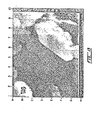
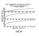
- the curves of Figure 6 suggest that the maximum number of 0 feeder pores having diameters in the range of about 100 to 6000A occur with 18 to 19 wt% carbon black in the unfired catalyst composite.
- This amount of carbon black which equals about 50% by weight of the dry silica-alumina gel in the unfired composite, 0 increases the volume of pores having diameters greater than 100A by about 0.3 cc per gm.
- a carbon black concentration of about 11 wt% in the unfired composite which is about 30% by weight of the silica-alumina gel present, provides the maximum number of 0 feeder pores in the 100 to 1000A range. This corresponds to an increase in pore volume of about 0.1 cc per gm.
- the curves of Figure 6 further indicate that there is an optimum carbon black concentration to attain maximum porosity in a given pore size range and that lower concentrations are required to give the maximum porosity for smaller diameter pores.
- the pore sizing attainable with carbon black is closely related to the degree to which individual reticulated carbon black particles are separated from each other and dispersed within the silica-alumina matrix, full dispersion becoming more difficult to attain and maintain as concentrations of carbon black in the gel slurry increase.
- more effective carbon black dispersants also increase the proportion of pore sizes in the smaller diameter ranges of feeder pores.
- One example of a more effective dispersant for carbon black is sodium lignosulfonate which may be used in place of hexadecyltrimethlammonium bromide and/or Triton X-100 dispersants, particularly where more feeder pore diameters approximating the diameter of primary carbon black particles are desired.
- Lignin is derived from wood pulp and varies in molecular weight between 1000 and 50,000. It's basic organic structural unit is a substituted phenylpropane. Lignin dispersants are commercially available under the name Marasperse which is a sodium lignosulfonate of relatively low sulfonation. While not intending to be bound by any one theory or hypothesis, the action of lignin as a dispersant is believed to be electrochemical in nature. When lignin molecules are adsorbed on the solid carbon black or clay particles in aqueous suspension, they impart a negative charge to the particles, causing them to repel each other.
- Adsorption of lignin molecules on a particle may also create a film which then acts as a physical barrier against direct contact between the particle and the surrounding aqueous media, including silica colloids. These effects are believed to contribute to the production of feeder pore sizes corresponding generally to the transverse diameters of primary reticulated carbon black particles and to improved pore size control.
- Sodium lignisulfonate is a preferred dispersant for carbon black in the catalyst composition of the invention and is added to the matrix slurry with the carbon black prior to the spray drying or other forming step for shaping the solid catalyst particles.
- the catalyst compositions containing lignin and the processes for making those compositions are attributed to William P. Hettinger, Jr., James E. Lewis and H. Wayne Beck, all of Ashland Oil, Inc.
- a slurry of NaY zeolite made from 4 liters of 2pH H20 and 4 kg of zeolite was quickly added to the homogenizer and mixed for 10 minutes.
- the resulting slurry was immediately spray dried at 400°C inlet and 125°C outlet temperatures in a Niro Atomizer Model V Spray Drier to form catalyst microspheres. Air pressure was 30 psig.
- One kilogram of the microspheres from the spray drier was washed three times with 4 liters of 66°C (150°F) water filtered.
- the filter cake was exchanged twice with 3 liters of 1.25 Molar NH3CI for 15 minutes each at 66°C (150°F).
- Samples 11 and 11R were prepared by the same procedure except twice as much carbon black was used, the designation "R” meaning regenerated (fired) to burn out the carbon black particles.
- the fired microspheres are further exchanged after firing with a 0.5N solution of mixed rare earth chlorides at 66°C (150°F) for 30 minutes, and then washed 4 times with 66°C (150 0 F) water and dried for 16 hours at 149°C (300°F).
- the firing step to remove carbon black also calcines the zeolite in the composition. This calcination in combination with the further ion exchange provides an ultrastable, hydrothermally resistant zeolite catalyst. A portion of Sample 11R was further exchanged in this manner to produce Sample 11RE shown in Table 5.
- Table 5 gives some of the catalytic properties of Samples 10R, 11R and 11RE as compared to the Davison catalyst.
- the data given was determined by a micro-activity test (MAT) based on the procedure found in ASTM test method no. D-3908-80 which is described in more detail below.
- MAT micro-activity test
- an FCC type feed is used in this standard test so that it is not fully indicative of the performance of the catalyst samples with a carbo-metallic feed, the data is believed to show the advantage of the invention in reducing the carbon make.
- the carbon producing factor (CPF as defined below) and the weight percent coke (relative to feed weight) are significantly lower for Samples 10R, 11R and 11RE of the invention relative to the Davison catalyst as seen in Table 5.
- Sample Nos. 12 and 13 were prepared following the preparation procedure described above for Sample No. 10, but without the addition of carbon black. These samples yielded MAT volume percent conversions of 73.5 and 79.7, respectively, and carbon producing factors (CPF) of 0.92 and 0.84, respectively, with zeolite intensities of 7.3 and 12.5, respectively.
- CPF carbon producing factors
- the catalyst of the invention has a relatively high level of cracking activity and is capable of providing high levels of conversion and selectivity at low residence times in the riser.
- the conversion capabilities of the catalyst may be expressed in terms of the conversion produced during actual operating of an RCC cracking or other conversion process and/or in terms of conversion produced in standard catalyst activity tests.
- conversion is expressed as liquid volume percent based on volume of fresh feed. Conversion is the volume percentage of feedstock that is converted to 221°C (430°F) endpoint gasoline, lighter products and coke, and is calculated by subtracting from 100 the volume percentage of those products heavier than the gasoline which remain in the recovered product.
- the preferred catalyst may be defined as one which, in its virgin or equilibrium state, exhibits a specified activity expressed as a percentage in terms of MAT (micro-activity test) conversion.
- the foregoing percentage is the volume percentage of standard feedstock which a catalyst under evaluation will convert to 221°C (430°F) end point gasoline, lighter products and coke at 482°C (900°F), 16 WHSV (weight hourly space velocity), and 3 C/O (catalyst to oil weight ratio) using the equipment and procedures specified by ASTM D-32 MAT test D-3908-80 and an appropriate standard FCC feedstock.
- the WHSV is calculated on a moisture free basis using clean catalyst which has been dried at 593°C (1100°F), weighed and then conditioned for a period of at least 8 hours at about 25°C and 50% relative humidity, until about one hour or less prior to contacting the feed.
- the feedstock is preferably a sweet light primary gas oil, such as that used by the Davison Divison of W.R. Grace and defined as follows:
- the gasoline end point and the boiling temperature volume percentage relationships of the products produced in the MAT conversion test may be determined by simulated distillation techniques, for example by modification of the gas chromatographic "Sim-D" technique of ASTM D-2887-73. The results of such simulations are in reasonable agreement with the results obtained by subjecting larger samples of material to standard laboratory distillation techniques.
- the catalyst may be introduced into the process of the invention in its virgin form or in other than its virgin form, e.g., one may use equilibrium catalyst withdrawn from another unit such as catalyst that has been employed in the cracking of an FCC feed.
- equilibrium catalyst withdrawn from another unit such as catalyst that has been employed in the cracking of an FCC feed.
- the preferred catalysts may be described on the basis of their activity "as introduced” into the process of the present invention, or on the basis of their "as withdrawn” or equilibrium activity in the process of the present invention, or on both of these bases.
- a preferred activity level of virgin and non-virgin catalyst "as introduced” into the process of the present invention is at least about 50%, preferably at least about 60% by MAT conversion. However, it will be appreciated that, particularly in the case of non-virgin catalysts supplied at high addition rates, lower activity levels may be acceptable.
- An acceptable "as withdrawn” or equilibrium activity level of catalyst which has been used in the process of the present invention is at least about 50% and an activity level of 60% or more on a MAT conversion basis is also contemplated. More preferably, it is desired to employ a catalyst which will, under the conditions of use in the unit, establish an equilibrium activity at or above the indicated levels. Catalyst activities are determined with the catalyst having less than 0.01 coke, i.e., fully regenerated catalyst.
- CPF Carbon Producing Factor
- HPF Hydrogen Producing Factor and is defined as the ratio of the amount of hydrogen produced by a standard catalyst at the same conversion level.
- the standard catalyst is chosen from among conventional FCC catalysts, such as for example, zeolite fluid cracking catalysts, and is chosen for its ability to produce a predetermined level of conversion in a standard feed under the conditions of temperature, WHSV (weight hourly space velocity), catalyst to oil ratio and other conditions set forth in the preceding description of the MAT conversion test and in ASTM D-32 MAT test D-3907-80.
- relative activity is a ratio obtained by dividing the weight of a standard or reference catalyst which is or would be required to produce a given level of conversion, as compared to the weight of an operating catalyst (whether proposed or actually used) which is or would be required to produce the same level of conversion in the same or equivalent feedstock under the same or equivalent conditions.
- Said ratio of catalyst weights may be expressed as a numerical ratio, but preferably is converted to a percentage basis.
- a "standard catalyst curve" a chart or graph of conversion (as above defined) vs. reciprocal WHSV for the standard catalyst and feedstock.
- a sufficient number of runs is made under ASTM D-3907-80 conditions (as modified above) using standard feedstock at varying levels of WHSV to prepare an accurate "curve" of conversion vs. WHSV for the standard feedstock.
- This curve should transverse all or substantially all of the various levels of conversion including the range of conversion within which it is expected that the operating catalyst will be tested. From this curve, one may establish a standard WHSV for test comparisons and a standard value of reciprocal WHSV corresponding to that level of conversion which has been chosen to represent 100% relative activity in the standard catalyst.
- the aforementioned reciprocal WHSV and level of conversion are, respectively, 0.0625 and 75%.
- relative activity curve was developed utilizing a standard catalyst of 75 vol% conversion to represent 100% relative activity. One such curve is shown in Figure 14.
- a relative activity of 0.5, or 50% means that it would take twice the amount of the operating or test catalyst to give the same conversion as the standard catalyst, i.e., the production catalyst is 50% as active as the reference catalyst.
- the relative activity level of virgin and non-virgin catalyst "as introduced" into the process of the present invention is at least about 20%, preferably at least about 40% and more preferably at least about 60%. However, it will be appreciated that, particularly in the case of non-virgin catalysts supplied at high addition rates, lower activity levels may be acceptable.
- An acceptable "as withdrawn” or equilibrium relative activity level of catalyst which has been used in the process of the present invention is at least about 20% or more, preferably about 40% or more, and more preferably about 60% or more. More preferably, it is desired to employ a catalyst which will, under the conditions of use in the unit, establish an equilibrium activity at or above the indicated levels.
- the individual reticulated CB particle “R” is made up of a series of primary particles "P" of roughly spherical shape held together by atomic and/or interfacial binding forces. Attached to a central chain C-C are a number of side chains Sl, S2 and S3, the actual number of side chains varying from particle to particle and the extent of such branching being indicated by a "branching factor", such as given in Figure 9B through 12B.
- the diameter of the particle P determines the transverse diameter of the central chain 0 C-C and is usually about 100 to 1000A, preferably about 300 to 0 600A.
- the length of the longest chain such as from point L to 0 point M in Figure 1, is usually about 500 to 30,OOOA, preferably 0 1000 to 10,000A.
- the average length to diameter ratio for such particles is preferably in the range of 2 to 5 or greater. It is believed that such reticulated particles yield feeder pores roughly of the same dimensions as illustrated by the dotted outline of a feeder pore F in Figure 1.
- central chain and these side chains are believed to overlap with those of adjacent reticulated particles and thereby provide correspondingly tortuous channels and feeder pore branches in the matrix leading to the zeolite particles supported therein.
- two or more reticulated particles may adhere closely together to form an agglomerate mass so that the resulting pore size corresponds to the dimensions of this mass.
- Such agglomerates are 0 believed to produce pore sizes of 1000A and greater.
- the degree of agglomeration depends not only upon the particular dispersant used, but also upon the mixing means used and the mixing energy imparted to the carbon black suspension and resulting catalyst slurry.
- a greater percentage of pore sizes in the range of 400 to 0 600A may be realized with catalyst compositions similar to those of Examples 1 to 9 but using increased agitation in combination with lignosulfonate as the dispersant.
- FIG. 9A A scanning electron microscope (SEM) was used to make micrographs of some of the carbon black particles useful in the catalyst of the present invention. Copies of those micrographs are presented in Figures 9A, 10A, 11A and 12A. Contour plots were also prepared of these reticulated carbon black particles by plotting the particle contours with an X-Y recorder attached to a computer read-out from photogrammetric topography. The contour plots, together with tables of topographical measurements for each particle, are presented in Figures 9B, 10B, 11B and 12B which correspond to carbon black types N-339, N-550, N-220 and N-326 shown in Figures 9A-12A, respectively.
- Figure 13 is a photograph showing a catalyst matrix from which the carbon black has been removed, the catalyst composition having been made and fired in accordance with the teaching of the invention.
- the photograph has been marked with horizontal coordinates 1 through 10 and vertical coordinates A-H.
- the dark areas of the photograph are pores and the horizontal and vertical coordinates may be used to identify the location of those pores.
- the location and approximate size of the minor transverse dimension of some of the carbon black pores are identified as follows: Dl-2, 0 0 0 0 0 300A, G4, 1500A, B6-7, 250A, C7-8, 700A; D9, 600A.
- the scale of this photograph is in micrometers (microns), one-tenth of a micrometer being equal to 1000 Angstroms units.
- the dimensional units of Figure 13 are comparable to those of Figures 9 through 12 where the scale is in nanometers (nm), one nanometer being equal to ten Angstrom units.
- the catalyst is particularly useful in the catalytic cracking of residuum or carbo-metallic oil feeds.
- the catalytic cracking operation may be conducted in various types of reactors and associated equipment, such as fixed bed systems or fluidized systems.
- the catalyst is particularly useful in a fluidized bed type of operation where the catalyst in a finely divided fluidized state is suspended in vaporized feedstock and the suspension of catalyst and feedstock is passed upward through an elongated riser in a progressive flow arrangement without significant backmixing.
- riser operations are carried out at conditions conducive to achieving the improved results desired, bearing in mind the specific feedstock, catalyst composition and process equipment being used.
- the process is preferably carried out without added hydrogen.
- FIG. 7 is a schematic diagram of one apparatus for carrying out the process of the present invention.
- the carbo-metallic oil feed is supplied through a feed supply pipe 10 having a control valve 11 to a wye 12 in which the feed is mixed with a flow of catalyst delivered through a catalyst supply pipe 13 as controlled by a valve 14.
- water or some other diluent may be introduced to the wye through a diluent supply pipe 9.
- the mixture of catalyst and feed, with or without additional diluent materials, then flows upward through a riser reactor 18.
- the riser 18 is an elongated conduit in which the length to diameter ratio may vary widely.
- the relatively narrow riser conduit provides high linear velocities, such as in the range of 25 to 90 feet per second.
- the length to diameter ratio of the riser is preferably in the range of 10 to 30, more preferably 20 to 25.
- chamber 19 At the upper end of riser 18 is a chamber 19 which receives catalyst from the riser. While chamber 19 may be a conventional disengagement and collection chamber, often referred to as a reactor vessel, it is preferred that means be provided at the riser exit for causing product vapors to undergo a rapid change of direction relative to the direction traveled by the catalyst particles so that the vapors are suddenly or "ballistically" separated from the catalyst particles.
- disengagement chamber 19 of Figure 7 is an upward extension 20 of riser pipe 18 having an open top 21 through which the catalyst particles are discharged. The product vapors are caused to undergo a sudden change of direction into lateral port 22 in the side of riser extension 20, the catalyst particles because of their momentum being, for the most part, unable to follow the product vapors into port 22.
- This embodiment of the cracking apparatus makes use of the vented riser concept described in U.S. Patent Nos. 4,066,533 and 4,070,159 to Myers, et al, which patents are incorporated herein by reference.
- the vented riser thus provides a substantially instantaneous separation between hydrocarbon and catalyst in disengaging vessel 19. Because of the relatively high severity required to crack the more refractory components of carbo-metallic feeds, rapid disengagement of catalyst from cracked hydrocarbons by ballistic separation prevents overcracking of desirable liquid products, such as gasoline, to light undesirable products, such as hydrogen and methane gases and carbon.
- the product vapors and a relatively small amount of catalyst entrained with them are transferred by a cross pipe 23 to a cyclone separator 24 for removing the entrained catalyst.
- the cyclone separator 24 may be connected via a transfer pipe 17 to an optional secondary cyclone separator 25.
- Product vapors are discharged from disengagement chamber 19 through overhead product discharge pipe 26.
- Catalyst spilling over from the bottom of disengagement 19 passes via a drop leg 31 into a stripping chamber 32 equipped with baffles 33 and a steam jet 34.
- Other stripping gases known in the art may be introduced through jet 34 and employed with or in place of steam.
- Accumulated carbon is burned from the catalyst in a combustor 38 which receives stripped catalyst via a downcomer pipe 39 with a control valve 40.
- Combustion air is supplied from an air supply system, generally indicated by 44 and including blowers 41 and 42 and filter bank 43, to combustion air jets 48 at the bottom of the combustor and to fluffing air jets 49 at an elevated position therein.
- Regenerated catalyst with most of the carbon burned off, departs the combustor 38 through an upper outlet 50 and cross pipe 51 to a secondary combustion chamber 52, where it is deflected into the lower portion of chamber 52 by baffle 53.
- the secondary chamber 52 is operated primarily as a separator chamber for separating regenerated catalyst from combustion gases. Additional oxygen containing gas may be introduced through lines 59 and secondary chamber 52 operated with an excess of oxygen to insure removal of carbon deposits down to residual carbon levels of 0.05 weight percent or less.
- Catalyst may optionally move in up to three different directions from secondary chamber 52.
- Fully regenerated catalyst is discharged through bottom outlet 69 to catalyst supply pipe 13 through which it is recirculated to wye 12 for contact with fresh feed as previously described.
- a portion of the hot catalyst may be circulated back to combustor 38 via catalyst recirculation line 55 with control valve 56 for heat control in the combustor and to raise the temperature of incoming air with hot catalyst so as to insure that combustion of coked catalyst is properly initiated.
- two sets of primary and secondary cyclones are provided in chamber 52 for separating these catalyst fines from the combustion gases.
- Catalyst collected in cyclones 57, 58 is discharged through their dip legs to the bottom of chamber 52 where the catalyst is kept in suspension by air, inert gas and/or steam from lines 59 and by a baffle arrangement 54.
- Combustion product gases produced by regeneration of the catalyst and separated from entrained catalyst fines are discharged through effluent pipes 61, 62 and heat exchangers 60, 63. If such gases contain sufficient amounts of carbon monoxide, they may be sent via gas supply pipe 64 to an optional CO boiler 65 in which the CO is burned in order to heat heating coil 66 connected with a steam boiler 67.
- control valve 14 which is preferably a type of slide valve operated by suitable automatic control equipment (not shown) responsive to the temperature of product vapors downstream of riser outlet 22. If additional heat removal from the combustion chambers is required, conventional direct or indirect cooling techniques may be employed in the manner known to persons skilled in the art of designing and operating regenerators.
- the preferred conversion reactor is of the progressive flow type and is operated so that no dense bed of catalyst builds up within the riser, space velocities in the riser are usually high and will generally fall within the range of about 100 to 600 weight of hydrocarbon per hour per instantaneous weight of catalyst occupying the riser volume. In the absence of significant catalyst build up, the instantaneous catalyst inventory within the riser volume if represented by the catalyst particles suspended with the oil feed.
- FIG. 8 A particularly preferred embodiment if described in Figure 8 where reference numeral 80 identifies a feed control valve in feedstock supply pipe 82.
- Supply pipe 83 (when used) introduces liquid water into the feed.
- Heat exchange 81 in supply pipe 82 acts as a feed preheater, whereby preheated feed material may be delivered to the bottom of riser type reactor 91.
- Catalyst is delivered to the reactor through catalyst standpipe 86, the flow of catalyst being regulated by a control valve 87 and suitable automatic control equipment (not shown) with which persons skilled in the art of designing and operating riser type cracking units are familiar.
- the reactor is equipped with a disengagement chamber 92 similar to the disengagement chamber 19 of the reactor shown in Figure 7. Catalyst departs disengagement chamber 92 through stripper 94. Spent catalyst passes from stripper 94 to regenerator 101 via spent catalyst transfer pipe 97 having a slide valve 98 for controlling flow.
- Regenerator 101 is divided into upper chamber 102 and lower chamber 103 by a divider panel 104 intermediate the upper and lower ends of the regenerator.
- the spent catalyst from transfer pipe 97 enters upper chamber 102 in which the catalyst is partially regenerated.
- a funnel-like collector 106 having a bias-cut upper edge receive partially regenerated catalyst from the upper surface of the dense phase of catalyst in upper chamber 102 and delivers it via drop leg 107 having an outlet 110 beneath the upper surface of the dense phase of catalyst in lower chamber 103.
- drop leg 107 instead of internal catalyst drop leg 107, one may use an external drop leg. Valve means in such external drop leg can control the residence time and flow rate in and between the upper and lower chambers.
- Air is supplied to the regenerator through an air supply pipe 113. A portion of the air travels through a branch supply pipe 114 to bayonet 115 extending upwardly in the interior of plenum 111 along its central axis. Catalyst in chamber 103 has access to the space within plenum 111 between its walls and bayonet 115. A small bayonet (not shown) in the aforementioned space fluffs the catalyst and urges it upwardly toward a horizontally arranged ring distributor (not shown) where the open top of plenum 111 opens into chamber 103.
- air heater 117 at least during start-up with VGO
- inlet 118 of the ring distributor which may be provided with holes, nozzles or other apertures which produce an upward flow of gas to fluidize the partially regenerated catalyst in chamber 103.
- the air in chamber 103 completes the regeneration of the partially regenerated catalyst received via drop leg 107.
- the amount of air supplied so that the resultant combustion gases are still able to support combustion upon reaching top of chamber 103.
- Drop leg 107 extends through an enlarged aperture in panel 104, to which is secured a gas distributor 120 which is concentric with and surrounds the drop leg.
- Combustion supporting gases which have been partially depleted, are introduced via gas distributor 120 into upper regenerator chamber 102 where they contact incoming coked catalyst from coked catalyst transfer pipe 97.
- Apertured probes 121 in gas distributor 120 assist in achieving a uniform distribution of the partially depleted combustion supporting gas into upper chamber 102.
- Supplemental air or cooling fluids may be introduced into upper chamber 102 through a supply pipe 122, which may discharge through gas distributor 120.
- regenerator not only smooths out variations in catalyst regenerator residence time but is also uniquely of assistance in restricting the quantity of regeneration heat which is imparted to the fresh feed while yielding a regeneration catalyst with low levels of coke and/or carbon black for return to the riser.
- the high oxygen concentration and temperature in chamber 103 combine to rapidly remove the remaining carbon in the catalyst, thereby achieving a clean, regenerated catalyst with a minimum of heat release.
- the combustion temperature and CO to C02 ratio in the lower chamber are readily controlled.
- the regeneration off gases are discharged from upper chamber 102 via gas pipe 123, regulator valve 124, catalyst fines trap 125 and outlet 126.
- the vapor products from disengagement chamber 92 may be processed in any convenient manner such as by discharge through vapor line 131 to fractionator 132.
- Fractionator 132 includes a bottoms outlet 133, side outlet 134, flush oil stripper 135, and stripper bottom line 136 connected to pump 137 for discharging flush oil.
- Overhead product from stripper 135 returns to fractionator 132 via line 138.
- the main overhead discharge line 139 of the fractionator is connected to receiver 142 having a bottoms line 143 feeding into pump 144 for discharging gasoline product. A portion of this product may be returned to the fractionator via recirculation line 145, the flow being controlled by valve 146.
- the receiver also includes a water receiver 147 and a water discharge line 148.
- the gas outlet 150 of the overhead receiver discharges a stream which is mainly below C5, but containing some C5, C6 and C7 material. If desired, the C5 and above material in the gas stream may be separated by compression, cooling and fractionation, and recycled to receiver 142.
- the oxidizing gas, such as air, introduced into regeneration zone 103 through line 114 may be mixed with a cooling spray of water from a conduit 109.
- the mixture of oxidizing gas and atomized water flows through bayonet 115 and thus into the lower bed of catalyst particles.
- the apertures in distributor 120 are large enough so that the upwardly flowing gas readily passes therethrough into zone 102. However, the perforations are sized so that the pressure difference between the upper and lower zones prevents catalyst particles from passing downwardly through the distributor.
- the bayonet 115 and distributor are similarly sized. Gases exiting the regenerator comprise combustion products, nitrogen, steam formed by combustion reactions and/or from vaporizing water added with the oxidizing gas, and oxides of sulfur and other trace elements. These gases are separated from suspended catalyst particles by a cyclone separator (not shown) and then pass out of the regenerator through discharge conduit 123.
- the catalysts described in this specification may be employed in the processes and apparatuses for carbo-metallic oil conversion described in co-pending U.S. applications serial nos. 94,091; 94,092; 94,216; 94,217 and 94,277 of Ashland Oil, Inc., each of said co-pending applications having been filed on November 14, 1979, and being expressly incorporated herein by reference.
- a preferred method for cracking feeds with heavy fractions referred to as Reduced Crude Conversion (RCC) after a particularly common and useful carbo-metallic feed, is disclosed in co-pending application USSN 94,216 filed on November 14, 1979, for "Carbo-metallic Oil Conversion", which application is incorporated herein by reference.
- the preferred feeds capable of being cracked by this method are comprised of 100 percent or less of the 343°C+ (650°F+) material previously described.
- the cracking reaction according to the method disclosed in USSN 94,216 is sufficiently severe to convert 50 to 90 percent of the carbo-metallic oil feed to gasoline per pass and produce coke in amounts of 4 to 14 percent by weight based on weight of fresh feed. This coke is laid down on the catalyst in amounts in the range of about 0.3 to 3 percent by weight of catalyst, depending upon the catalyst to oil ratio (weight of catalyst to weight of feedstock) in the riser.
- the feed, with or without pretreatment, is introduced as shown in Figure 7 into the bottom of the riser along with a suspension of hot cracking catalyst prepared in accordance with this invention.
- Steam, naphtha, water and/or some other diluent is preferably introduced into the riser along with the feed.
- These additives may be from a fresh source or may be recycled from a process stream in the refinery. Where recycle additive streams are used, they may contain hydrogen sulfide and other sulfur compounds which may help passivate adverse catalytic activity by heavy metals accumulating on the catalyst.
- the water additive may be introduced either as a liquid or as steam. Water is added primarily as a source of vapor for accelerating the feed and catalyst to achieve the vapor velocity and residence times desired. Other diluents as such need not be added but where used, the total amount of diluent specified includes the amount of water used. Extra diluent would further increase the vapor velocity and further lower the feed partial pressure in the riser.
- the feed As the feed travels up the riser, it is catalytically cracked to form basically five products known in the industry as dry gas, wet gas, cat naphtha, light cycle oil, and heavy cycle and/or slurry oil.
- the catalyst particles are ballistically separated from product vapors as previously described.
- the catalyst which then contains the coke formed in the riser is sent to the regenerator to burn off the coke and the separated product vapors are sent to a fractionator for further separation and treatment to provide the five basic product indicated.
- the regenerating gas may be any gas which can provide oxygen to convert carbon to carbon oxides. Air is highly suitable for this purpose in view of its ready availability. The amount of air required per pound of coke for combustion depends upon the desired carbon dioxide to carbon monoxide ratio in the effluent gases and upon the amount of other combustible materials present in the coke, such as hydrogen, sulfur, nitrogen and other elements capable of forming gaseous oxides at regenerator conditions.
- the regenerator is operated at temperatures in the range of about 538 to 871°C (1000 to 1600°F), preferably 690 to 787°C (1275 to 1450°F), to achieve adequate combustion while keeping catalyst temperatures below those at which significant catalyst degradation can occur.
- it is necessary to control the rate of burning which in turn can be controlled at least in part by the relative amounts of oxidizing gas and carbon introduced into the regeneration zone per unit time.
- the rate of introducing carbon into the regenerator may be controlled by regulating the rate of flow of coked catalyst through valve 40 in conduit 39, the rate of removal of regenerated catalyst by regulating valve 14 in conduit 13, and the rate of introducing oxidizing gas by the speed of operation of blowers 41, 42.
- the ratio of carbon dioxide to carbon monoxide in the effluent gases is equal to or less than about 4.0, preferably 1.5 or less.
- water either as liquid or steam, may be added to the regenerator to help control temperatures and to influence the carbon dioxide to carbon monoxide ratio.
- the regenerator combustion reaction is carried out so that the amount of carbon remaining on regenerated catalyst is less than about 0.25, preferably less than about 0.05 percent and most preferably less than about 0.01 percent on a substantially moisture-free weight basis.
- the residual carbon level is ascertained by conventional techniques which include drying the catalyst at 593°C (1100 0 F) for about four hours before measuring carbon content.
- the amount of oxidizing gas and catalyst are controlled so that the amount of oxidizing gas passing into the second zone is greater than the required to convert all of the coke remaining on the catalyst reaching this oxygen rich zone to carbon dioxide.
- the amount of oxidizing gas passing into the first zone from the second zone and the additional oxidizing gas added to the first zone is insufficient to convert all of the coke in this zone to carbon dioxide.
- the first zone is therefore oxygen deficient, significant afterburning and excessive temperatures in the first zone are prevented, thereby protecting both the catalyst and regeneration equipment from damage.
- the present invention is particularly useful in the catalytic cracking of high boiling carbo-metallic feedstocks to lower boiling hydrocarbon fractions in the liquid fuel range.
- oils are reduced crudes and other crude oils or crude oil fractions containing residua as hereinabove defined.
- the catalyst and processes of the present invention are useful for cracking almost any crude oil or crude oil fraction, including conventional light and heavy gas oils.
- the process is preferably conducted in a riser reactor of the vented type, other types of risers with either upward or downward flow or non-riser type reactors may be employed.
- the cracking operation may be conducted with a fluid bed of catalyst through which the feedstock is passed under suitable contact conditions of pressure, temperature and feed rate.
- the catalyst may be used in the form of a moving bed passing through or otherwise contacted with the feedstock materials to be cracked.
- the catalyst and processes of the invention may be employed in various other types of hydrocarbon conversion operations, such as dehydrocyclization, hydrocracking, hydroforming of naphthene hydrocarbons and the like, polymerization of olefins, depolymerization of polymers, alkylation, dealkylation, disproportionation, reforming of naphthas, isomerization of paraffins and the like, aromatization of paraffins and the like, hydrogenation, dehydrogenation, various types of hydrofining operations in which one or more characteristics of the feedstock are improved by treatment with hydrogen in the presence of a catalyst, oxidation of organic compounds with an oxidation media such as air, adsorption and absorption operations, and like types of other contacting, conversion and/or separation processes.
- hydrocarbon conversion operations such as dehydrocyclization, hydrocracking, hydroforming of naphthene hydrocarbons and the like, polymerization of olefins, depolymerization of polymers, alkylation, dealkylation, dis
- the present invention greater cracking selectivity to gasoline boiling range products and less carbon make for a given level of conversion may be achieved because of the greater accessibility of reaction sites to reactants and reduction in undesirable side reactions.
- the processes may be operated at higher space velocities and/or lower reaction temperatures to achieve a given selectivity, conversion and octane number as compared to conventional processes employing conventional catalysts.
- the catalyst is generally easier to regenerate than prior art catalyst whether by conventional regeneration processes or those of the invention because diffusion limitations on oxidation reactions within the catalyst are minimized.
- the large pore CB catalyst has high tolerances to both metals and coke and are therefore highly suitable for cracking any charge stock containing metal contaminates and/or coke precursors.
- “high tolerance” is meant that the catalyst can accumulate significantly greater quantities of poison metals and coke as compared to prior art catalysts and still have effective catalytic activity in the processes of the invention.
- metals and coke may deposit on the walls of the large feeder pores, rather than on the zeolite where they can block substantial numbers of catalytic sites.
- the large feeder pore matrix thereby prolongs the useful life of the zeolite promoter.
- the large feeder pores are also capable of absorbing asphaltenes and other liquid hydrocarbons boiling above reactor temperatures without becoming filled to a degree significantly retarding diffusion of lower boiling reactant molecules.
- the large feeder pores provide better diffusion of large molecules they may be cracked at acidic sites instead of thermally at or near the catalyst surface. There is therefore less coke laydown for a given level of conversion. Diffusion during regeneration is also improved so that temperatures of localized hot spots will be considerably less and correspondingly there is less matrix and zeolite pore collapse due to sintering. Furthermore, with larger pore diameters, partial collapse of feeder pores restrict hydrocarbon diffusion to a lesser degree than with conventional catalysts. The large feeder pores are also less likely to be blocked by the disposition of heavy metals and coke on particle surfaces.
- a further industrial advantage of the invention is the ease with which a gel slurry of the catalyst composite can be spray dried and formed into attrition resistant microspheres of a controlled, fluidizable size. After formation, these microspheres may be easily washed and redried and then fired to remove the carbon black without significant alteration of either the zeolite or the support structure of the matrix.
- An especially important feature of the invention is that the carbon black can be removed during initial circulation of the catalyst through the reactor and regenerator of an operating conversion unit, rather than requiring removal during catalyst manufacture.
Landscapes
- Chemical & Material Sciences (AREA)
- Engineering & Computer Science (AREA)
- Chemical Kinetics & Catalysis (AREA)
- Organic Chemistry (AREA)
- Crystallography & Structural Chemistry (AREA)
- Oil, Petroleum & Natural Gas (AREA)
- Materials Engineering (AREA)
- General Chemical & Material Sciences (AREA)
- Production Of Liquid Hydrocarbon Mixture For Refining Petroleum (AREA)
- Catalysts (AREA)
Applications Claiming Priority (2)
| Application Number | Priority Date | Filing Date | Title |
|---|---|---|---|
| US523811 | 1983-08-16 | ||
| US06/523,811 US4536281A (en) | 1981-05-05 | 1983-08-16 | Large pore catalysts for heavy hydrocarbon conversion |
Publications (2)
| Publication Number | Publication Date |
|---|---|
| EP0138783A2 true EP0138783A2 (fr) | 1985-04-24 |
| EP0138783A3 EP0138783A3 (fr) | 1986-02-05 |
Family
ID=24086548
Family Applications (1)
| Application Number | Title | Priority Date | Filing Date |
|---|---|---|---|
| EP84850244A Withdrawn EP0138783A3 (fr) | 1983-08-16 | 1984-08-15 | Catalyseur à grands pores pour la conversion d'hydrocarbures lourds |
Country Status (4)
| Country | Link |
|---|---|
| US (1) | US4536281A (fr) |
| EP (1) | EP0138783A3 (fr) |
| JP (1) | JPS60143834A (fr) |
| NO (1) | NO843268L (fr) |
Cited By (1)
| Publication number | Priority date | Publication date | Assignee | Title |
|---|---|---|---|---|
| EP0226421A2 (fr) * | 1985-12-05 | 1987-06-24 | Engelhard Corporation | Procédé et appareillage de conversion d'hydrocarbures |
Families Citing this family (6)
| Publication number | Priority date | Publication date | Assignee | Title |
|---|---|---|---|---|
| US4888316A (en) * | 1988-11-21 | 1989-12-19 | Phillips Petroleum Company | Preparation of hydrotreating catalyst from spent catalyst |
| US8864996B2 (en) * | 2007-08-28 | 2014-10-21 | Exxonmobil Research And Engineering Company | Reduction of conradson carbon residue and average boiling points utilizing high pressure ultrafiltration |
| UA118163C2 (uk) * | 2015-08-14 | 2018-11-26 | Оріон Інджинірд Карбонз Гмбх | Способи і системи для видалення матеріалу частинок з потоку технологічних відпрацьованих газів |
| WO2018053110A1 (fr) | 2016-09-16 | 2018-03-22 | Lummus Technology Inc. | Procédé et appareil de craquage catalytique de fluide permettant d'augmenter au maximum le rendement en oléfines légères et pour d'autres applications |
| WO2021003269A1 (fr) | 2019-07-02 | 2021-01-07 | Lummus Technology Llc | Procédés et appareil de craquage catalytique fluide |
| WO2021011252A1 (fr) | 2019-07-15 | 2021-01-21 | Lummus Technology Llc | Procédé et appareil de craquage catalytique de fluide permettant d'augmenter au maximum le rendement en oléfines légères, et autres applications associées |
Citations (1)
| Publication number | Priority date | Publication date | Assignee | Title |
|---|---|---|---|---|
| WO1982003571A1 (fr) * | 1981-04-10 | 1982-10-28 | Hettinger William P Jr | Catalyseurs a larges pores pour la conversion d'hydrocarbures lourds |
Family Cites Families (9)
| Publication number | Priority date | Publication date | Assignee | Title |
|---|---|---|---|---|
| US2840530A (en) * | 1954-07-20 | 1958-06-24 | Houdry Process Corp | Preparation of porous kaolin catalysts |
| US3706654A (en) * | 1969-11-12 | 1972-12-19 | Gulf Research Development Co | Fluid catalytic cracking processes and means |
| US3676330A (en) * | 1969-12-15 | 1972-07-11 | Mobil Oil Corp | Zeolite-containing catalyst, synthesis and use thereof |
| US3661799A (en) * | 1970-01-26 | 1972-05-09 | Standard Oil Co | Oxidative fluidized regeneration of petroleum conversion catalyst in separate dilute and dense phase zones |
| US3985639A (en) * | 1974-07-19 | 1976-10-12 | Texaco Inc. | Catalytic cracking process |
| US4326993A (en) * | 1979-12-17 | 1982-04-27 | Mobil Oil Corporation | Novel cracking catalysts and catalyst supports |
| US4356113A (en) * | 1980-11-17 | 1982-10-26 | Filtrol Corporation | Substrates with calibrated pore size and catalysts employing the same |
| JPS5899158A (ja) * | 1981-12-09 | 1983-06-13 | 三菱化学株式会社 | 多孔性の耐火性無機酸化物成形体およびその製造法 |
| JPS57123820A (en) * | 1981-01-19 | 1982-08-02 | Mitsubishi Chem Ind Ltd | Production of formed body of porous activated alumina |
-
1983
- 1983-08-16 US US06/523,811 patent/US4536281A/en not_active Expired - Fee Related
-
1984
- 1984-08-15 EP EP84850244A patent/EP0138783A3/fr not_active Withdrawn
- 1984-08-16 JP JP59170981A patent/JPS60143834A/ja active Granted
- 1984-08-16 NO NO843268A patent/NO843268L/no unknown
Patent Citations (1)
| Publication number | Priority date | Publication date | Assignee | Title |
|---|---|---|---|---|
| WO1982003571A1 (fr) * | 1981-04-10 | 1982-10-28 | Hettinger William P Jr | Catalyseurs a larges pores pour la conversion d'hydrocarbures lourds |
Cited By (3)
| Publication number | Priority date | Publication date | Assignee | Title |
|---|---|---|---|---|
| EP0226421A2 (fr) * | 1985-12-05 | 1987-06-24 | Engelhard Corporation | Procédé et appareillage de conversion d'hydrocarbures |
| EP0226421A3 (fr) * | 1985-12-05 | 1987-10-07 | Engelhard Corporation | Procédé et appareillage de conversion d'hydrocarbures |
| US4851108A (en) * | 1985-12-05 | 1989-07-25 | Engelhard Corporation | Hydrocarbon conversion-regeneration process using dilute and dense beds |
Also Published As
| Publication number | Publication date |
|---|---|
| US4536281A (en) | 1985-08-20 |
| JPS60143834A (ja) | 1985-07-30 |
| EP0138783A3 (fr) | 1986-02-05 |
| NO843268L (no) | 1985-02-18 |
| JPH0216955B2 (fr) | 1990-04-18 |
Similar Documents
| Publication | Publication Date | Title |
|---|---|---|
| US4431749A (en) | Large pore catalysts for heavy hydrocarbon conversion | |
| US4624773A (en) | Large pore catalysts for heavy hydrocarbon conversion | |
| US5326465A (en) | Process for the production of LPG rich in olefins and high quality gasoline | |
| US4432890A (en) | Immobilization of vanadia deposited on catalytic materials during carbo-metallic oil conversion | |
| US4414098A (en) | Upgrading carbo-metallic oils with used catalyst | |
| US6797155B1 (en) | Catalytic cracking process using a modified mesoporous aluminophosphate material | |
| US4490241A (en) | Secondary injection of ZSM-5 type zeolite in catalytic cracking | |
| US4465779A (en) | Modified cracking catalyst composition | |
| CA2691074C (fr) | Catalyseurs de craquage structurellement ameliores | |
| US4466884A (en) | Process for cracking high metals content feedstocks using a cracking catalyst mixture containing antimony and/or tin | |
| EP0503876B1 (fr) | Préparation de catalyseurs de craquage et procédé de craquage les utilisant | |
| US10066170B2 (en) | Rare earth-containing attrition resistant vanadium trap for catalytic cracking catalyst | |
| Maselli et al. | Preparation and properties of fluid cracking catalysts for residual oil conversion | |
| JPS6247920B2 (fr) | ||
| US9675967B2 (en) | Structurally enhanced cracking catalysts | |
| US4450241A (en) | Endothermic removal of coke deposited on catalytic materials during carbo-metallic oil conversion | |
| MX2011006062A (es) | Zeolita ultra estable novedosa y metodo para fabricarla. | |
| CA1217753A (fr) | Composition catalytique bifonction de fractionnement | |
| US4485184A (en) | Trapping of metals deposited on catalytic materials during carbometallic oil conversion | |
| US4425259A (en) | Endothermic removal of coke deposited on catalytic materials during carbo-metallic oil conversion | |
| US4650564A (en) | Process for cracking high metals content feedstocks | |
| EP0074945A1 (fr) | Immobilisation de composes de vanadium deposes sur des materiaux catalytiques pendant la conversion d'une huile carbometallique | |
| US4536281A (en) | Large pore catalysts for heavy hydrocarbon conversion | |
| WO1982003571A1 (fr) | Catalyseurs a larges pores pour la conversion d'hydrocarbures lourds | |
| KR20230079350A (ko) | 개질된 베타 제올라이트 첨가제를 포함하는 촉매 시스템을 사용하는 유동 촉매 크래킹 |
Legal Events
| Date | Code | Title | Description |
|---|---|---|---|
| PUAI | Public reference made under article 153(3) epc to a published international application that has entered the european phase |
Free format text: ORIGINAL CODE: 0009012 |
|
| AK | Designated contracting states |
Designated state(s): AT BE DE FR GB IT NL SE |
|
| PUAL | Search report despatched |
Free format text: ORIGINAL CODE: 0009013 |
|
| AK | Designated contracting states |
Designated state(s): AT BE DE FR GB IT NL SE |
|
| STAA | Information on the status of an ep patent application or granted ep patent |
Free format text: STATUS: THE APPLICATION IS DEEMED TO BE WITHDRAWN |
|
| 18D | Application deemed to be withdrawn |
Effective date: 19861005 |
|
| RIN1 | Information on inventor provided before grant (corrected) |
Inventor name: LEWIS, JAMES E. Inventor name: HETTINGER, WILLIAM P. JR. |