EP0138482A2 - Anordnung zur Überlagerung von Videosignalen - Google Patents
Anordnung zur Überlagerung von Videosignalen Download PDFInfo
- Publication number
- EP0138482A2 EP0138482A2 EP84306647A EP84306647A EP0138482A2 EP 0138482 A2 EP0138482 A2 EP 0138482A2 EP 84306647 A EP84306647 A EP 84306647A EP 84306647 A EP84306647 A EP 84306647A EP 0138482 A2 EP0138482 A2 EP 0138482A2
- Authority
- EP
- European Patent Office
- Prior art keywords
- signal
- video
- brightness
- chroma
- signals
- Prior art date
- Legal status (The legal status is an assumption and is not a legal conclusion. Google has not performed a legal analysis and makes no representation as to the accuracy of the status listed.)
- Granted
Links
Images


Classifications
-
- H—ELECTRICITY
- H04—ELECTRIC COMMUNICATION TECHNIQUE
- H04N—PICTORIAL COMMUNICATION, e.g. TELEVISION
- H04N9/00—Details of colour television systems
- H04N9/64—Circuits for processing colour signals
- H04N9/74—Circuits for processing colour signals for obtaining special effects
-
- H—ELECTRICITY
- H04—ELECTRIC COMMUNICATION TECHNIQUE
- H04N—PICTORIAL COMMUNICATION, e.g. TELEVISION
- H04N9/00—Details of colour television systems
- H04N9/64—Circuits for processing colour signals
- H04N9/74—Circuits for processing colour signals for obtaining special effects
- H04N9/76—Circuits for processing colour signals for obtaining special effects for mixing of colour signals
Definitions
- the present invention relates to a video signal superimposing device and, more particularly, to a device for superimposing and clearly displaying video signals produced from at least two discrete systems, e.g. a device for superimposing a personal computer data on a picture of a television broadcast.
- New devices have been developed which superimpose the personal computer picture data on the television broadcast picture. However, the devices cannot make the superimposed computer picture data clear and record the composite picture.
- the video signal superimposing device further, comprises input means for inputting R.G.B signals, in which the first and second generation means are operated to generate the second brightness signal and the second chroma signal based on the R. G. B. signals, respectively.
- the two discrete systems for the superimposing device are a video imaging system such as a television, a video recorder, a video disc, or the like and a personal computor system.
- the video signal superimposing device further, comprises gate means for separating a burst signal from the color complex video signal, fourth generation means for generating a color subcarrier signal based on the burst signal, in which the demodulation means is operated to demodulate the first chroma signal based on the color subcarrier signal, and the third generation means is operated to generate the second chroma signal based on the color subcarrier signal.
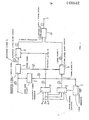
- FIG. 1 shows a block diagram of a video signal superimposing device according to an embodiment of the present invention.
- a color complex video signal produced by each of a television, a video recorder, a video disc, or the like is inputted into a video signal input terminal 1.
- the color complex video signal is applied to a burst gate circuit 2 and a brightness signal- ' chroma signal separation circuit 7.
- the burst gate circuit 2 separates a burst signal component from the inputted color complex video signal.
- the burst signal is applied to a color subcarrier generator 3, and the color subcarrier generator 3 generates a color subcarrier signal of 3.58 MHz based on the burst signal separated by the burst gate circuit 2.
- the color subcarrier signal of 3.58 MHz is applied to a chroma signal generator 6.
- R.G.B. signals Read, Green, Blue signals
- R.G.B. signals such as signals for data formed by a personal computer, or the like are inputted into R.G.B. signal input terminals 4a, 4b, and 4c, respectively.
- the R.G.B. signals inputted into the R.G.B. signal input terminals 4a, 4b, and 4c are applied to a brightness signal generator 5 and the chroma signal generator 6.
- the brightness signal generator 5 outputs a brightness signal Y2 based on the R.G.B. signals, and the brightness signal Y2 is applied to a brightness signal mixer circuit 8.
- the chroma signal generator 6 outputs a chroma signal C2 based on the R.G.B. signals inputted from the R.G.B. signal input terminals 4a, 4b, and 4c and the color subcarrier signal generated by the color subcarrier generator 3, and the croma signal C2 is applied to a chroma signal mixer circuit 9.
- the color complex video signal applied to the brightness signal-chroma signal separation circuit 7 is separated into a brightness signal Y 1 and-a chroma signal C1 by the brightness signal-chroma signal separation circuit 7.
- the brightness signal Y 1 outputed the brightness signal-chroma signal separation circuit 7 is applied to the brightness signal mixer circuit 8.
- the brightness signal mixer circuit 8 mixes the brightness signal Y 1 separated by the brightness signal-chroma signal separation circuit 7 and the brightness signal Y2 produced by the brightness signal generator 5, and the mixed brightness signal Y is applied to a brightness signal-chroma signal mixer circuir 10.
- the chroma signal mixer circuit 9 mixes the chroma signal Cl separated by the brightness signal-chroma signal separation circuit 7 and the chroma signal C2 genearted by the chroma signal generator 6, and the mixed chroma signal C is applied to the brightness signal-chroma signal mixer circuit 10.
- the brightness signal-chroma signal mixer circuit 10 mixes the brightness signal Y produced by the brightness signal mixer circuit 8 and the chroma signal C produced the chroma signal mixer circuit 9 so as to form a color composite video signal for superimposing and clearly displaying two video signals produced from two discrete systems on a display means .
- the output of the brightness-chroma signal mixer circuit 10 is applied to the display means -through a video signal output terminal 11, so that two video signals produced by the different systems are superimposed and clearly displayed on the display means.
- the color complex video signal is applied from a color television receiver and the R.G.B. signals are applied from the other apparatus such as the personal computer
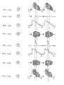
- the color complex video signal as shown in FIG. 2(A) is applied to the signal input terminal 1
- the R.G.B. signals are applied to the R.G.B. signal terminals 4a, 4b, and 4c, respectively.
- the color complex video signal is inputted into the burst gate circuit 2 and the brightness signal-chroma signal separation circuit 7.
- the burst gate circuit 2 separates and outputs the burst signal component as shown in FIG. 2(B) from the color composite video signal so as to introduce it into the color subcarrier generator 3.
- the brightness signal-chroma signal separation circuit 7 separates and outputs the brightness signal Y 1 as shown in FIG. 2(C) and the chroma signal C1 as shown in FIG. 2(D).
- the brightness signal Y1 outputted from the brightness signal-chroma signal separation circuit 7 is introduced into the brightness mixer circuit 8.
- the chroma signal Cl outputted from the brightness-chroma signal separation circuit 7 is introduced into the chroma signal mixer circuit 9.
- the color subcarrier genarator 3 generates continuously the color subcarrier signal of 3.58 MHz based on the burst signal inputted lrom the burst gate circuit 2.
- the color subcarrier signal of 3.58 MHz corresponds with a frequency and a phase of the burst signal from the burst gate circuit 2.
- the color subcarrier signal is applied to the chroma signal generator 6.
- the chroma signal C2 as shown in FIG. 2(F) is formed by the chroma signal generator 6 based on the R.G.B. signals applied via the R.G.B. signal input terminals 4a, 4b, 4c, and is applied to the chroma signal mixer circuit 9.
- the brightness signal-chroma signal mixer circuit 8 mixes two type brightness signals Y1 and Y2 applied from the brighness signal-chroma signal separation circuit 7 and the brightness signal generator 5, so that the mixed or composite brightness signal Y as shown in FIG. 2(G) produced by the brightness signal mixer circuit 8 is outputted into the brightness signal-chroma signal mixer circuit 10.
- the chroma signal mixer circuit 9 mixes two type chroma signals Cl and C2 outputted from the brightness signal-chroma signal separation circuit 7 and the chroma signal genarator 6, so that the mixed or composite chroma signal C is produced as shown in FIG. 2(H) and is applied to the brightness-chroma signal mixer circuit 10, also.
- the composite brightness signal Y and the composite chroma signal C are mixed by the brightness signal-chroma signal mixer circuit 10, and a single color composite video signal as shown in FIG. 2(I) for superimposing and clearly displaying one video signal on the other video signal is produced by the brightness-chroma signal mixer circuit 10, and the single color composite video signal is applied to the display means via the output terminal 11.
- the color complex video signal applied to the input terminal 1 is separated into the brightness signal component and the chroma signal component.
- the brightness signal component and the chroma signal component are mixed with the brightness signal and the chroma signal applied from the other system, respectively, and thereafter, the composite brightness signal and the composite chroma signal are further mixed so as to eventually output a single color composite video signal superimposing and clearly displaying two discrete system video signals.
- the composite brightness signal and the composite chroma signal are further mixed so as to form the single color composite video signal for superimposing and clearly displaying the two type video signals, so that the brightness signal and the chroma signal rarely interfere mutually as compared with the conventional interfearace between the brightness signal and the chroma signal when two system color complex video signals are directly mixed. Accordingly, when the video signals produced from the two discrete systems are superimpopsed and displayed on the screen of the display means by using the single composite video signal outputted from the video signal superimposing device of the present invention, it does no happen that colors are crossed and mixed.
- FIG. 3 shows a circuit diagram of a video signal superimposing device according to another embodiemnt of the present invention.
- a demodulation circuit 12 is provided for demodulating the croma signal Cl separated by the brightness signal-chroma signal separation circuit 7 based on the color subcarrier signal produced from tne color subcarrier generator 3 so as to produce R.G.B. signals.
- a R.G.B. signal mixer circuit 13 mixes individually the R.G.B. signals produced by the demodulation circuit 12 and the R.G.B. signals introduced via the input terminals 4a, 4b, and 4c, respectively.
- a chroma signal generator 14 forms the croma signal C based on the mixed R.G.B. signals produced by the R.G.B. signal mixer circuit 13 and the color subcarrier signal generating from the color subcarrir signal generator 3.
- the color complex video signal is applied to the input terminal 1 from the color television receiver and the R.G.B. signals are applied to the R.G.B. signal input terminals 4a, 4b, 4c from the other apparatus such as the personal computer
- the color complex video signals as shown in FIG. 4(A) is applied to the signal input terminal 1
- the R.G.B. signals are applied to the R.G.B. signal terminals 4a, 4b, and 4c, respectively.
- the color complex video signal is inputted into the burst gate circuit 2 and the brightness signal-chroma separation circuit 7.
- the burst gate circuit 2 separates and outputs the burst signal as shown in FIG. 4(B) so as to introduce it into the color subcarrier generator 3.
- the brightness signal-chroma signal separation circuit 7 separates and outputs the brightness signal YI as shown in FIG. 4(C) and the chroma signal Cl as shown inFIG. 4(D).
- the brightness. signal Yl outputted from the brightness-chroma signal separation circuit 7 is introduced into the brightness mixer circuit 8.
- the chroma signal Cl outputted from the brightness-chroma signal separation circuit 7 is introduced into the demodulation circuit 12.
- the brightness signal Y2 is inputted into the brightness mixer circuit 8.
- the brightness signal mixer circuit 8 mixes two type brightness signals Y and Y2 produced from the brightness signal-chroma signal separation circuit 7 and the brightness generator 5 so as to form a composite brightness signal Y as shown in FIG. 4(F).
- the color subcarrier generator 3 generates continuously the color subcarrier signal of 3.58 MHz in response to the burst signal inputted from the burst gate circuit 2.
- the color subcarrier signal of 3.58 MHz corresponds with a frequency and a phase of the burst signal from the burst gate circuit 2.
- the color subcarrier signal is applied to the demodulation circuit 12 and the chroma signal generator 14.
- the demodulation circuit 12 demodulates the chroma signal separated by the brightness signal-chroma signal separation circuit 7 based on the color subcarrier signal produced from the color subcarrier generator 3 so as to produce the R.G.B. signals.
- the R.G.B. signals produced by the demodulation circuit 12 are applied to the R.G.B. signal mixer circuit 13.
- the R.G.B. signal mixer circuit 13 mixes the R.G.B. signals inputted from -the demodulation circuit 12 and the R.G.B. signals inputted from the R.G.B. signal input terminals 4a, 4b, and 4c, respectively.
- the chroma signal generator 14 produces the chroma signal C as shown in FIG. 4(G) based on the color subcarrier signal and the addition-composite R.G.B. signals, and the chroma signal C is introduced into the brightness-chroma mixer circuit 10, and the brightness signal-chroma signal mixer circuit 10 mixes the brightness signal Y produced from the brightness signal mixer circuit 8 and the chroma signal C produced from the chroma signal generator 14, so that a single color composite video signal as shown in FIG. 3(H) for superimposing and clearly displaying one video signal on the other video signal on the screen of the display means is generated and introduced into the video output terminal 11.
- the color complex signal applied to the input terminal 1 is separated into the brightness signal component and the chroma signal component, and the chroma signal is demodulated by the demodulation circuit so as to produce the R.G.B. signals.
- the brightness signal component and the R.G.B. signals are mixed with the brightness signal component and the R.G.B. signals applied from the other system, respectively, and thereafter, the addition-composite R.G.B. signals are mixed and transformed into the chroma signal, and the brightness signal and the chroma signal are further mixed so as to produce a single color composite video signal for superimposing and clearly displaying one video signal on the other video signal.
- the color composite video signal for superimposing two video signals is applied to the display means through the output terminal 11.
- the video signal superimposing device of another embodiemnt of the present invention after the color complex video signal is separated into the brightness signal component and the chroma signal component, and the chroma signal component is demodulated so as to produce the R.G.B. signals.
- the brightness signal and the R.G.B. signals are mixed with the brightness signal and the R.G.B. signals from the other system, respectively, and the mixed R.G.B. signals are transformed into the chroma signal, and thereafter, the brightness signal and the chroma signal are further mixed, so that the single color composite video signal for superimposing and clearly displaying the video signals from the two different systems is produced.
- the color complex video signal inputted into the terminal 1 may be produced by a television, a video recorder, a video disc, a laser disc, or the like.
- the R.G.B. signals inputted into the R.G.B. signal input terminals may be produced by a personal computer, or the like.
- the video signal superimposing device may be included into a personal computer, a video imaging device such as a television, a video recorder, a video disc, or the like, and the video signal superimposing device may be provided separately.
- the number of systems producing the video signals should be limited to two as described above.
Landscapes
- Engineering & Computer Science (AREA)
- Multimedia (AREA)
- Signal Processing (AREA)
- Processing Of Color Television Signals (AREA)
- Studio Circuits (AREA)
- Color Television Systems (AREA)
Applications Claiming Priority (2)
| Application Number | Priority Date | Filing Date | Title |
|---|---|---|---|
| JP58185755A JPS6076881A (ja) | 1983-10-03 | 1983-10-03 | ス−パ−インポ−ズ装置 |
| JP185755/83 | 1983-10-03 |
Publications (4)
| Publication Number | Publication Date |
|---|---|
| EP0138482A2 true EP0138482A2 (de) | 1985-04-24 |
| EP0138482A3 EP0138482A3 (en) | 1986-11-20 |
| EP0138482B1 EP0138482B1 (de) | 1991-06-05 |
| EP0138482B2 EP0138482B2 (de) | 1996-08-28 |
Family
ID=16176295
Family Applications (1)
| Application Number | Title | Priority Date | Filing Date |
|---|---|---|---|
| EP84306647A Expired - Lifetime EP0138482B2 (de) | 1983-10-03 | 1984-09-28 | Anordnung zur Überlagerung von Videosignalen |
Country Status (9)
| Country | Link |
|---|---|
| US (1) | US4639768A (de) |
| EP (1) | EP0138482B2 (de) |
| JP (1) | JPS6076881A (de) |
| KR (1) | KR890001906B1 (de) |
| AU (1) | AU556336B2 (de) |
| BR (1) | BR8405003A (de) |
| CA (1) | CA1211201A (de) |
| DE (1) | DE3484671D1 (de) |
| ES (1) | ES8606770A1 (de) |
Cited By (2)
| Publication number | Priority date | Publication date | Assignee | Title |
|---|---|---|---|---|
| US5177612A (en) * | 1990-11-13 | 1993-01-05 | Pioneer Electronic Corporation | Signal switching output device |
| WO2006052683A1 (en) | 2004-11-03 | 2006-05-18 | Honeywell International Inc. | System and method for gate access control |
Families Citing this family (20)
| Publication number | Priority date | Publication date | Assignee | Title |
|---|---|---|---|---|
| KR910000365B1 (ko) * | 1984-10-05 | 1991-01-24 | 가부시기가이샤 히다찌세이사꾸쇼 | 기억회로 |
| USRE33922E (en) * | 1984-10-05 | 1992-05-12 | Hitachi, Ltd. | Memory circuit for graphic images |
| US5450342A (en) * | 1984-10-05 | 1995-09-12 | Hitachi, Ltd. | Memory device |
| US5175838A (en) * | 1984-10-05 | 1992-12-29 | Hitachi, Ltd. | Memory circuit formed on integrated circuit device and having programmable function |
| US5448519A (en) * | 1984-10-05 | 1995-09-05 | Hitachi, Ltd. | Memory device |
| US5923591A (en) * | 1985-09-24 | 1999-07-13 | Hitachi, Ltd. | Memory circuit |
| US6028795A (en) * | 1985-09-24 | 2000-02-22 | Hitachi, Ltd. | One chip semiconductor integrated circuit device having two modes of data write operation and bits setting operation |
| US4818979A (en) * | 1986-02-28 | 1989-04-04 | Prime Computer, Inc. | LUT output for graphics display |
| JP2680348B2 (ja) * | 1988-06-01 | 1997-11-19 | 株式会社東芝 | 磁気記録装置及び再生装置 |
| US5258750A (en) * | 1989-09-21 | 1993-11-02 | New Media Graphics Corporation | Color synchronizer and windowing system for use in a video/graphics system |
| US5325449A (en) * | 1992-05-15 | 1994-06-28 | David Sarnoff Research Center, Inc. | Method for fusing images and apparatus therefor |
| US5808691A (en) * | 1995-12-12 | 1998-09-15 | Cirrus Logic, Inc. | Digital carrier synthesis synchronized to a reference signal that is asynchronous with respect to a digital sampling clock |
| US6084590A (en) * | 1997-04-07 | 2000-07-04 | Synapix, Inc. | Media production with correlation of image stream and abstract objects in a three-dimensional virtual stage |
| US6160907A (en) * | 1997-04-07 | 2000-12-12 | Synapix, Inc. | Iterative three-dimensional process for creating finished media content |
| US6124864A (en) * | 1997-04-07 | 2000-09-26 | Synapix, Inc. | Adaptive modeling and segmentation of visual image streams |
| ES2125199B1 (es) * | 1997-05-19 | 1999-09-16 | Univ Murcia | Multiplexor de video de dos canales. |
| US6266053B1 (en) | 1998-04-03 | 2001-07-24 | Synapix, Inc. | Time inheritance scene graph for representation of media content |
| US6297825B1 (en) | 1998-04-06 | 2001-10-02 | Synapix, Inc. | Temporal smoothing of scene analysis data for image sequence generation |
| US6249285B1 (en) | 1998-04-06 | 2001-06-19 | Synapix, Inc. | Computer assisted mark-up and parameterization for scene analysis |
| KR20020095883A (ko) * | 2001-06-18 | 2002-12-28 | 김정옥 | 텔레비전의 색상 표현 장치 |
Family Cites Families (8)
| Publication number | Priority date | Publication date | Assignee | Title |
|---|---|---|---|---|
| US3296367A (en) * | 1962-11-16 | 1967-01-03 | Cft Comp Fse Television | Systems for the generation of special effects in colour television |
| BE639965A (de) * | 1962-11-16 | |||
| DE1762543A1 (de) * | 1967-01-04 | 1970-08-13 | Fernseh Gmbh | Verfahren zur UEberblendung zwischen zwei Fernsehsignalen |
| US4161748A (en) * | 1977-12-22 | 1979-07-17 | Robert Bosch Gmbh | Mixing of SECAM color-T.V. signals |
| US4183045A (en) * | 1978-08-30 | 1980-01-08 | Rca Corporation | Chroma keying selector system |
| US4374395A (en) * | 1980-12-24 | 1983-02-15 | Texas Instruments Incorporated | Video system with picture information and logic signal multiplexing |
| US4425581A (en) * | 1981-04-17 | 1984-01-10 | Corporation For Public Broadcasting | System for overlaying a computer generated video signal on an NTSC video signal |
| GB2132846A (en) * | 1982-12-22 | 1984-07-11 | Philips Electronic Associated | Television transmission system |
-
1983
- 1983-10-03 JP JP58185755A patent/JPS6076881A/ja active Granted
-
1984
- 1984-09-25 CA CA000463969A patent/CA1211201A/en not_active Expired
- 1984-09-28 EP EP84306647A patent/EP0138482B2/de not_active Expired - Lifetime
- 1984-09-28 AU AU33690/84A patent/AU556336B2/en not_active Expired
- 1984-09-28 DE DE8484306647T patent/DE3484671D1/de not_active Expired - Lifetime
- 1984-10-01 US US06/656,757 patent/US4639768A/en not_active Expired - Lifetime
- 1984-10-02 KR KR1019840006090A patent/KR890001906B1/ko not_active Expired
- 1984-10-02 BR BR8405003A patent/BR8405003A/pt not_active IP Right Cessation
- 1984-10-03 ES ES536487A patent/ES8606770A1/es not_active Expired
Cited By (2)
| Publication number | Priority date | Publication date | Assignee | Title |
|---|---|---|---|---|
| US5177612A (en) * | 1990-11-13 | 1993-01-05 | Pioneer Electronic Corporation | Signal switching output device |
| WO2006052683A1 (en) | 2004-11-03 | 2006-05-18 | Honeywell International Inc. | System and method for gate access control |
Also Published As
| Publication number | Publication date |
|---|---|
| EP0138482A3 (en) | 1986-11-20 |
| EP0138482B2 (de) | 1996-08-28 |
| ES536487A0 (es) | 1986-04-01 |
| DE3484671D1 (de) | 1991-07-11 |
| ES8606770A1 (es) | 1986-04-01 |
| US4639768A (en) | 1987-01-27 |
| CA1211201A (en) | 1986-09-09 |
| BR8405003A (pt) | 1985-08-20 |
| KR850003485A (ko) | 1985-06-17 |
| EP0138482B1 (de) | 1991-06-05 |
| AU556336B2 (en) | 1986-10-30 |
| JPS6076881A (ja) | 1985-05-01 |
| JPH038633B2 (de) | 1991-02-06 |
| KR890001906B1 (ko) | 1989-05-30 |
| AU3369084A (en) | 1985-04-18 |
Similar Documents
| Publication | Publication Date | Title |
|---|---|---|
| EP0138482A2 (de) | Anordnung zur Überlagerung von Videosignalen | |
| US4442428A (en) | Composite video color signal generation from digital color signals | |
| US4500908A (en) | Method and apparatus for standardizing nonstandard video signals | |
| EP0329382B1 (de) | Schaltung zur Trennung des Helligkeitssignals von einem Farbsignal | |
| US5570200A (en) | Video disk player comprising a signal circuit for selecting one of a video data signal and a luminance signal as an out signal | |
| US6476872B1 (en) | Scanning line converting apparatus | |
| JP2502694B2 (ja) | 映像信号合成装置 | |
| KR910013891A (ko) | 텔레비젼 시스템의 보조 영상 정보 엔코딩 및 디코딩 장치 | |
| CA2203735A1 (en) | Up-converter and scanning line conversion method | |
| GB2134743A (en) | Color display system | |
| US5181099A (en) | Composite video signal generator | |
| JPS6046689A (ja) | 信号重畳装置 | |
| KR0175039B1 (ko) | 영상 신호의 지터 제거 장치 | |
| JPS5958472A (ja) | 映像表示装置 | |
| JPH04317281A (ja) | 映像機器 | |
| US5235411A (en) | Signal processing apparatus with improved alignment switching between color difference signals | |
| JP2910884B2 (ja) | 2画面表示機能を備えた映像機器 | |
| JPH0463598B2 (de) | ||
| Kohiyama et al. | Development of a digital TV system for use in computer systems | |
| JPH01237688A (ja) | パーソナルコンピュータのインターフェイス回路 | |
| JPS612192A (ja) | パソコンのビデオ回路 | |
| JP2000165773A (ja) | 映像信号合成装置 | |
| JPS6075871A (ja) | データ表示システム | |
| JPH0525889U (ja) | ビデオ入出力装置 | |
| JPS6226985A (ja) | テレビジヨン受信機 |
Legal Events
| Date | Code | Title | Description |
|---|---|---|---|
| PUAI | Public reference made under article 153(3) epc to a published international application that has entered the european phase |
Free format text: ORIGINAL CODE: 0009012 |
|
| AK | Designated contracting states |
Designated state(s): DE FR GB |
|
| PUAL | Search report despatched |
Free format text: ORIGINAL CODE: 0009013 |
|
| AK | Designated contracting states |
Kind code of ref document: A3 Designated state(s): DE FR GB |
|
| 17P | Request for examination filed |
Effective date: 19870321 |
|
| 17Q | First examination report despatched |
Effective date: 19890407 |
|
| GRAA | (expected) grant |
Free format text: ORIGINAL CODE: 0009210 |
|
| AK | Designated contracting states |
Kind code of ref document: B1 Designated state(s): DE FR GB |
|
| REF | Corresponds to: |
Ref document number: 3484671 Country of ref document: DE Date of ref document: 19910711 |
|
| ET | Fr: translation filed | ||
| PLBI | Opposition filed |
Free format text: ORIGINAL CODE: 0009260 |
|
| 26 | Opposition filed |
Opponent name: GRUNDIG E.M.V. ELEKTRO-MECHANISCHE VERSUCHSANSTALT Effective date: 19920226 |
|
| PLAW | Interlocutory decision in opposition |
Free format text: ORIGINAL CODE: EPIDOS IDOP |
|
| PUAH | Patent maintained in amended form |
Free format text: ORIGINAL CODE: 0009272 |
|
| STAA | Information on the status of an ep patent application or granted ep patent |
Free format text: STATUS: PATENT MAINTAINED AS AMENDED |
|
| 27A | Patent maintained in amended form |
Effective date: 19960828 |
|
| AK | Designated contracting states |
Kind code of ref document: B2 Designated state(s): DE FR GB |
|
| ET3 | Fr: translation filed ** decision concerning opposition | ||
| APAC | Appeal dossier modified |
Free format text: ORIGINAL CODE: EPIDOS NOAPO |
|
| APAC | Appeal dossier modified |
Free format text: ORIGINAL CODE: EPIDOS NOAPO |
|
| REG | Reference to a national code |
Ref country code: GB Ref legal event code: IF02 |
|
| PGFP | Annual fee paid to national office [announced via postgrant information from national office to epo] |
Ref country code: FR Payment date: 20030909 Year of fee payment: 20 |
|
| PGFP | Annual fee paid to national office [announced via postgrant information from national office to epo] |
Ref country code: GB Payment date: 20030924 Year of fee payment: 20 |
|
| PGFP | Annual fee paid to national office [announced via postgrant information from national office to epo] |
Ref country code: DE Payment date: 20031009 Year of fee payment: 20 |
|
| PG25 | Lapsed in a contracting state [announced via postgrant information from national office to epo] |
Ref country code: GB Free format text: LAPSE BECAUSE OF EXPIRATION OF PROTECTION Effective date: 20040927 |
|
| REG | Reference to a national code |
Ref country code: GB Ref legal event code: PE20 |
|
| APAH | Appeal reference modified |
Free format text: ORIGINAL CODE: EPIDOSCREFNO |