EP0134603A2 - Agricultural implement linkage - Google Patents
Agricultural implement linkage Download PDFInfo
- Publication number
- EP0134603A2 EP0134603A2 EP84201061A EP84201061A EP0134603A2 EP 0134603 A2 EP0134603 A2 EP 0134603A2 EP 84201061 A EP84201061 A EP 84201061A EP 84201061 A EP84201061 A EP 84201061A EP 0134603 A2 EP0134603 A2 EP 0134603A2
- Authority
- EP
- European Patent Office
- Prior art keywords
- frame
- implement
- lifting
- trestle
- fastening members
- Prior art date
- Legal status (The legal status is an assumption and is not a legal conclusion. Google has not performed a legal analysis and makes no representation as to the accuracy of the status listed.)
- Withdrawn
Links
Images

Classifications
-
- A—HUMAN NECESSITIES
- A01—AGRICULTURE; FORESTRY; ANIMAL HUSBANDRY; HUNTING; TRAPPING; FISHING
- A01B—SOIL WORKING IN AGRICULTURE OR FORESTRY; PARTS, DETAILS, OR ACCESSORIES OF AGRICULTURAL MACHINES OR IMPLEMENTS, IN GENERAL
- A01B63/00—Lifting or adjusting devices or arrangements for agricultural machines or implements
- A01B63/02—Lifting or adjusting devices or arrangements for agricultural machines or implements for implements mounted on tractors
- A01B63/10—Lifting or adjusting devices or arrangements for agricultural machines or implements for implements mounted on tractors operated by hydraulic or pneumatic means
- A01B63/102—Lifting or adjusting devices or arrangements for agricultural machines or implements for implements mounted on tractors operated by hydraulic or pneumatic means characterised by the location of the mounting on the tractor, e.g. on the rear part
-
- A—HUMAN NECESSITIES
- A01—AGRICULTURE; FORESTRY; ANIMAL HUSBANDRY; HUNTING; TRAPPING; FISHING
- A01B—SOIL WORKING IN AGRICULTURE OR FORESTRY; PARTS, DETAILS, OR ACCESSORIES OF AGRICULTURAL MACHINES OR IMPLEMENTS, IN GENERAL
- A01B59/00—Devices specially adapted for connection between animals or tractors and agricultural machines or implements
- A01B59/06—Devices specially adapted for connection between animals or tractors and agricultural machines or implements for machines mounted on tractors
- A01B59/066—Devices specially adapted for connection between animals or tractors and agricultural machines or implements for machines mounted on tractors of the type comprising at least two lower arms and one upper arm generally arranged in a triangle, e.g. three-point hitches
- A01B59/067—Devices specially adapted for connection between animals or tractors and agricultural machines or implements for machines mounted on tractors of the type comprising at least two lower arms and one upper arm generally arranged in a triangle, e.g. three-point hitches the lower arms being lifted or lowered by power actuator means internally incorporated in the tractor
-
- A—HUMAN NECESSITIES
- A01—AGRICULTURE; FORESTRY; ANIMAL HUSBANDRY; HUNTING; TRAPPING; FISHING
- A01C—PLANTING; SOWING; FERTILISING
- A01C15/00—Fertiliser distributors
- A01C15/005—Undercarriages, tanks, hoppers, stirrers specially adapted for seeders or fertiliser distributors
-
- A—HUMAN NECESSITIES
- A01—AGRICULTURE; FORESTRY; ANIMAL HUSBANDRY; HUNTING; TRAPPING; FISHING
- A01C—PLANTING; SOWING; FERTILISING
- A01C17/00—Fertilisers or seeders with centrifugal wheels
Definitions
- An implement which comprises a frame provided with lower fastening members for coupling the implement with a lifting arm of a lifting device of a vehicle, the frame being connected at or near the fastening members to an upwardly extending lifting trestle which is provided with fastening members for coupling the trestle to the lifting arms for supporting the implement in an elevated position.
Landscapes
- Life Sciences & Earth Sciences (AREA)
- Soil Sciences (AREA)
- Environmental Sciences (AREA)
- Engineering & Computer Science (AREA)
- Mechanical Engineering (AREA)
- Zoology (AREA)
- Fertilizing (AREA)
- Agricultural Machines (AREA)
- Soil Working Implements (AREA)
Abstract
Description
- This invention relates to an agricultural implement, and particularly, although not exclusively, to an implement in the form of a spreader for spreading distributable material such as fertilizer.
- An implement is known which comprises a frame provided with lower fastening members for coupling the implement with a lifting arm of a lifting device of a vehicle, the frame being connected at or near the fastening members to an upwardly extending lifting trestle which is provided with fastening members for coupling the trestle to the lifting arms for supporting the implement in an elevated position.
- With implements of this kind, the lifting trestle is used to enable the implement to be used at a higher than usual level. For example, where the implement is a spreader for spreading material such as fertilizer, the lifting trestle is used when spreading fertilizer above standing crop which has already grown to an appreciable height.
- According to the present invention, the lifting trestle is movable relatively to the frame and fixable selectively in any one of at least two different positions, whereby the fastening members of the frame are displaceable between two positions which are spaced apart in the direction of the normal intended direction of operative travel of the implement.
- Thus, when fastening the implement to the tractor or a similar vehicle using the lifting trestle, it can be positioned with respect to the tractor in either of these two spaced positions. In this way the implement can be brought into an optimum position with respect to the tractor. The implement can be mounted with respect to the tractor in a manner such that its centre of gravity is as near as possible to the tractor. Alternatively, the implement can be mounted so that, even in the elevated position of the implement, it cannot undesirably come into contact with parts of the tractor, which might cause damage to the implement or the tractor. Moreover, the implement can be moved into an optimum position with respect to other machinery with which the implement has to co-operate when two or more machines are coupled to the same tractor or similar vehicle.
- An advantageous embodiment of the implement is obtained when the vertical distance between the fastening members of the lifting trestle and the fastening points between the lifting trestle and the frame is not less than about 0.7 times and not more than about 1.5 times the distance between the lower fastening members and upper fastening members of the frame. The upper fastening member of the frame may be adapted for attachment to the top rod of the three-point lifting device of a tractor.
- The lifting trestle may be pivotally coupled with the frame. The displacement of the lifting trestle with respect to the frame can be advantageously performed when the lifting trestle is connected by means of at least one strut to the rear of the frame, the strut preferably being adjustable in length.
- At least one of the lower fastening members of the frame may be adjustable upwardly and downwardly with respect to the frame and fixable selectively in one of at least two different positions relatively to the frame. In this way the spreader may be tilted with respect to the ground. This can be useful particularly where the implement is a spreader comprising distribution members which are rotatable about upwardly extending axes, for setting the distribution members in an inclined position relative to the surface to be covered. Thus the distribution pattern of the material in some circumstances can be varied.
- The adjustable fastening member of the frame may be pivotally connected with the rest of the frame for movement about a pivotal axis which extends substantially horizontally and substantially transversely of the normal intended direction of operative travel of the implement.
- For a better understanding of the present invention and to show how it may be carried into effect, reference will now be made, by way of example, to the accompanying drawings, in which:
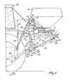
- Figure 1 is a side view of a spreader mounted on a tractor;
- Figure 2 is a front view of the spreader taken in the direction of the arrow II in Figure 1;
- Figure 3 shows the spreader of Figure 1 in a different position;
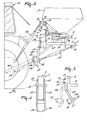
- Figure 4 shows an alternative construction for part of the spreader;
- Figure 5 shows another alternative construction for the part shown in Figure 4;
- Figure 6 is a side view of part of the spreader similar to that of Figures 1 to 3, but showing a modification;
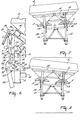
- Figure 7 is a front view of a spreader having the modifications shown in Figure 6; and
- Figure 8 shows the spreader of Figure 7 in a different position.
- The spreaders illustrated in the drawings are intended for agricultural use for spreading distributable material such as fertilizer.
- The spreader comprises a
frame 1 provided with ahopper 2 and distribution members 3 and 4 disposed below the hopper. The distribution members 3 and 4 are coupled with drive gear 5 (not shown in detail) which includes aninput shaft 6. The spreader also has a dosing arrangement 7 (not shown in detail) which comprises ports (not shown) in the hopper opening out above the distribution members 3 and 4. - At the front, the
frame 1 has two mutually parallel, upwardly extending ports 8 and 9, the top ends of which are interconnected by a horizontal frame beam 10, to which the hopper is fastened. The front ends of a V-shaped horizontal lower beam 11 are fastened to the posts 8 and 9 near their lower ends. The limbs of the beam 11 converge from the beams 8 and 9 towards the rear and meet each other. - Slightly above the lower end of the post 8 there is a fastening member 12 which is in the form of two plates arranged one on each side of the post 8. The port 9 is provided in the same manner with a
similar fastening member 13. Thefastening members 12 and 13 are secured at the same height to theframe 1 and have alignedholes fastening member 16 comprising two strips mounted a short distance apart and having aligned holes 17. The spreader is provided with alifting trestle 20 connected to theframe 1. Thelifting trestle 20 comprises two upwardly extending supportingbeams intermediate beam 23, situated near the lower ends of thebeams beams members plates beam plates 26 are on the outboard sides of thebeams plates 27 are on the inboard sides of thebeams plates beams plates 27 also project, as is shown in Figure 1, to the rear of thebeams tongues 28. The supportingbeans members 12 and 13 bypivotal shafts lifting trestle 20 is coupled bystruts frame 1. Each of thestruts sleeve 25 androds 33 and 34 constituting a turnbuckle. Therods 33 and 34 have opposite screwthreads and thesleeve 25 has corresponding internal screwthreads. Thestruts tongues 28. therods 33 and 34 are provided withtongues 38, which are pivotally coupled bypivot pins 39 to a plate 40 fastened to the horizontal beam 11. The lengths of thestruts tongues sleeves 35 with respect to thescrewthreaded rods 33 and 34, which thus penetrate into thesleeve 35 to a greater or lesser extent. - In use of the spreader, it is coupled with the lifting device of a
tractor 45 by connecting ends of liftingarms 44 of the lifting device between theplates fastening members fastening member 16 is then coupled with atop rod 46 of the lifting device. An auxiliary shaft 47 connects theinput shaft 6 to the power take-off shaft of the tractor. - The spreader shown is used to spread distributable material, in particular granular and/or powdery material, for example fertilizer. During travel of the spreader across the surface to be covered, for example a field to be fertilized, the material is carried in the
hopper 2 and is fed at a desired rate from the hopper through the dosing members 7 (not shown in detail) to the distribution members 3 and 4. The distribution members 3 and 4 are rotated during operation from the power take-off shaft 48 of the tractor through theauxiliary shaft 46 and theinput shaft 6. The drive train is such that the distribution members 3 and 4 rotate in opposite senses about their upwardly extending rotary axes, the proximal sides of the distribution members moving in the intended direction 52 of operative travel of the spreader. The construction of the distribution members 3 and 4, their directions of rotation and the positions of the outlet ports of the hopper are chosen so that during operation of the spreader the two distribution members 3 and 4 spread the material symmetrically with respect to the centralvertical plane 63. Theplane 63 contains the longitudinal centreline of the spreader, the spreader being substantially symmetrical about theplane 63. Each of the distribution members spreads the material mainly to the rear over a width extending practically equally to both sides of the spreader. Thus the material is spread by each of the distribution members 3 and 4 over substantially the whole working width of the spreader so that the spreading sectors of the two distribution members overlap each other practically completely. The spreader is particularly suitable for spreading, for example, fertilizer on standing crop of considerable height. The distribution members 3 and 4 can be held by the lifting trestle, for example, at a distance of 1.50 ms above the ground. The material can thus be spread on standing crop at least one metre high. - The lifting
trestle 20 is pivotable with respect to theframe 1 about a horizontal axis extending normal to the direction 52 and embodied by the aligned pins 29 and 30, by which the trestle is secured to thefastening members 12 and 13. The pivotal movement of the trestle with respect to theframe 1 can be effected by adjusting the length of thestruts sleeve 35 with respect to thescrew spindles 33 and 34. By lengthening thestruts trestle 20 can turn with respect to theframe 1 about thepins frame 1 and can take up a position as shown, by way of example, in Figure 3. If the position of the liftingarms 44 is maintained, the spreader will move to the rear with respect to thepins 49 by which thefastening arms arms 44. The supporting beams 21 and 22, which, in Figure 1, slope to the rear from top to bottom at an angle 50 of about 10° to the vertical posts 8 and 9, which themselves are perpendicular to the distribution members 3 and 4 parallel to the rotary axes of the distribution members 3 and 4, move to a position in which, as shown in Figure 3, they slope to the front from top to bottom, at an angle 51 of about 10° to the posts 8 and 9. The liftingtrestle 22 has then turned through 20° about theshafts frame 1. It will be obvious that the angular position of the liftingtrestle 22 with respect to theframe 1 can be fixed selectively in any one of a plurality of positions by lengthening or shortening thestruts trestle 20 with respect to theframe 1 about the pivotal axis formed by thepins frame 1 and the distribution members 3 and 4 can thus be displaced in a direction parallel to the direction 52 with respect to the tractor to a greater or lesser extent. Thus the spreader can be optionally positioned closer to or further from the tractor. By moving the spreader with respect to thetractor 45 in the direction 52, the centre of gravity of the spreader is also displaced in that direction with respect to the tractor. Thus, for example, when the spreader is held in a high position by the lifting trestle and when the tractor is relatively small, it may be advantageous for the spreader to be as near to the tractor as possible. To this end the lifting trestle can be turned to the rear as far as possible with respect to theframe 1. The angle 50 is then set at its maximum value. - In other circumstances, it may be important for the spreader to be displaced with respect to the tractor in the direction 52 in order to avoid the spreader coming into undesirable contact with parts of the tractor, which might damage the spreader and/or the tractor. Because of the relatively great length of the
trestle 20 between thepins pins 49 on the other, displacement of the spreader with respect to the tractor in the direction 52 can be carried out without any significant change in the height of the spreader and hence of the distribution members 3 and 4 above the ground. Thevertical distance 53 between thepins pins 49 is in the illustrated embodiment slightly larger than thedistance 54 between theholes 15 and the holes 17 of thefastening members distance 53 is not less than 0.7 times thedistance 54 and not more than about 1.5 times thedistance 54. - It will be clear that the height of the spreader with the distribution members 3 and 4 above the ground can also be varied by moving the lifting
arms 44 upwardly or downwardly. The liftingtrestle 20, therefore, serves to support the spreader at a considerable height above the ground and to displace the spreader parallel to the direction 52 by turning the trestle with respect to theframe 1. In order to maintain the horizontal position of the distribution members 3 and 4, i.e. to keep them parallel to the ground, the length of thetop rod 46 can be adjusted. The length of thestruts trestle 20 can turn through an angle of at least 10° to either side of the vertical about the pivotal axis formed by the pins 29-and 30. During this movement the height of the distribution members 3 and 4 above the ground will hardly change owing to the relativelygreat length 53, whilst nevertheless a significant fore-and-aft displacement of the spreader can be achieved. - It will be clear that the permissible range of movement of the
trestle 20 of theframe 1 may be other than 10° in each direction, as given above for the angles 50 and 51. In order to enable a larger turn of thetrestle 20 with respect to theframe 1 to the rear than is shown in Figure 1 the top ends of thebeams plates 57 and 58 as shown in Figure 4. These plates can be fitted on the outer sides of theplates plates pivotal pins plates 57 and 58 is such that they can move past the posts 8 and 9 on both sides so that the desired angular turn of the liftingtrestle 20 may take place to the rear with respect to the frame. In an alternative shown in Figure 5, thebeams sharp bend 59 so that the trestle can turn further before thebeams frame 1, thehopper 2 and the distribution members 3 and 4 is a model of an existing spreader to which the lifting trestle has been fastened without the need for further alterations. - The spreader comprising the
frame 1, thehopper 2 and the distribution members 3 and 4 may also be used without the liftingtrestle 20. The trestle can be detached from'theframe 1 by loosening thestruts beams fastening members 12 and 13. The spreader can then be coupled with the lifting device without the lifting trestle, the liftingarms 44 then being coupled by means of thepins fastening members 12 and 13. The top rod remains coupled to thefastening members 16, but will be considerably shorter. Theinput shaft 6 would also need to be coupled to the power take-offshaft 48 by a shorter auxiliary shaft 47 so that the spreader can be used with the distribution members 3 and 4 at a much lower height above the ground. The spreader is then suitable for spreading material, for example fertilizer, on the ground with the distribution members 3 and 4 at about 60 cms above the ground. - Although the invention has been described with reference to a spreader comprising rotatable distribution members 3 and 4, the principle of the invention, i.e. the use of a lifting trestle displaceably fitted to an agricultural implement, can also be applied to agricultural devices other than the spreader shown. The lifting
trestle 20 can, in general, be used to put any agricultural implement or part thereof in a considerably higher position and to position it with respect to the tractor optionally in any one of two or more positions spaced from each other in the direction 52. - The connection of the top ends of the
beams fastening members 12 and 13 and the coupling of the liftingtrestle 20, through thestruts beams - In order to enable the distribution members 3 and 4 to be put into a desired position, for example at a particular angle to the horizontal when the lifting
trestle 20 is turned about the pivotal axis of thepins pivotal shaft 60 along ascale 62. The position of the pointer 61 with respect to thescale 62 indicates the attitude of the distribution members 3 and 4 with respect to the horizontal. The distribution members can then be adjusted simply by altering the length of thetop rod 46 after the spreader has been moved to the desired height. - Figures 6, 7 and 8 show a different construction for part of the spreader shown in Figures 1, 2 and 3, in which the
fastening member 13 of Figures 1, 2 and 3 is replaced by atilting mechanism 66. Thismechanism 66 is shown in Figure 6 in a side view corresponding to that of Figure 1. Thetilting mechanism 66 comprises afastening member 67 made up of twoplates 68 disposed one on each side of the post 9 and rigidly secured to each other by a tie strip 71. Thefastening member 67 is pivotable with respect to the post 9 about apivotal shaft 69. Theshaft 69 is mounted on the rear of the post 9 by means of supportinglugs 70. Thefastening member 67 has holes 72 corresponding to theholes 15 which enable the top end of the supportingbeam 22 of the liftingtrestle 20 to be fastened to themember 67 by means of apin 30, in a manner analogous to the connection of thebeam 22 to thefastening member 13 in the preceding embodiment . Thetilting mechanism 66 also comprises a liftingmember 73, 'which in this embodiment is a hydraulic lifting member comprising a cylinder 74 and a piston rod 75. The liftingmember 73 is pivotally fastened by means of a pivotal shaft 77 totongues 76 on the beam 10. The lower end of the rod 75 of the liftingmember 73 is pivotally connected between theplates 68 by means of apivotal shaft 78. Theplates 68 of thefastening member 67 have alignedholes holes 80 and 81 being situated at equal distances on opposite sides of thehole 79. Thehole 79 can thus be termed a middle hole, and theholes 80 and 81 can be termed lower and upper holes respectively. Apin 82 can be inserted selectively into any one of theholes stop pin 82 is shown in themiddle hole 79. Thepin 82 extends through the alignedholes 79 in the twoplates 68 on both sides of the post 9. - When using the device it is coupled with the lifting device of a tractor in the same manner as shown in Figures 1 to 5.
- The lifting trestle can be set in the desired position relative to the
frame 1 by means of thestruts beam 22 and hence the liftingtrestle 20 is in a position relative to theframe 1 corresponding to Figure 1. When the lockingpin 82 is located in themiddle hole 79, the spreader is held in a position corresponding to that shown in Figures 1 and 2, in which the distribution members 3 and 4 and the beam 10 are parallel to the ground, but the position of thefastening member 67 relative to theframe 1 can be altered as follows. By operating the liftingmember 73, thefastening member 67 can be turned about thepivotal shaft 69 with respect to theframe 1. In the position shown in Figure 6, thepin 30, the liftingtrestle 20 and the liftingarms 44 are held stationary, and the weight of the spreader is transferred through thepivotal shaft 69 to thefastening members 67. Under the weight of the spreader, thepivotal shaft 69 tends to move downwards with respect to thepin 30 so that thefastening member 67 tends to turn about theshaft 69 and thepin 30. This is prevented by thestop pin 82 inserted through themiddle hole 79 and bearing on the front of the post 9 or on a stop provided thereon. In this way the position of thefastening member 67 is established. - By subjecting the lifting
member 73, which may be connected through ducts (not shown) with the hydraulic circuit of the tractor, to a pressure such that the rod 75 is extended from the cylinder 74, thepivotal shaft 78 is moved downwardly. As a result, thefastening member 67 will turn downwards about thepivotal shaft 69 so that thepin 82 moves out of contact with the post 9 and can be removed from themiddle hole 79. Thefastening member 67 can be turned downwards about thepin 69 by the liftingmember 73 until theupper hole 81 is in front of the post 9, and thepin 82 can then be inserted into theupper hole 81. The pressure in the liftingmember 73 can then be relieved, thepin 82 in thehole 81 preventing thefastening member 67 from turning upwards about thepivotal shaft 59. Thepivotal shaft 69 and hence the spreader have thus been moved upwards with respect to thepin 30, but the fastening member 12 (Figure 2) at the top end of thebeam 21 of the trestle remains at the same height so that the spreader will occupy an inclined position as shown in Figure 7. In this position the distribution members 3 and 4 are inclined to the ground laterally of the direction 52. They are inclined downwardly to the right. This position may be used for spreading material near the edge of a field to the right over a smaller distance. The material is uniformly distributed over this smaller distance. Tilting of the distribution members is such that the distribution to the left-hand side of the spreader remains practically unchanged. The material spread to the left-hand side is overlapped at least partly during the next run so that a uniform distribution of the material is obtained over this area in the normal manner. The material spread over an edge strip of the field on the right-hand side will, however, not be overlapped by a spreading run made further to the right-hand side. It is, therefore, necessary to distribute the material uniformly over the whole width of this edge strip in a single pass. When, viewed in the direction 52, the material has to be spread on a left-hand side strip of the field to be covered, the spreader can be tilted downwards to the left as is indicated in Figure 8. In order to achieve this position, the liftingmember 73 is again pressurised by pressing fluid into the cylinder 74 so that the rod 75 is extended. Thestop pin 81 is released from its contact with the front of the post 9 and thepin 82 can be removed from thehole 81. The pressure is then relieved so that the distance between thepivotal shafts 77 and 78 is shortened by expelling fluid from the cylinder 74 under the weight of the spreader. Shortening the distance between theshafts 77 and 78 below a given value is prevented by inserting thepin 82 into the lower holes 80 of theplates 68. When the spreader moves down and thefastening member 67 turns about thepivotal shaft 69, thepin 82 inserted into the holes 80 will thus make contact with the stop formed by the post 9. Further upward turning of thefastening member 67 about thepin 69 is thus avoided. The spreader then occupies the position shown in Figure 8. The distance between theholes beams trestle 20. This pivotal movement may be permitted by the clearance between the coupling pins 29 and 30 and theholes 14 and 72. Thestruts shafts 37 and 39 in their notes. Any shortening or lengthening of thestruts shafts 37 and 39 in their holes. Any shortening or lengthening of the struts between the supportinglugs 28 and the plate 40 which might be necessitated by the tilting can be achieved by turning thesleeves 35. The arrangement shown of thestruts lugs 28 and the plate 40 is, therefore, advantageous in obtaining the desired tilting of the spreader with respect to the liftingtrestle 20, which position is particularly used for spreading fertilizer above standing crop already fairly high above the ground. - Although in the embodiment shown in Figures 6, 7 and 8 there is a
tilting mechanism 66 on only one side of the spreader for moving the spreader on one side into at least three positions determined by theholes tilting mechanism 66 of Figures 6, 7 and 8. In this case each tilting mechanism needs to have only two possible positions relative to the frame of the spreader in order to obtain the two oppositely inclined positions of Figures 7 and 8. Theplates 68 of the fastening members then need only twoholes - As stated above with respect to the preceding embodiment, the device shown in Figures 6, 7 and 8 may also be employed without the
trestle 20 on theframe 1 of the spreader. Thefastening members 12 and 67 would then be coupled to the liftingarms 44 of the lifting device, and thetop rod 46 would be coupled to thefastening member 16. Thetilting mechanism 66 could still be used to tilt the spreader to the left or to the right as shown in Figure 7 and 8. This tilting would, however, take place with the distribution members 3 and 4 at a smaller distance above the ground. - Whilst various features of the spreaders that have been described, and that are illustrated in the drawings, will be set forth in the following claims as inventive features, it is to be noted that the invention is not necessarily limited to these features and that it encompasses all of the features that have been described both individually and in various combinations.
Claims (25)
Applications Claiming Priority (2)
| Application Number | Priority Date | Filing Date | Title |
|---|---|---|---|
| NL8302688 | 1983-07-28 | ||
| NL8302688A NL8302688A (en) | 1983-07-28 | 1983-07-28 | AGRICULTURAL APPARATUS, IN PARTICULAR AN APPARATUS FOR THE SPREAD OF SPREADABLE MATERIAL. |
Publications (2)
| Publication Number | Publication Date |
|---|---|
| EP0134603A2 true EP0134603A2 (en) | 1985-03-20 |
| EP0134603A3 EP0134603A3 (en) | 1986-05-28 |
Family
ID=19842214
Family Applications (1)
| Application Number | Title | Priority Date | Filing Date |
|---|---|---|---|
| EP84201061A Withdrawn EP0134603A3 (en) | 1983-07-28 | 1984-07-16 | Agricultural implement linkage |
Country Status (5)
| Country | Link |
|---|---|
| EP (1) | EP0134603A3 (en) |
| DE (1) | DE3427575A1 (en) |
| FR (1) | FR2549684B1 (en) |
| GB (1) | GB2144021B (en) |
| NL (1) | NL8302688A (en) |
Cited By (4)
| Publication number | Priority date | Publication date | Assignee | Title |
|---|---|---|---|---|
| EP0198562A1 (en) * | 1985-04-16 | 1986-10-22 | C. van der Lely N.V. | An apparatus for spreading material |
| EP0327941A1 (en) * | 1988-02-12 | 1989-08-16 | Amazonen-Werke H. Dreyer GmbH & Co. KG | Fertilizer broadcaster |
| US20100117346A1 (en) * | 2008-11-13 | 2010-05-13 | Wolfgang Bauer | Agricultural vehicle balancing system |
| KR20230046713A (en) * | 2021-09-30 | 2023-04-06 | 김성진 | Dron for scattering agricultural solution and particle |
Families Citing this family (4)
| Publication number | Priority date | Publication date | Assignee | Title |
|---|---|---|---|---|
| DK313489A (en) * | 1989-06-23 | 1990-12-24 | Laursen As A P | APPLICATION FOR DISTRIBUTION OF ARTIFICIAL FERTILIZERS |
| FR2653294B1 (en) * | 1989-10-23 | 1992-01-10 | Noremat | HITCH COMPRISING A TRACTOR AND A TRUCK ATTACHED BEFORE IT. |
| DE4124000A1 (en) * | 1991-03-22 | 1992-09-24 | Amazonen Werke Dreyer H | SLINGER SPREADER |
| ITMI20091262A1 (en) * | 2009-07-16 | 2011-01-17 | Dragone S R L Con Unico Socio | AGRICULTURAL MACHINE FOR THE TREATMENT OF PREFERIBLY PLANTED PLANTS |
Family Cites Families (8)
| Publication number | Priority date | Publication date | Assignee | Title |
|---|---|---|---|---|
| SE7504215L (en) * | 1975-07-29 | 1976-12-10 | Avikens Metall Ab | CONTROL SYSTEM FOR LIQUID DISTRIBUTION T EX FOR GARDEN IRRIGATION |
| DE2622444C3 (en) * | 1976-05-20 | 1981-01-22 | Amazonen-Werke H. Dreyer Gmbh & Co Kg, 4507 Hasbergen | Attachment device for agricultural distribution machines |
| DE2719405B2 (en) * | 1977-04-30 | 1979-11-15 | Amazonen-Werke H. Dreyer Gmbh & Co Kg, 4507 Hasbergen | Machine for spreading fertilizers |
| IE47476B1 (en) * | 1977-11-22 | 1984-03-21 | Keenan Richard | Improved means for mounting implements on tractors |
| DE2756509B1 (en) * | 1977-12-19 | 1979-06-13 | Amazonen Werke Dreyer H | Centrifugal fertilizer spreader |
| DE2841620A1 (en) * | 1978-09-25 | 1980-04-03 | Niemeyer Gmbh & Co Kg Soehne | Centrifugal fertilizer spreaders mounting - has swing arm with two bottom connections for spreader and tractor power lift to maintain spreader horizontal |
| DE3128561A1 (en) * | 1981-07-18 | 1983-01-27 | Fa. Heinrich Wilhelm Dreyer, 4515 Bad Essen | Agricultural machine |
| NL8201807A (en) * | 1982-05-03 | 1983-12-01 | Lely Nv C Van Der | 3-POINT LINKAGE ATTACHMENT OF A TRACTOR. |
-
1983
- 1983-07-28 NL NL8302688A patent/NL8302688A/en active Search and Examination
-
1984
- 1984-07-16 EP EP84201061A patent/EP0134603A3/en not_active Withdrawn
- 1984-07-23 GB GB08418737A patent/GB2144021B/en not_active Expired
- 1984-07-23 FR FR8411648A patent/FR2549684B1/en not_active Expired
- 1984-07-26 DE DE19843427575 patent/DE3427575A1/en not_active Ceased
Cited By (5)
| Publication number | Priority date | Publication date | Assignee | Title |
|---|---|---|---|---|
| EP0198562A1 (en) * | 1985-04-16 | 1986-10-22 | C. van der Lely N.V. | An apparatus for spreading material |
| EP0327941A1 (en) * | 1988-02-12 | 1989-08-16 | Amazonen-Werke H. Dreyer GmbH & Co. KG | Fertilizer broadcaster |
| US20100117346A1 (en) * | 2008-11-13 | 2010-05-13 | Wolfgang Bauer | Agricultural vehicle balancing system |
| US8201849B2 (en) * | 2008-11-13 | 2012-06-19 | Deere & Company | Agricultural vehicle balancing system |
| KR20230046713A (en) * | 2021-09-30 | 2023-04-06 | 김성진 | Dron for scattering agricultural solution and particle |
Also Published As
| Publication number | Publication date |
|---|---|
| NL8302688A (en) | 1985-02-18 |
| DE3427575A1 (en) | 1985-02-07 |
| FR2549684A1 (en) | 1985-02-01 |
| GB2144021A (en) | 1985-02-27 |
| GB8418737D0 (en) | 1984-08-30 |
| GB2144021B (en) | 1987-02-25 |
| EP0134603A3 (en) | 1986-05-28 |
| FR2549684B1 (en) | 1989-05-05 |
Similar Documents
| Publication | Publication Date | Title |
|---|---|---|
| EP0089053B1 (en) | Soil tilling implement | |
| US4083411A (en) | Soil cultivating implements | |
| EP0134603A2 (en) | Agricultural implement linkage | |
| DE3784320T2 (en) | TILLAGE MACHINE. | |
| DE2823625A1 (en) | TILLAGE MACHINE | |
| DE2448546A1 (en) | ROTARY HAY MACHINE | |
| WO1999039563A1 (en) | Sowing device | |
| US4060254A (en) | Implement re-alignment hitch | |
| DE3343847C2 (en) | ||
| EP0475480B1 (en) | A soil cultivating machine | |
| CA1247448A (en) | Framework for ground working implement | |
| DE68903856T3 (en) | Mechanically driven tillage implement. | |
| EP0192917A1 (en) | Arrangement in agricultural disk implements | |
| US4216730A (en) | Side hill bed shaper and planter | |
| DE2622444B2 (en) | Attachment device for agricultural distribution machines | |
| EP0059520A1 (en) | Soil cultivating implements | |
| CH662036A5 (en) | TILLAGE MACHINE. | |
| EP0620962B1 (en) | A soil cultivating machine | |
| DE3420617A1 (en) | Spreading appliance, especially mineral-fertiliser spreader | |
| DE3202569A1 (en) | DISTRIBUTION MACHINE WITH A DISTRIBUTION ROD | |
| EP0169619B1 (en) | A plough | |
| US4316510A (en) | Soil cultivating machine with interconnected pivoted members | |
| EP2371194B1 (en) | Device for spreading seeds and/or fertilisers | |
| EP0163353A2 (en) | A spreader | |
| DE3337193C2 (en) |
Legal Events
| Date | Code | Title | Description |
|---|---|---|---|
| PUAI | Public reference made under article 153(3) epc to a published international application that has entered the european phase |
Free format text: ORIGINAL CODE: 0009012 |
|
| AK | Designated contracting states |
Designated state(s): AT BE CH LI |
|
| PUAL | Search report despatched |
Free format text: ORIGINAL CODE: 0009013 |
|
| AK | Designated contracting states |
Kind code of ref document: A3 Designated state(s): AT BE CH LI |
|
| 17P | Request for examination filed |
Effective date: 19861117 |
|
| 17Q | First examination report despatched |
Effective date: 19880603 |
|
| STAA | Information on the status of an ep patent application or granted ep patent |
Free format text: STATUS: THE APPLICATION IS DEEMED TO BE WITHDRAWN |
|
| 18D | Application deemed to be withdrawn |
Effective date: 19881214 |
|
| RIN1 | Information on inventor provided before grant (corrected) |
Inventor name: VAN DER LELY, ARY Inventor name: BOM, CORNELIS JOHANNES GERARDUS |