EP0133740A2 - Dispositif de verrouillage pour outillage motorisé - Google Patents
Dispositif de verrouillage pour outillage motorisé Download PDFInfo
- Publication number
- EP0133740A2 EP0133740A2 EP84304001A EP84304001A EP0133740A2 EP 0133740 A2 EP0133740 A2 EP 0133740A2 EP 84304001 A EP84304001 A EP 84304001A EP 84304001 A EP84304001 A EP 84304001A EP 0133740 A2 EP0133740 A2 EP 0133740A2
- Authority
- EP
- European Patent Office
- Prior art keywords
- lock member
- retaining
- lock
- housing
- locking system
- Prior art date
- Legal status (The legal status is an assumption and is not a legal conclusion. Google has not performed a legal analysis and makes no representation as to the accuracy of the status listed.)
- Granted
Links
- 238000000034 method Methods 0.000 claims abstract description 5
- 230000000717 retained effect Effects 0.000 claims description 9
- 230000000881 depressing effect Effects 0.000 claims description 4
- 230000000994 depressogenic effect Effects 0.000 description 3
Images
Classifications
-
- F—MECHANICAL ENGINEERING; LIGHTING; HEATING; WEAPONS; BLASTING
- F16—ENGINEERING ELEMENTS AND UNITS; GENERAL MEASURES FOR PRODUCING AND MAINTAINING EFFECTIVE FUNCTIONING OF MACHINES OR INSTALLATIONS; THERMAL INSULATION IN GENERAL
- F16B—DEVICES FOR FASTENING OR SECURING CONSTRUCTIONAL ELEMENTS OR MACHINE PARTS TOGETHER, e.g. NAILS, BOLTS, CIRCLIPS, CLAMPS, CLIPS OR WEDGES; JOINTS OR JOINTING
- F16B21/00—Means for preventing relative axial movement of a pin, spigot, shaft or the like and a member surrounding it; Stud-and-socket releasable fastenings
- F16B21/10—Means for preventing relative axial movement of a pin, spigot, shaft or the like and a member surrounding it; Stud-and-socket releasable fastenings by separate parts
-
- B—PERFORMING OPERATIONS; TRANSPORTING
- B24—GRINDING; POLISHING
- B24B—MACHINES, DEVICES, OR PROCESSES FOR GRINDING OR POLISHING; DRESSING OR CONDITIONING OF ABRADING SURFACES; FEEDING OF GRINDING, POLISHING, OR LAPPING AGENTS
- B24B23/00—Portable grinding machines, e.g. hand-guided; Accessories therefor
- B24B23/02—Portable grinding machines, e.g. hand-guided; Accessories therefor with rotating grinding tools; Accessories therefor
- B24B23/022—Spindle-locking devices, e.g. for mounting or removing the tool
-
- Y—GENERAL TAGGING OF NEW TECHNOLOGICAL DEVELOPMENTS; GENERAL TAGGING OF CROSS-SECTIONAL TECHNOLOGIES SPANNING OVER SEVERAL SECTIONS OF THE IPC; TECHNICAL SUBJECTS COVERED BY FORMER USPC CROSS-REFERENCE ART COLLECTIONS [XRACs] AND DIGESTS
- Y10—TECHNICAL SUBJECTS COVERED BY FORMER USPC
- Y10S—TECHNICAL SUBJECTS COVERED BY FORMER USPC CROSS-REFERENCE ART COLLECTIONS [XRACs] AND DIGESTS
- Y10S279/00—Chucks or sockets
- Y10S279/901—Chuck or chuck jaw changing means
-
- Y—GENERAL TAGGING OF NEW TECHNOLOGICAL DEVELOPMENTS; GENERAL TAGGING OF CROSS-SECTIONAL TECHNOLOGIES SPANNING OVER SEVERAL SECTIONS OF THE IPC; TECHNICAL SUBJECTS COVERED BY FORMER USPC CROSS-REFERENCE ART COLLECTIONS [XRACs] AND DIGESTS
- Y10—TECHNICAL SUBJECTS COVERED BY FORMER USPC
- Y10S—TECHNICAL SUBJECTS COVERED BY FORMER USPC CROSS-REFERENCE ART COLLECTIONS [XRACs] AND DIGESTS
- Y10S408/00—Cutting by use of rotating axially moving tool
- Y10S408/71—Safety device
-
- Y—GENERAL TAGGING OF NEW TECHNOLOGICAL DEVELOPMENTS; GENERAL TAGGING OF CROSS-SECTIONAL TECHNOLOGIES SPANNING OVER SEVERAL SECTIONS OF THE IPC; TECHNICAL SUBJECTS COVERED BY FORMER USPC CROSS-REFERENCE ART COLLECTIONS [XRACs] AND DIGESTS
- Y10—TECHNICAL SUBJECTS COVERED BY FORMER USPC
- Y10T—TECHNICAL SUBJECTS COVERED BY FORMER US CLASSIFICATION
- Y10T279/00—Chucks or sockets
- Y10T279/35—Miscellaneous
-
- Y—GENERAL TAGGING OF NEW TECHNOLOGICAL DEVELOPMENTS; GENERAL TAGGING OF CROSS-SECTIONAL TECHNOLOGIES SPANNING OVER SEVERAL SECTIONS OF THE IPC; TECHNICAL SUBJECTS COVERED BY FORMER USPC CROSS-REFERENCE ART COLLECTIONS [XRACs] AND DIGESTS
- Y10—TECHNICAL SUBJECTS COVERED BY FORMER USPC
- Y10T—TECHNICAL SUBJECTS COVERED BY FORMER US CLASSIFICATION
- Y10T408/00—Cutting by use of rotating axially moving tool
- Y10T408/10—Cutting by use of rotating axially moving tool with interlock between machine elements
-
- Y—GENERAL TAGGING OF NEW TECHNOLOGICAL DEVELOPMENTS; GENERAL TAGGING OF CROSS-SECTIONAL TECHNOLOGIES SPANNING OVER SEVERAL SECTIONS OF THE IPC; TECHNICAL SUBJECTS COVERED BY FORMER USPC CROSS-REFERENCE ART COLLECTIONS [XRACs] AND DIGESTS
- Y10—TECHNICAL SUBJECTS COVERED BY FORMER USPC
- Y10T—TECHNICAL SUBJECTS COVERED BY FORMER US CLASSIFICATION
- Y10T74/00—Machine element or mechanism
- Y10T74/20—Control lever and linkage systems
- Y10T74/20576—Elements
- Y10T74/20636—Detents
Definitions
- This invention relates to a locking system for power tools and, more particularly but not exclusively, to a replaceable_ locking system for an abrading tool.
- a working element of a power tool for example the abrading member of a grinder
- a locking system which includes a lock member slidably mounted in the housing and movable to engage a driven element fast with the spindle and thereby lock the spindle against rotation.
- the lock member is damaged upon engagement with the driven element.
- An example of such a system uses a lock member which can be depressed against the force of a spring to engage a driven element comprising a rotatable gear fast with the spindle.
- the lock member is retained in place by a snap ring mounted in an annular groove on the lock member within the tool housing interior. With this arrangement it is essential that the tool is disassembled to replace the lock member.
- a locking system is one in which a locking member has an annular shoulder formed thereon which is trapped by an internal ledge formed in the tool gear case housing. Again the tool must be disassembled to remove the lock member.
- the present invention enables the lock member to be replaced without normally having to open the tool housing.
- a locking system for a power tool comprising:
- said retaining portion comprises a bifurcated ledge open at one end; and the exposed end of said lock member normally protrudes through said retaining member and between the arms of the bifurcated ledge.
- said locking system further comprises:-
- said driven element is rotatably connected to said housing member.
- the present invention also provides a power tool including a locking member in accordance with the present invention.
- the present invention also provides a locking _system for a power tool, comprising:
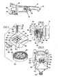
- a power tool having a locking system in accordance with the present invention is referred to generally as 10 in FIGURE 1.
- the power tool 10 shown is a portable grinder having a tool housing 12 including a housing member 14 at the front of the housing 12 and a handle portion 16 containing a line cord 18 electrically connected to switch 20.
- the switch 20 is in turn electrically connected to an electric motor (not shown) to rotatably drive an abrading element 22.
- the housing member 14 encloses a drive pinion 24 driven by the motor (not shown).
- the drive pinion 24 drives a driven element comprising gear 26, which is connected fast to tool spindle 28.
- the tool spindle 28 is rotatably journaled in bearings 30 and 32 and is drivingly connected at its exposed portion 34 to the abrading member 22 shown in FIGURE 1.
- the locking system is shown generally as 36 in FIGURES 2,3,4 and 5A to 5E.
- the locking system 36 includes an external recess 38 open at one end 40 thereof formed in the upper front portion of the housing member 14 and including a bottom portion 42.
- a retaining surface is defined by a bifurcated ledge 44 open at one end 46 adjacent the open end 40 of the external recess 38, and lying in a first plane.
- the locking system 36 further includes a lock member 48, biasing means 50 and retaining means 52.
- the lock member 48 is an elongated cylinder having a first or exposed end 54, a second or locking end 56 and a flange portion defined by an annular shoulder 58.
- the lock member 48- is slideably movable in a lock channel 60 along an axis 61 a first distance d' (shown in phantom in FIGURES 2 and 5E) from its normal position, to enter one of a plurality of driven element lock cavities 62, thereby retaining or locking the driven element 26 against movement relative to the housing member 14, the lock cavities 62 being registrable with lock channel 60.
- the lock member 48 is movable a second, longer predetermined distance d 2 from its normal position, along the lock channel 60 so that the lock member exposed end 54 is substantially flush with the recess bottom portion 42. Accordingly, as shown in FIGURE 3, the annular shoulder 58 is located a third predetermined distance d 3 from the exposed end 54, which is related to distance d 2 .
- the retaining means 52 includes a retaining member such as a disc or washer 64 defining an aperture 66 and having a lower surface 68.
- the retaining member 64 is slideably mounted in the housing member external recess 38 in a second plane. Referring to FIGURES 3 and 4, the retaining member 64, when fully mounted in the tool 12, is trapped between the recess bottom portion 40 and the bifurcated ledge 44, with the exposed end 54 of the lock member 48 engaging the retaining member 64 via aperture 66. Thus both the bifurcated ledge 44 and the retaining member 64 intersect the lock member axis 61, in their respective first and second planes.
- FIGURE 5E shows that the biasing means 50 includes a coil spring coaxially mounted in the lock channel 60 about the lock member 48, such that one end bears against lock member shoulder 58, and the other end is trapped against a reduced-diameter portion 70 of the lock channel 60.
- the biasing means 50 normally urges the lock member 48 out of engagement with the lock cavity 62 of driven element 26, and further normally urges the lock member 48 into retaining engagement with the retaining member 64.
- the shoulder 58 bears against retaining member 64, which in turn is retained by ledge 44 against vertical movement and by lock member 48 against transverse movement.
- spring 50 is part of a means for simultaneously maintaining both the lock member 48 and the retaining member 64 connected to the housing 12, and for selectively releasing the lock member 48 from the housing 12 responsive to operator actuation of the lock member 48.
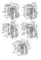
- FIGURES 5A to 5E show the sequence of operation in replacing a damaged lock member.
- a damaged lock member 48' is automatically retained in the housing 12 by the just-described coaction of the elements of the locking system 36.
- the operator depresses the lock member 48' against the urging of the biasing means 50, as shown by arrow 72 in FIGURE 5B, until the first or exposed end 54 of lock member 48' is removed from locking or retaining engagement with retaining member aperture 66, the exposed end 54 being immediately below the retaining member lower surface 68.
- the retaining member 64 is slideably moved transversely of the lock member 48. It can be seen that a portion of the retaining member 64 actually slides over the exposed end 54 of the lock member, thereby assisting in maintaining the lock member 48' out of locking engagement with retaining member 64. At this point, the lock member has travelled the second predetermined distance, d 2 , being deeply inserted into the drive element lock cavity 62.
- FIGURE 5C the retaining member 64 has been moved far enough, in the direction shown by arrow 7 4 , to allow the lock member 48' to be freely removed from the housing member 14, as shown by arrow 76.
- a replacement lock member 48 when a replacement lock member 48 is provided, it is first inserted into the housing member 14, again, against the urging of the biasing means 50 in the direction shown by arrow 78, until the lock member exposed end 54 once again can clear the retaining member lower surface 68, the lock member having again travelled the second predetermined distance d 2 in the lock channel 60 and into engagement with driven member lock cavity 62. Then the retaining member 64 may be inserted in the direction shown by arrow 80 until its aperture 66 is once again in registration with lock channel 60.
- FIGURE 5E the lock member 48 is shown after being released by the operator, now once again, at the urging of the biasing means 50, automatically retaining the retaining member 64 in the housing and being retained therein in turn by the retaining member 64.
- both the retaining member 64 and the lock member 48 are completely accessible to the operator from outside the housing, there by precluding any necessity for disassembling the power tool to replace the lock member 48 (or the retaining member 64). Also the assembled locking system maintains both the lock member exposed end 54, as well as the retaining member 64, secreted within the housing member recess 38.
Applications Claiming Priority (2)
| Application Number | Priority Date | Filing Date | Title |
|---|---|---|---|
| US522010 | 1983-08-11 | ||
| US06/522,010 US4489525A (en) | 1983-08-11 | 1983-08-11 | Replaceable spindle lock system |
Publications (3)
| Publication Number | Publication Date |
|---|---|
| EP0133740A2 true EP0133740A2 (fr) | 1985-03-06 |
| EP0133740A3 EP0133740A3 (en) | 1986-03-19 |
| EP0133740B1 EP0133740B1 (fr) | 1989-08-16 |
Family
ID=24079058
Family Applications (1)
| Application Number | Title | Priority Date | Filing Date |
|---|---|---|---|
| EP84304001A Expired EP0133740B1 (fr) | 1983-08-11 | 1984-06-14 | Dispositif de verrouillage pour outillage motorisé |
Country Status (6)
| Country | Link |
|---|---|
| US (1) | US4489525A (fr) |
| EP (1) | EP0133740B1 (fr) |
| AU (1) | AU579581B2 (fr) |
| CA (1) | CA1241843A (fr) |
| DE (1) | DE3479408D1 (fr) |
| ES (1) | ES8604444A1 (fr) |
Families Citing this family (32)
| Publication number | Priority date | Publication date | Assignee | Title |
|---|---|---|---|---|
| IT1266572B1 (it) * | 1993-07-30 | 1997-01-09 | Guido Valentini | Congegno per il montaggio e la rimozione manuali di dischi operatori in utensili manuali per la lavorazione di superfici |
| US5496139A (en) * | 1994-09-19 | 1996-03-05 | Snap-On Incorporated | Collet lock arrangement for power tool |
| US5716263A (en) * | 1996-03-08 | 1998-02-10 | Jones; William C. | Device for cleaning, polishing or sanding |
| DE19803454B4 (de) * | 1998-01-30 | 2018-11-29 | Scintilla Ag | Handgeführte Schlagbohrmaschine mit einer Arretiervorrichtung |
| EP0982103B1 (fr) * | 1998-08-28 | 2001-07-11 | CEKA ELEKTROWERKZEUGE AG + Co.KG | Dispositif de verrouillage automatique pour une broche |
| DE10029898A1 (de) * | 2000-06-17 | 2001-12-20 | Bosch Gmbh Robert | Handwerkzeugmaschine |
| US6488286B2 (en) | 2000-08-21 | 2002-12-03 | Theodore G. Yaksich | Chuck and power driver having improved interface assembly |
| US6665940B2 (en) | 2001-02-26 | 2003-12-23 | Electrolux Home Products, Inc. | Trimmer with output shaft locking mechanism |
| US6488451B1 (en) * | 2001-03-07 | 2002-12-03 | Snap-On Technologies, Inc. | Drive shaft lock |
| US6834864B2 (en) | 2001-10-24 | 2004-12-28 | Power Tool Holders Incorporated | Chuck having quick change mechanism |
| US7547167B2 (en) | 2005-09-16 | 2009-06-16 | Robert Bosch Gmbh | Storage drawer for hand-held power tool |
| US7261166B2 (en) * | 2005-09-16 | 2007-08-28 | Robert Bosch Gmbh | Switch for power tool |
| US7424768B2 (en) * | 2005-09-16 | 2008-09-16 | Credo Technology Corporation | Handle for power tool |
| US20070180704A1 (en) * | 2006-02-07 | 2007-08-09 | Yi-Shan Chiu | Locking device for spline shaft of brush cutter |
| US20070180705A1 (en) * | 2006-02-08 | 2007-08-09 | Yi-Shan Chiu | Locking device for spline shaft of brush cutter |
| US20090209182A1 (en) * | 2006-09-05 | 2009-08-20 | Dynabrade, Inc. | Locking random orbital dual-action head assembly |
| US20100151775A1 (en) * | 2006-09-05 | 2010-06-17 | Dynabrade, Inc. | Locking random orbital dual-action head assembly with centering |
| US7713110B2 (en) * | 2006-09-05 | 2010-05-11 | Dynabrade, Inc. | Locking random orbital dual-action head assembly |
| US7988538B2 (en) * | 2006-10-13 | 2011-08-02 | Black & Decker Inc. | Large angle grinder |
| US7717191B2 (en) | 2007-11-21 | 2010-05-18 | Black & Decker Inc. | Multi-mode hammer drill with shift lock |
| US7854274B2 (en) | 2007-11-21 | 2010-12-21 | Black & Decker Inc. | Multi-mode drill and transmission sub-assembly including a gear case cover supporting biasing |
| US7770660B2 (en) | 2007-11-21 | 2010-08-10 | Black & Decker Inc. | Mid-handle drill construction and assembly process |
| US7762349B2 (en) | 2007-11-21 | 2010-07-27 | Black & Decker Inc. | Multi-speed drill and transmission with low gear only clutch |
| US7717192B2 (en) | 2007-11-21 | 2010-05-18 | Black & Decker Inc. | Multi-mode drill with mode collar |
| US7735575B2 (en) | 2007-11-21 | 2010-06-15 | Black & Decker Inc. | Hammer drill with hard hammer support structure |
| US7798245B2 (en) | 2007-11-21 | 2010-09-21 | Black & Decker Inc. | Multi-mode drill with an electronic switching arrangement |
| US8047242B2 (en) * | 2007-12-07 | 2011-11-01 | Black & Decker Inc. | Power tool with spindle lock |
| WO2009086594A1 (fr) * | 2008-01-07 | 2009-07-16 | Lachlan George Reid | Mécanisme de fixation pour un disque de coupe |
| US8011444B2 (en) * | 2009-04-03 | 2011-09-06 | Ingersoll Rand Company | Spindle locking assembly |
| US20110039482A1 (en) * | 2009-07-29 | 2011-02-17 | Terry Timmons | Grinder |
| DE102010063623A1 (de) * | 2010-12-21 | 2012-06-21 | Robert Bosch Gmbh | Getriebeanordnung für ein Elektrofahrzeug und Elektrowerkzeug |
| CN207189852U (zh) | 2017-06-05 | 2018-04-06 | 米沃奇电动工具公司 | 台锯 |
Citations (6)
| Publication number | Priority date | Publication date | Assignee | Title |
|---|---|---|---|---|
| US1649060A (en) * | 1925-10-31 | 1927-11-15 | Black & Decker Mfg Co | Portable power-driven rotary tool with spindle latch and handoperated chuck |
| US2807732A (en) * | 1957-01-04 | 1957-09-24 | Kurtovich Joseph | Electric drill with built-in chuck key |
| US3899852A (en) * | 1974-08-23 | 1975-08-19 | Singer Co | Spindle drive assembly for a surface-treating machine |
| US3936203A (en) * | 1974-08-06 | 1976-02-03 | Eagle-Picher Industries, Inc. | Pin retention device |
| DE2816398A1 (de) * | 1978-04-15 | 1979-10-25 | Licentia Gmbh | Winkelschleifer mit einer spannvorrichtung fuer die schleifscheibe in form eines spann- und druckflansches |
| GB2020771A (en) * | 1978-05-03 | 1979-11-21 | Philips Nv | Captively retaining screws |
Family Cites Families (5)
| Publication number | Priority date | Publication date | Assignee | Title |
|---|---|---|---|---|
| US1270808A (en) * | 1916-11-24 | 1918-07-02 | Charles H Franklin | Rotary tool. |
| US2101305A (en) * | 1937-08-13 | 1937-12-07 | Albertson & Co Inc | Sanding machine |
| US2211216A (en) * | 1938-02-11 | 1940-08-13 | Oster John Mfg Co | Small power driven tool |
| US2267781A (en) * | 1939-11-09 | 1941-12-30 | Albertson & Co Inc | Electric sanding machine |
| US3021723A (en) * | 1958-09-10 | 1962-02-20 | Diehl Mfg Co | Spindle locking means for portable tools |
-
1983
- 1983-08-11 US US06/522,010 patent/US4489525A/en not_active Expired - Fee Related
-
1984
- 1984-06-14 DE DE8484304001T patent/DE3479408D1/de not_active Expired
- 1984-06-14 EP EP84304001A patent/EP0133740B1/fr not_active Expired
- 1984-07-03 CA CA000457963A patent/CA1241843A/fr not_active Expired
- 1984-08-09 ES ES535006A patent/ES8604444A1/es not_active Expired
- 1984-08-10 AU AU31778/84A patent/AU579581B2/en not_active Ceased
Patent Citations (6)
| Publication number | Priority date | Publication date | Assignee | Title |
|---|---|---|---|---|
| US1649060A (en) * | 1925-10-31 | 1927-11-15 | Black & Decker Mfg Co | Portable power-driven rotary tool with spindle latch and handoperated chuck |
| US2807732A (en) * | 1957-01-04 | 1957-09-24 | Kurtovich Joseph | Electric drill with built-in chuck key |
| US3936203A (en) * | 1974-08-06 | 1976-02-03 | Eagle-Picher Industries, Inc. | Pin retention device |
| US3899852A (en) * | 1974-08-23 | 1975-08-19 | Singer Co | Spindle drive assembly for a surface-treating machine |
| DE2816398A1 (de) * | 1978-04-15 | 1979-10-25 | Licentia Gmbh | Winkelschleifer mit einer spannvorrichtung fuer die schleifscheibe in form eines spann- und druckflansches |
| GB2020771A (en) * | 1978-05-03 | 1979-11-21 | Philips Nv | Captively retaining screws |
Also Published As
| Publication number | Publication date |
|---|---|
| EP0133740A3 (en) | 1986-03-19 |
| ES8604444A1 (es) | 1986-02-01 |
| ES535006A0 (es) | 1986-02-01 |
| EP0133740B1 (fr) | 1989-08-16 |
| CA1241843A (fr) | 1988-09-13 |
| AU579581B2 (en) | 1988-12-01 |
| AU3177884A (en) | 1985-02-14 |
| US4489525A (en) | 1984-12-25 |
| DE3479408D1 (en) | 1989-09-21 |
Similar Documents
| Publication | Publication Date | Title |
|---|---|---|
| EP0133740B1 (fr) | Dispositif de verrouillage pour outillage motorisé | |
| CN102303307B (zh) | 动力工具系统 | |
| EP1339528B1 (fr) | Outil a main comportant un capteur destine a l'emission de signaux lors du remplacement de l'outil a main | |
| US3787973A (en) | Safety retracting mechanism for the lower guard of a portable saw | |
| EP2361732B1 (fr) | Outil électrique disposant d'un élément de commutation | |
| US3899852A (en) | Spindle drive assembly for a surface-treating machine | |
| US4493223A (en) | Gear shifting speed change apparatus for a rotary electric tool | |
| EP1859910A1 (fr) | Outil électrique doté de lames interchangeables et procédé | |
| EP2286659B1 (fr) | Outil électrique doté d'un ensemble de lames interchangeables et procédé d'échange de l'ensemble de lames | |
| EP0408987A2 (fr) | Outil électrique | |
| US4188682A (en) | Automobile cleaning and waxing tool | |
| DE10161452A1 (de) | Batteriebetriebene Werkzeuge | |
| US10434669B2 (en) | Electric shaver | |
| JP4804823B2 (ja) | 携帯丸鋸 | |
| DE202007001336U1 (de) | Haarschneidemaschine mit verbesserten Klingensteuer-Strukturen | |
| GB1601482A (en) | Apparatus for the separation by centrifugal force of the components of test samples in vessels of tubular form | |
| DE102021100884A1 (de) | Elektrische arbeitsmaschine, beleuchtungsaufsatz und verfahren zum ausstrahlen von licht von einer elektrischen arbeitsmaschine | |
| DE102017113988A1 (de) | Staubsammelvorrichtung für ein elektrisches Kraftwerkzeug, elektrisches Kraftwerkzeug und Staubsammelsystem | |
| CN101786185A (zh) | 便携式切割机 | |
| GB2057955A (en) | Dry-shaving apparatus | |
| DE19931368A1 (de) | Batteriebetriebene Tischsäge | |
| CN210309706U (zh) | 一种削笔器的笔芯粗细调节结构和应用有该笔芯粗细调节结构的削笔器 | |
| US2346778A (en) | Portable hand held electric tool | |
| US6820338B2 (en) | Electrical gardening tool with a replaceable working piece | |
| US4808862A (en) | Motorized tool with easily replaceable switch |
Legal Events
| Date | Code | Title | Description |
|---|---|---|---|
| PUAI | Public reference made under article 153(3) epc to a published international application that has entered the european phase |
Free format text: ORIGINAL CODE: 0009012 |
|
| 17P | Request for examination filed |
Effective date: 19841214 |
|
| AK | Designated contracting states |
Designated state(s): DE FR GB IT NL SE |
|
| PUAL | Search report despatched |
Free format text: ORIGINAL CODE: 0009013 |
|
| AK | Designated contracting states |
Kind code of ref document: A3 Designated state(s): DE FR GB IT NL SE |
|
| 17Q | First examination report despatched |
Effective date: 19870723 |
|
| ITF | It: translation for a ep patent filed |
Owner name: GUZZI E RAVIZZA S.R.L. |
|
| GRAA | (expected) grant |
Free format text: ORIGINAL CODE: 0009210 |
|
| AK | Designated contracting states |
Kind code of ref document: B1 Designated state(s): DE FR GB IT NL SE |
|
| REF | Corresponds to: |
Ref document number: 3479408 Country of ref document: DE Date of ref document: 19890921 |
|
| ET | Fr: translation filed | ||
| PLBE | No opposition filed within time limit |
Free format text: ORIGINAL CODE: 0009261 |
|
| STAA | Information on the status of an ep patent application or granted ep patent |
Free format text: STATUS: NO OPPOSITION FILED WITHIN TIME LIMIT |
|
| 26N | No opposition filed | ||
| ITTA | It: last paid annual fee | ||
| EAL | Se: european patent in force in sweden |
Ref document number: 84304001.5 |
|
| PGFP | Annual fee paid to national office [announced via postgrant information from national office to epo] |
Ref country code: GB Payment date: 19950516 Year of fee payment: 12 |
|
| PGFP | Annual fee paid to national office [announced via postgrant information from national office to epo] |
Ref country code: NL Payment date: 19950522 Year of fee payment: 12 |
|
| PGFP | Annual fee paid to national office [announced via postgrant information from national office to epo] |
Ref country code: FR Payment date: 19950526 Year of fee payment: 12 Ref country code: DE Payment date: 19950526 Year of fee payment: 12 |
|
| PGFP | Annual fee paid to national office [announced via postgrant information from national office to epo] |
Ref country code: SE Payment date: 19950530 Year of fee payment: 12 |
|
| PG25 | Lapsed in a contracting state [announced via postgrant information from national office to epo] |
Ref country code: GB Effective date: 19960614 |
|
| PG25 | Lapsed in a contracting state [announced via postgrant information from national office to epo] |
Ref country code: SE Effective date: 19960615 |
|
| PG25 | Lapsed in a contracting state [announced via postgrant information from national office to epo] |
Ref country code: NL Effective date: 19970101 |
|
| GBPC | Gb: european patent ceased through non-payment of renewal fee |
Effective date: 19960614 |
|
| PG25 | Lapsed in a contracting state [announced via postgrant information from national office to epo] |
Ref country code: FR Effective date: 19970228 |
|
| PG25 | Lapsed in a contracting state [announced via postgrant information from national office to epo] |
Ref country code: DE Effective date: 19970301 |
|
| EUG | Se: european patent has lapsed |
Ref document number: 84304001.5 |
|
| NLV4 | Nl: lapsed or anulled due to non-payment of the annual fee |
Effective date: 19970101 |
|
| REG | Reference to a national code |
Ref country code: FR Ref legal event code: ST |