EP0133737A2 - Bâti en sous-sol pour appareillage électrique - Google Patents
Bâti en sous-sol pour appareillage électrique Download PDFInfo
- Publication number
- EP0133737A2 EP0133737A2 EP84303532A EP84303532A EP0133737A2 EP 0133737 A2 EP0133737 A2 EP 0133737A2 EP 84303532 A EP84303532 A EP 84303532A EP 84303532 A EP84303532 A EP 84303532A EP 0133737 A2 EP0133737 A2 EP 0133737A2
- Authority
- EP
- European Patent Office
- Prior art keywords
- frame
- vault
- mounting
- wall
- pivotal
- Prior art date
- Legal status (The legal status is an assumption and is not a legal conclusion. Google has not performed a legal analysis and makes no representation as to the accuracy of the status listed.)
- Granted
Links
Images
Classifications
-
- H—ELECTRICITY
- H02—GENERATION; CONVERSION OR DISTRIBUTION OF ELECTRIC POWER
- H02B—BOARDS, SUBSTATIONS OR SWITCHING ARRANGEMENTS FOR THE SUPPLY OR DISTRIBUTION OF ELECTRIC POWER
- H02B7/00—Enclosed substations, e.g. compact substations
- H02B7/06—Distribution substations, e.g. for urban network
- H02B7/08—Underground substations
-
- G—PHYSICS
- G02—OPTICS
- G02B—OPTICAL ELEMENTS, SYSTEMS OR APPARATUS
- G02B6/00—Light guides; Structural details of arrangements comprising light guides and other optical elements, e.g. couplings
- G02B6/46—Processes or apparatus adapted for installing or repairing optical fibres or optical cables
- G02B6/50—Underground or underwater installation; Installation through tubing, conduits or ducts
- G02B6/501—Underground or underwater installation; Installation through tubing, conduits or ducts underground installation of connection boxes
-
- H—ELECTRICITY
- H02—GENERATION; CONVERSION OR DISTRIBUTION OF ELECTRIC POWER
- H02B—BOARDS, SUBSTATIONS OR SWITCHING ARRANGEMENTS FOR THE SUPPLY OR DISTRIBUTION OF ELECTRIC POWER
- H02B1/00—Frameworks, boards, panels, desks, casings; Details of substations or switching arrangements
- H02B1/26—Casings; Parts thereof or accessories therefor
- H02B1/50—Pedestal- or pad-mounted casings; Parts thereof or accessories therefor
- H02B1/505—Pedestal- or pad-mounted casings; Parts thereof or accessories therefor retractable installations
Definitions
- This invention relates generally to apparatus and methods for mounting equipment in vaults and particularly to apparatus and methods for mounting electrical equipment in underground vaults. Still more particularly, this invention relates to apparatus and methods for mounting electrical equipment, such as that used in telephonic communications systems, in underground vaults while including means for removing the equipment from the vault for providing access to the equipment.
- Underground telephone installations in particular, frequently require a person to gain access to equipment located in underground vaults having upper covers that are approximately flush with the ground level.
- the persons had to either physically enter the vault, which therefore had to be made large enough to accomodate the person and the equipment; or the equipment had to be lifted from the vault either manually or by use of machinery external to the vault.
- the equipment may be relatively small, it may also be too heavy for an individual to easily lift without the aid of other equipment.
- the use of other equipment to lift the electrical apparatus from the vault requires that the equipment be transported from one vault to another for lifting the equipment from the vault.
- the present invention provides a convenient apparatus and method for mounting equipment in an underground vault to provide convenient access to the equipment whenever such access is necessary.
- the vault mount of the present invention includes a frame having one end thereof permanently pivotally mounted to a first wall of the vault and the other end of the frame releasably attached to a second wall of the vault. Suitable springs are mounted between the first wall of the vault and the frame to urge the frame to pivot about the mounting to the first wall. When the second end of the frame is released from its wall mount, the frame and the apparatus mounted thereon pivots from a generally horizontal position in the vault to a generally vertical position with the equipment mounted on the frame extending out of the vault.
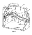
- a vault 10 which may be formed of concrete or other suitable material, has an upper cover 12 that is preferably removable.
- a vault mount 14 according to the invention is shown mounted between a first wall 16 of the vault 10 and a second wall 18.
- a box 20 shown in phantom lines in Figure 1 represents device such as a piece of electrical equipment which must be mounted in the vault 10. Details of the structure of the box to be mounted in the vault 10 are not essential to the present invention and are, therefore, not explained in detail herein. It is, however, essential that if the box 10 is connected to other equipment (not shown), then the connections (not shown) must sufficiently long and flexible to permit the box 10 to be raised a short distance out of the vault as described herein.
- the vault mount 14 comprises a pair of rails 22 and 24, each being pivotally mounted to the first wall 16 by suitable mounting brackets 26 and 28, respectively.
- Mounting brackets 26 and 28 may comprise any convenient pivotal mounting devices.
- the bracket 26, for example, is shown to comprise a flat, rectangular plate 30, which a pair of screws 32 and 34, or other suitable fastening means, secure to the first wall 16.
- a projection 36 extends generally perpendicularly from the rectangular plate 30 and includes a cylindrical passage therethrough for receiving a cylindrical stud 38 that extends from the end of the rail 22.
- the bracket 28 may be formed similarly to the bracket 32 and therefore is not described in further detail.
- the rails 22 and 24 are generally parallel and extend generally perpendicularly away from the wall 16.
- the rail 22 includes an inclined portion 40 that extends at an angle from the generally horizontal rail 22, as shown in Figure 1, into the vault 10.
- the rail 24 includes an inclined portion 42 similar to the inclined portion 40.
- a seat 44 extends from the inclined portions 40 and 42.
- the seat 44 preferably has a generally rectangular configuration formed of an extension 46 of the rail 22 connected to the inclined portion 40 and an extension 48 of the rail 24 connected to the inclined portion 42.
- the extensions 46 and 48 are preferably generally parallel and are connected by crossbars 52 and 54 to provide a rigid structure.
- the extensions 46 and 48 may include a plurality of passages 56 therethrough to provide convenient means for attaching the box 20 to the seat 44.
- the rail 24 has an end portion 58 which extends beyond the seat 44.
- the end 58 includes a passage therein for rotatably mounting a key 60, which includes an elongate shaft 62.
- a bracket 64 having a slot 66 therein extends away from the wall 18 to align the center of the slot 66 with the elongate shaft 62.
- the elongate shaft 62 has a proximal end 63 having a handle 70 formed thereon and a distal end 65 having a cross piece 68 connected perpendicularly thereto.
- the distal end 65 extends through the slot 66, and the cross piece 68 is oriented generally perpendicularly to the slot 66 to retain the end 58 against upward motion away from the bracket 64.
- the handle 70 attached to the proximal end 63 of the shaft 62 provides convenient means for rotating the cross piece 68 to either align the cross piece 68 parallel with the slot 66 to permit the frame 44 to be pivoted to lift the box 20 out of the vault 10 or to orient the cross piece 68 perpendicular to the slot to retain the box 20 and frame 14 stationary in the vault 10.
- the shaft 62 preferably has an enlarged portion which rotatably mounts the shaft 62 in the end 58 of the rail 24 to retain the shaft 62 in a generally perpendicular orientation relative to the end 58.
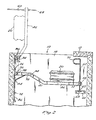
- the vault mount 14 preferably includes a pair of torsion springs 74 and 76 which provide means for biasing the frame 44 toward pivotal motion about the brackets 26 and 28 to lift the box 20 out of the vault 10 to the position shown in phantom lines in Figure 2.
- the torsion spring 74 includes an end 78 engaged with the rail 22, a central portion 80 retained adjacent the wall 16 a plurality of brackets 82-84 and an end 86 spring biased against the wall 16 by torsion in the central portion 86.
- the torsion spring 76 includes an end 88 engaged with the rail 24, a central portion 90 retained adjacent by the brackets 82 and 83 adjacent the wall 16 and an end 92 urged against the wall 16 by torsion in the central portion 90.
- the central portions 80 and 90 of the torsion springs 74 and 76, respectively, are under torsion to urge the frame 44 to rotate counter-clockwise about the brackets 26 and 28 as viewed Figures 1 and 2 to tend to lift the box 20 to the elevated position shown in phantom lines in Figure 2.
- the rail 22 preferably includes a projection 94 extending therefrom in general parallel alignment with the wall 16.
- a latch 96 is suitably mounted to the wall 16 to receive the projection 94 therein as shown in Figure 2 when the box is. in the elevated position.
- Assembly of the vault mount 14 may be done in a number of sequential steps, however, a satisfactory method of assembly is to first mount the brackets 26 and 28 to the wall 16 and to mount the bracket 64 to the wall 18.
- the seat 44 should be rotated into the elevated position to facilitate installation of the torsion springs 74 and 76 because when the seat 44 is in the elevated position, the torsion spring forces in the torsion springs 74 and 76 are at the minimum possible values for the fully assembled structure.
- the latch 96 should be installed when the seat is in the elevated position to insure that the projection 94 properly engages the latch 96.
- the central portion 80 of the torsion spring 74 should be properly positioned on the wall 16 to insure that the end 78 of the torsion spring 74 remains engaged with the rail 22 at all positions thereof between and including the upper position as shown in phantom lines in Figure 2 and the lower position as shown in Figures 1 and 2.
- the torsion spring 76 must be similarly aligned to insure that the end 88 thereof remains in contact with the rail 24.
- the torsion springs 74 and 76 may be formed such that there is very little or no torsion spring force on the rails 22 and 24 when the seat 44 is in the elevated position. Having the rail 22 to the wall 16 with the projection 94 being engaged in the latch 96 insures that the box 20 remains in a stable position so that a person may perform desired tasks on equipment located in the box 20 without undesirable movement thereof.
- the box 20 is secured to the seat 44.
- the box 20 and the seat 44 are rotated clockwise about the brackets 26 and 28 to position the box 20 within the vault 10.
- the crossmember 68 of the key 60 is aligned parallel with the slot 66 and inserted therethrough. After the crossmember 68 has passed completely through the slot 66 in the bracket 64, rotation of the handle 70 to place a crossmember 68 approximately perpendicular to the slot 66 locks the frame 44 to the bracket 64.
- the spring biase forces from the torsion spring 74 and 76 urge the crossmember 68 against the underside of the bracket 64 to frictionally engage the crossmemher 68 and the bracket 64 so that sma11 vibrations do not turn crossmember 68 into alignment with the slot 66 thereby inadvertently releasing the seat 44 from the locked down position.
- a person In order to gain access to the box 20, a person must first remove the cover 12 from the vault 10 and then rotate the key 60, preferably by grasping the handle 70 and exerting a force thereon to rotate the shaft 62 so that the cross piece 68 is aligned parallel with the slot 66. Rotation of the handle 62 may- be facilitated by exerting a downward force on the handle or on the box 20 to relieve the frictional engagement of the cross piece 68 with the underside of the bracket 64. After the key 60 has been released from the bracket 64, the individual should continue to exert a clockwise torque on the vault mount 14 as viewed in Figures 1 and 2 in order to prevent it from rapidly springing upward against the wall 16.
- the seat 44 should be permitted to rotate slowly in a counter-clockwise direction until the projection 94 is retained within the latch 96. After the box 20 has been elevated and the projection 94 secured within the latch 96, a person may gain easy access to the box 20 to perform desired tasks upon equipment therein.
Priority Applications (1)
| Application Number | Priority Date | Filing Date | Title |
|---|---|---|---|
| AT84303532T ATE48206T1 (de) | 1983-08-15 | 1984-05-25 | Unterflurgestell fuer elektrisches geraet. |
Applications Claiming Priority (2)
| Application Number | Priority Date | Filing Date | Title |
|---|---|---|---|
| US06/522,808 US4541209A (en) | 1983-08-15 | 1983-08-15 | Vault mount for electrical apparatus |
| US522808 | 2000-03-10 |
Publications (3)
| Publication Number | Publication Date |
|---|---|
| EP0133737A2 true EP0133737A2 (fr) | 1985-03-06 |
| EP0133737A3 EP0133737A3 (en) | 1986-09-17 |
| EP0133737B1 EP0133737B1 (fr) | 1989-11-23 |
Family
ID=24082447
Family Applications (1)
| Application Number | Title | Priority Date | Filing Date |
|---|---|---|---|
| EP84303532A Expired EP0133737B1 (fr) | 1983-08-15 | 1984-05-25 | Bâti en sous-sol pour appareillage électrique |
Country Status (4)
| Country | Link |
|---|---|
| US (1) | US4541209A (fr) |
| EP (1) | EP0133737B1 (fr) |
| AT (1) | ATE48206T1 (fr) |
| DE (1) | DE3480574D1 (fr) |
Cited By (5)
| Publication number | Priority date | Publication date | Assignee | Title |
|---|---|---|---|---|
| FR2713307A1 (fr) * | 1993-11-30 | 1995-06-09 | Bonis Francoise | Châssis support escamotable, pour appareillage de sources ou d'émission d'énergies diverses. |
| FR2742018A1 (fr) * | 1995-12-05 | 1997-06-06 | Barat Sa | Dispositif de coffre de connexion electrique ou analogue, pour le reseau urbain |
| ES2178967A1 (es) * | 2001-05-18 | 2003-01-01 | Garcia Jose Cambronero | Transformador protegido por tapas y banda de material protector y aislante con doble sistema de anclaje, a bancada y a carril y una sola hilera de terminales. |
| EP2056145A3 (fr) * | 2007-10-30 | 2009-12-16 | ADC Telecommunications, Inc. | Élévation d'une enceinte de terminal dans des applications souterraines |
| FR3062860A1 (fr) * | 2017-02-13 | 2018-08-17 | Fonderies De Brousseval & Montreuil | Grille anti-chutes a support de boitier d'epissurage integre |
Families Citing this family (9)
| Publication number | Priority date | Publication date | Assignee | Title |
|---|---|---|---|---|
| FR2751140B1 (fr) * | 1996-07-15 | 1999-04-02 | Rouere Richard Jean De | Dispositif elevateur d'assistance et de guidage destine a controler un mouvement de montee descente d'un support de boitiers d'interface entre des reseaux de cables enterres et la distribution aux points d'utilisation |
| US5925848A (en) * | 1997-10-21 | 1999-07-20 | Dalworth Concrete Products, Inc. | Concrete step-in electronic cabinet system |
| US6503390B1 (en) * | 2000-02-11 | 2003-01-07 | Solidification Products International, Inc. | Filtration of hydrocarbon containing liquid |
| US6401400B1 (en) | 2000-03-15 | 2002-06-11 | Newbasis, Llc | Industrial vault |
| US6861584B2 (en) * | 2003-04-04 | 2005-03-01 | Stockdale Communications Incorporated | Flush-to-grade vault with wall-mounted cross-connect panels |
| US7922269B2 (en) * | 2006-10-17 | 2011-04-12 | Adc Telecommunications, Inc. | Cabinet assembly including a scissors lift |
| US8158010B2 (en) * | 2009-03-03 | 2012-04-17 | Herb Pearse | Filter sleeve for enabling waste water discharge directly into the environment |
| US9851523B2 (en) | 2015-09-22 | 2017-12-26 | Go!Foton Holdings, Inc. | Apparatus for cable routing |
| US10310206B2 (en) | 2017-05-22 | 2019-06-04 | Go!Foton Holdings, Inc. | Apparatus for cable routing |
Citations (4)
| Publication number | Priority date | Publication date | Assignee | Title |
|---|---|---|---|---|
| US1778373A (en) * | 1929-05-02 | 1930-10-14 | Frederic C Shumaker | Train-order-delivery light |
| US2350140A (en) * | 1943-04-28 | 1944-05-30 | Wilton John | Airplane |
| US3522970A (en) * | 1968-06-21 | 1970-08-04 | Ltv Aerospace Corp | Latch mechanism for folding seat |
| DE1949694A1 (de) * | 1969-10-02 | 1971-04-15 | Ebe Elektro Bau Elemente Gmbh | Kabelverteiler |
Family Cites Families (5)
| Publication number | Priority date | Publication date | Assignee | Title |
|---|---|---|---|---|
| US2895702A (en) * | 1956-09-18 | 1959-07-21 | Eldridge M Pierce | Thermos jug holder |
| US3672103A (en) * | 1969-12-31 | 1972-06-27 | City Of Fort Collins | Modular utility vault |
| US3617608A (en) * | 1970-04-15 | 1971-11-02 | Repco Products Corp | Underground electrical conductor housing for accommodating a transformer |
| SE7809720L (sv) * | 1978-09-15 | 1980-03-16 | Jonsson Lennart Christer Bjarn | Servisanordning for fartyg vid en kajanleggning |
| FR2509404A1 (fr) * | 1981-07-10 | 1983-01-14 | Dba | Frein a tambour a rattrapage automatique d'usure |
-
1983
- 1983-08-15 US US06/522,808 patent/US4541209A/en not_active Expired - Lifetime
-
1984
- 1984-05-25 AT AT84303532T patent/ATE48206T1/de not_active IP Right Cessation
- 1984-05-25 EP EP84303532A patent/EP0133737B1/fr not_active Expired
- 1984-05-25 DE DE8484303532T patent/DE3480574D1/de not_active Expired
Patent Citations (4)
| Publication number | Priority date | Publication date | Assignee | Title |
|---|---|---|---|---|
| US1778373A (en) * | 1929-05-02 | 1930-10-14 | Frederic C Shumaker | Train-order-delivery light |
| US2350140A (en) * | 1943-04-28 | 1944-05-30 | Wilton John | Airplane |
| US3522970A (en) * | 1968-06-21 | 1970-08-04 | Ltv Aerospace Corp | Latch mechanism for folding seat |
| DE1949694A1 (de) * | 1969-10-02 | 1971-04-15 | Ebe Elektro Bau Elemente Gmbh | Kabelverteiler |
Cited By (5)
| Publication number | Priority date | Publication date | Assignee | Title |
|---|---|---|---|---|
| FR2713307A1 (fr) * | 1993-11-30 | 1995-06-09 | Bonis Francoise | Châssis support escamotable, pour appareillage de sources ou d'émission d'énergies diverses. |
| FR2742018A1 (fr) * | 1995-12-05 | 1997-06-06 | Barat Sa | Dispositif de coffre de connexion electrique ou analogue, pour le reseau urbain |
| ES2178967A1 (es) * | 2001-05-18 | 2003-01-01 | Garcia Jose Cambronero | Transformador protegido por tapas y banda de material protector y aislante con doble sistema de anclaje, a bancada y a carril y una sola hilera de terminales. |
| EP2056145A3 (fr) * | 2007-10-30 | 2009-12-16 | ADC Telecommunications, Inc. | Élévation d'une enceinte de terminal dans des applications souterraines |
| FR3062860A1 (fr) * | 2017-02-13 | 2018-08-17 | Fonderies De Brousseval & Montreuil | Grille anti-chutes a support de boitier d'epissurage integre |
Also Published As
| Publication number | Publication date |
|---|---|
| ATE48206T1 (de) | 1989-12-15 |
| EP0133737A3 (en) | 1986-09-17 |
| EP0133737B1 (fr) | 1989-11-23 |
| DE3480574D1 (en) | 1989-12-28 |
| US4541209A (en) | 1985-09-17 |
Similar Documents
| Publication | Publication Date | Title |
|---|---|---|
| US4541209A (en) | Vault mount for electrical apparatus | |
| US7431594B2 (en) | Telescoping weather resistant box | |
| US8698692B2 (en) | Apparatus for mounting an object to a railing | |
| US5058336A (en) | Hinged flange pole | |
| US5181120A (en) | Surveillance camera system | |
| US20010019002A1 (en) | Retractable cable reel | |
| US8472179B1 (en) | Actuation mechanism for vertical insertion, retention and extraction of an electronic component | |
| US5050869A (en) | Portable exercise machine | |
| CA1223057A (fr) | Support de montage en chambre pour materiels electriques | |
| US4545558A (en) | Platform suspending davit mounting apparatus and method | |
| US4823381A (en) | Security cover for telephone line installation backboard and method of retrofitting the same | |
| EP0040167A1 (fr) | Assemblage de verrou à serrage ajustable | |
| US20060268368A1 (en) | Document holding fixture | |
| US8152542B2 (en) | Electrical connector enclosure | |
| US3840711A (en) | Telephone wall mount | |
| CN115635447A (zh) | 一种故障指示器的安装工具 | |
| JPH1182881A (ja) | 機器用調整脚 | |
| KR200451188Y1 (ko) | 흡착판을 이용한 안테나 고정 장치 | |
| JPH08208175A (ja) | 墓石据付け用ハンガー | |
| CN212849499U (zh) | 一种配电箱安装支架 | |
| JPH0644246Y2 (ja) | 架台搭載引出し型電源装置の電源ユニット引留め構造 | |
| KR102511475B1 (ko) | 공공건물의 옥내 랜 회선 지지를 위한 통신선 고정기구 | |
| JPS597822Y2 (ja) | 通信装置用配線盤の構造 | |
| JPH063044Y2 (ja) | カバーの取付け装置 | |
| JP3168288B2 (ja) | 開口部の蓋用掛止具 |
Legal Events
| Date | Code | Title | Description |
|---|---|---|---|
| PUAI | Public reference made under article 153(3) epc to a published international application that has entered the european phase |
Free format text: ORIGINAL CODE: 0009012 |
|
| AK | Designated contracting states |
Designated state(s): AT BE CH DE FR GB IT LI LU NL SE |
|
| PUAL | Search report despatched |
Free format text: ORIGINAL CODE: 0009013 |
|
| AK | Designated contracting states |
Kind code of ref document: A3 Designated state(s): AT BE CH DE FR GB IT LI LU NL SE |
|
| 17P | Request for examination filed |
Effective date: 19861031 |
|
| 17Q | First examination report despatched |
Effective date: 19880419 |
|
| ITF | It: translation for a ep patent filed |
Owner name: ING. ZINI MARANESI & C. S.R.L. |
|
| GRAA | (expected) grant |
Free format text: ORIGINAL CODE: 0009210 |
|
| AK | Designated contracting states |
Kind code of ref document: B1 Designated state(s): AT BE CH DE FR GB IT LI LU NL SE |
|
| REF | Corresponds to: |
Ref document number: 48206 Country of ref document: AT Date of ref document: 19891215 Kind code of ref document: T |
|
| REF | Corresponds to: |
Ref document number: 3480574 Country of ref document: DE Date of ref document: 19891228 |
|
| ET | Fr: translation filed | ||
| PG25 | Lapsed in a contracting state [announced via postgrant information from national office to epo] |
Ref country code: GB Effective date: 19900525 Ref country code: AT Effective date: 19900525 |
|
| PG25 | Lapsed in a contracting state [announced via postgrant information from national office to epo] |
Ref country code: SE Effective date: 19900526 |
|
| PG25 | Lapsed in a contracting state [announced via postgrant information from national office to epo] |
Ref country code: LU Free format text: LAPSE BECAUSE OF NON-PAYMENT OF DUE FEES Effective date: 19900531 Ref country code: LI Effective date: 19900531 Ref country code: CH Effective date: 19900531 Ref country code: BE Effective date: 19900531 |
|
| PLBE | No opposition filed within time limit |
Free format text: ORIGINAL CODE: 0009261 |
|
| STAA | Information on the status of an ep patent application or granted ep patent |
Free format text: STATUS: NO OPPOSITION FILED WITHIN TIME LIMIT |
|
| 26N | No opposition filed | ||
| BERE | Be: lapsed |
Owner name: ASSOCIATED CONCRETE PRODUCTS INC. Effective date: 19900531 |
|
| PG25 | Lapsed in a contracting state [announced via postgrant information from national office to epo] |
Ref country code: NL Effective date: 19901201 |
|
| NLV4 | Nl: lapsed or anulled due to non-payment of the annual fee | ||
| GBPC | Gb: european patent ceased through non-payment of renewal fee | ||
| PG25 | Lapsed in a contracting state [announced via postgrant information from national office to epo] |
Ref country code: FR Effective date: 19910131 |
|
| REG | Reference to a national code |
Ref country code: CH Ref legal event code: PL |
|
| PG25 | Lapsed in a contracting state [announced via postgrant information from national office to epo] |
Ref country code: DE Effective date: 19910201 |
|
| REG | Reference to a national code |
Ref country code: FR Ref legal event code: ST |
|
| EUG | Se: european patent has lapsed |
Ref document number: 84303532.0 Effective date: 19910115 |