EP0133245B1 - A method for forming an electric resistance welded steel pipe - Google Patents
A method for forming an electric resistance welded steel pipe Download PDFInfo
- Publication number
- EP0133245B1 EP0133245B1 EP84108542A EP84108542A EP0133245B1 EP 0133245 B1 EP0133245 B1 EP 0133245B1 EP 84108542 A EP84108542 A EP 84108542A EP 84108542 A EP84108542 A EP 84108542A EP 0133245 B1 EP0133245 B1 EP 0133245B1
- Authority
- EP
- European Patent Office
- Prior art keywords
- forming
- skelp
- rounded
- bending
- roll
- Prior art date
- Legal status (The legal status is an assumption and is not a legal conclusion. Google has not performed a legal analysis and makes no representation as to the accuracy of the status listed.)
- Expired
Links
Images


Classifications
-
- B—PERFORMING OPERATIONS; TRANSPORTING
- B21—MECHANICAL METAL-WORKING WITHOUT ESSENTIALLY REMOVING MATERIAL; PUNCHING METAL
- B21C—MANUFACTURE OF METAL SHEETS, WIRE, RODS, TUBES, PROFILES OR LIKE SEMI-MANUFACTURED PRODUCTS OTHERWISE THAN BY ROLLING; AUXILIARY OPERATIONS USED IN CONNECTION WITH METAL-WORKING WITHOUT ESSENTIALLY REMOVING MATERIAL
- B21C37/00—Manufacture of metal sheets, rods, wire, tubes, profiles or like semi-manufactured products, not otherwise provided for; Manufacture of tubes of special shape
- B21C37/06—Manufacture of metal sheets, rods, wire, tubes, profiles or like semi-manufactured products, not otherwise provided for; Manufacture of tubes of special shape of tubes or metal hoses; Combined procedures for making tubes, e.g. for making multi-wall tubes
- B21C37/08—Making tubes with welded or soldered seams
-
- B—PERFORMING OPERATIONS; TRANSPORTING
- B21—MECHANICAL METAL-WORKING WITHOUT ESSENTIALLY REMOVING MATERIAL; PUNCHING METAL
- B21D—WORKING OR PROCESSING OF SHEET METAL OR METAL TUBES, RODS OR PROFILES WITHOUT ESSENTIALLY REMOVING MATERIAL; PUNCHING METAL
- B21D5/00—Bending sheet metal along straight lines, e.g. to form simple curves
- B21D5/06—Bending sheet metal along straight lines, e.g. to form simple curves by drawing procedure making use of dies or forming-rollers, e.g. making profiles
- B21D5/10—Bending sheet metal along straight lines, e.g. to form simple curves by drawing procedure making use of dies or forming-rollers, e.g. making profiles for making tubes
- B21D5/12—Bending sheet metal along straight lines, e.g. to form simple curves by drawing procedure making use of dies or forming-rollers, e.g. making profiles for making tubes making use of forming-rollers
Definitions
- the present invention relates to a method for forming a skelp in preparation of an electric resistance welded steel pipe according to the precharacterizing part of claim 1 as known from US-A-2234450.
- a flat skelp trimmed in a width corresponding to the unfolded circumferential length of the desired pipe is first formed into a semicircular rounded skelp by successively passing through several forming rolls for the initial and intermediate forming stages followed by the stable forming of the edges through fin pass rolls at the finishing stage to finish the rounded skelp to have the predetermined shape and dimensions which is then subjected to the upset welding of the marginal edges to form the seam by means of a squeeze roll.
- Proper selection of the roll-forming process of the skelp before welding is very important because it is the determining factor for the quality of welding, yield in the forming, productivity and the operating rate of the mill, investment for the facilities, cost for rolls and the like.
- the above described forming method of the electric resistance welded steel pipe is essentially a combination of the selected cross-sectional configuration of the skelp, i.e. forming flower or form, in the forming process as a software-like technology and the actual selected type of the forming process in the forming facilities as a hardware.
- the forming flower or form here implied means the patterns by which the successively changing cross sectional configuration of the skelp is expressed along the line of the sequence of the rolls at each of which the running skelp is deformed.
- the flat skelp undergoes a bending formation over the whole width thereof with an object to reduce the working amount and forming load in the succeeding fin pass forming.
- the forming in these stages is of course performed in several different ways including the circular bending, combination of the circular bending and edge bending, combination of the W-bending and circular bending and combination of circular bending, edge bending and center bending.
- Each of these forming processes has several problems such as the increased number of rolls in the initial and intermediate forming stages, increase in the length of the forming line, increased time taken for the adjustment and exchange of the rolls, decreased compatibility of the rolls with different pipe being formed, and the like.
- the forming flowers in the above mentioned initial and intermediate forming stages may be of the center bending type which is, however, rarely undertaken in practice for the reasons described below and technically not well established.
- the bending work of the skelp is started from the center line thereof toward the edge portions and the bending work at the initial and intermediate forming stages is limited to the center portion of the skelp and thereabout so that the bending work in these stages is easier than those in other forming processes.
- the marginal edge portions of the skelp are, however, left unformed in the initial and intermediate forming stages so that the succeeding fin pass forming must accompany the edge bending which is a very difficult matter with increased load in the fin pass forming.
- the space-path length of the skelp edges in this case is the longest in comparison with other types of forming processes with increased appearance of the edge stretch and the resistance of the skelp against buckling is low because the edge portions have not yet been bent. Therefore, a disadvantage is sometimes unavoidable that edge wave frequently takes place between the roll stands.
- fin pass forming stage in connection with the finish-forming stage, i.e. fin pass forming stage in the prior art method for forming an electric resistance welded steel pipe, two types of forming processes are known with different fin pass forming flowers.
- One is a forming process with the so-called Yoder-Mckay forming flower in which the nearly rounded skelp is formed with successively decreasing width so as to increase the roundness of the bent skelp as a whole.
- the other is a forming process with the so-called Etna-type forming flower in which the lower half of the skelp is bent in the initial and intermediate forming stages to have the final curvature of the finished pipe with the upper half bent to have 50 to 70% of the final curvature followed by the fin pass forming in which the upper half of the skelp is formed into the final curvature thus to form the marginal edge portions ready to be welded.
- the conventional fin pass forming process can be considered as a reduce-type forming method mainly directed to the curvature increasing bending of the nearly rounded skelp.
- each fin pass roll must serve to the bending of the rounded skelp over the whole width so that the load on the fin pass forming is relatively large.
- roll slip marks are sometimes unavoidable because the width decrease is effected on the side portions of the rounded skelp and the gap between the marginal edges of the rounded skelp is successively decreased resulting in a small edge gap after the final fin pass roll.
- the V-shape angle in the welding portion is too small to cause several problems including the occurrence of weld defects, generation of sparks at the V-shaped edge portion, appearance of edge waves and the like.
- a further problem is the increase in the thickness of the marginal edges due to the relatively large fin angle at the upstream-side fin pass rolls.
- the load in the fin pass forming is decreased and occurrence of the roll slip marks is reduced in comparison with the Yoder-Mckay forming flower.
- difficulties are encountered in the forming at the initial and intermediate forming stages because the forming work in these stages must include bending over the whole width of the skelp or, in particular, finish bending of the skelp portion correspoding to the lower half of the semicircular bent skelp.
- U.S.-A-4,339,938 discloses a rounded skelp forming method combined an edge crimping forming process with a sequential 0-forming process thereafter.
- the edge crimping process comprises outermost edge bending and subsequent bending of the inward portion adjacent thereto by means of horizontal edge bend rolls.
- the circular O-forming process is performed by means of cage rolls disposed along the skelp.
- the method has such disadvantages as necessity in employing large breakdown rolls, occurrence of roll slip marks, and difficulties in integrated arc configuration in the upstream stages and in adjustment of separately disposed cage rolls.
- Pipe manufacturing process composed of Uing, Oing and Expanding is well-known as the two dimensional discontinuous press forming process, which cannot be utilized for the three-dimensional caliber roll pipe forming process because the former process is subjected to quite different plastic working technology from the latter with entirely different deforming behavior.
- UOE process cannot be employed in complicated work such as over-bend forming and the like.
- the conventional methods practically performed for the forming of electric resistance welded steel pipes utilize the circular bend forming or a combination of the circular bend forming and another forming flower as the type of the forming flower in the initial and intermediate forming stages und utilize the Yoder-Mckay or Enta-type forming flower in the fin pass forming stage, while these forming flowers are actually obtained in a particular forming process such as the step-roll forming, vertical-roll forming, cage-roll forming and the like as is described later with reference to the accompanying drawings.
- the object of the present invention is to provide a novel forming method of a skelp for the preparation of an electric resistance welded steel pipe with improved forming performance not only in the initial and intermediate forming stages but also in the fin pass forming stage in which the yield of the product is increased and the steel pipe product is imparted with improved form and accuracy of size as well as excellent quality of welding.
- Another object of the invention is to provide a method of forming for the preparation of an electric resistance welded steel pipe in which the advantage of the process is greatly increased with increase in the operating rate of the mill, reduction of the investment for the mill facilities, decrease in the cost for the rolls and enlargement of the versatility of the process to a wide variety of products.
- Figure 2a illustrates the Yoder-Mckay forming flower
- Figure 2b illustrates the Etna-type forming flower.
- the path of the projection of the edge portion and side portions of the rounded skelp in the stage of the fin pass forming is shown in the graphs of Figures 3a and 3b for the Yoder-Mckay forming flower and the Etna-type forming flower, respectively.
- the projection of the side portions of the rounded skelp indicates a decreasing or constant width in the transverse direction while the lateral projection of the edge portion indicates decreasing height in the vertical direction.
- the roll map charts for the above described several types of skelp forming are illustrated in Figures 4a to 4d.
- the roll map chart here implied is a diagram showing the progress of forming in the transverse direction of the skelp under bending at each of the forming rolls.
- Figure 4a is a roll map chart for the application of the combination of the edge-bend forming and circular-bend forming and the Yoder-type fin pass forming to the step roll forming.
- Figure 4b is a roll map chart for the application of the combination of the edge-bend forming and circular-bend forming and the Etna-type fin pass forming to the step roll forming.
- Figure 4c is a roll map chart for the application of the combination of the edge-bend forming and circular-bend forming and a mixed fin pass forming with the Yoder-type and Etna-type to the step roll forming.
- Figure 4d is a roll map chart for the application of the combination of the edge bend forming and circular-bend forming and the Yoder-type fin pass forming to the cage roll forming.
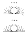
- Figures 5a, 5b, 6a and 6b schematically illustrate the forming flowers obtained in practicing a preferred embodiment of the method of the present invention.
- the forming flowers illustrated in Figure 5a, 5b, 6a are respectively obtained in the center forming processes of the center portion of the skelp in the initial and intermediate forming stages and the forming flower illustrated in Figure 6b is obtained in the forming process of the bent skelp in the stage of finish-forming or the fin pass forming.
- the three forming flowers illustrated in Figure 6b corresponds each to one of the caliber profiles of the roll stands in the case of the 3-stand fin pass forming.
- the skelp is formed by bending the center portion alone thereof to give a curvature of at least 80% of the final curvature of the finished pipe by use of a cage roll serving as a holding roll to successively hold and restrain the marginal edge portions of the skelp and a plurality of center-bend rolls successively installed along the progressing line of the forming and acting to restrain and bending the center portion of the skelp.
- the other portions of the skelp apart from the centerline in the transverse direction are intentionally left unformed including the marginal edge portions of the skelp each having an about one-third width of the skelp from the edge.
- This is a type of center forming by means of a cage roll in which the skelp is imparted with a U-shaped forming flower at the inlet of the fin pass forming stage corresponding to the finish forming.
- the above described forming process in the initial and intermediate forming steps is characteristic in the omission of the circular forming as is conventional in the prior art forming processes to form the side portions and edge portions of the rounded skelp.
- the center portion imparted with the specifed curvature should preferably cover from 25 to 50% of the overall width of the skelp in the transverse direction.
- the above mentioned step of center forming can be performed in several different ways without particular limitations.
- the bending work is started along the centerline of the skelp followed by the gradual increase of the width of the bent portion until the above mentioned percentage of the width has been covered to complete the center forming.
- the bending work is started along the lines remotest from the centerline within the above mentioned region for bending followed by the successive shift of the bending lines toward the centerline to complete the center forming.
- Figures 5a and 5b respectively illustrate the forming flowers in the former case and the latter case. It is of course possbile to combine these processes so that the forming flower may be as illustrated in Figure 6a.
- the first step of the inventive method is the center forming within a limited bending region on both sides of the centerline of the skelp leaving the portions of the skelp outside the bending region unformed.
- the types of the roll and apparatus for the above mentioned center forming of the skelp are not particularly limitative and rolls and apparatuses having various forms and structures can be used provided that the above described conditions of bending are satisfied.
- the skelp has a downhill pass line in practicing the inventive method, the chance of occurrence of the edge waves can further be decreased even when the thin wall thickness skelp is employed.
- the edge forming rolls used in the conventional cage forming and the inside rolls for working on the side portions of the skelp may no longer be required and the initial and intermediate forming stages, i.e. the cage roll forming, may be greatly shortened in comparison with the prior art methods.
- the initial and intermediate forming stages i.e. the cage roll forming
- occurrence of edge waves can be prevented because the skelp edges are continuously restrained in the cage roll forming process with further control of the path of width reduction of the skelp edges.
- the line length for the initial and intermediate forming stages can be as small as 15 to 20 times of the largest outer diameter of the pipe to be manufactured, that is, the line length can be only about 50 to 70% of that in the conventional cage forming process.
- the first fin pass roll (1 F) in the fin pass forming step serves to perform the following forming process. That is, the bending work on the side portions of the skelp under bending is intentionally limited such that the radius of curvature is not smaller than twice of the radius of the finally finished pipe and the transverse diameter, i.e. width, of the side portions of the rounded skelp is not smaller than the transverse diameter of the U-shaped skelp before the first fin pass roll.
- the edge portions of the skelp are bent and imparted with a curvature of at least 80% of the curvature in the finally finished pipe and over-bend forming is effected in the boundary regions between the side portion and edge portion of the rounded skelp and between the side portion and bottom portion of the rounded skelp to be imparted with a curvature larger than that in the finally finished pipe.
- the edge portions of the rounded skelp are readily formed by bending with a smaller fin pass reduction and the load in the fin pass forming is decreased.
- the edge portions of the rounded skelp are formed by bending to be imparted with a curvature of at least 80% of that in the finally finished pipe.
- the above mentioned curvature in the edge portions is essential in order to prevent peaking of the edges by welding leading to unacceptable bead cutting and defective upset welding.
- the forming by edge bending in the 2F and 3F to follow cannot be sufficient with the curvature of edge bending in 1F smaller than 80% resulting in deficiency in edge bending.
- Figures 7a and 7b are each a model illustration showing the state of the formed skelp and the forces acting on the rounded skelp in the first fin pass roll according to the inventive method and the prior art forming process, respectively. Assuming that the reduction force F is the same in these two processes, the reaction force f 3 is larger in the inventive method than in the prior art method as a result of the restrained bending on the side portion C of the rounded skelp.
- the boundary region B between the side portion C of the rounded skelp under restrained bending and the edge portion A of the rounded skelp is formed by overbending to be imparted with a curvature larger than that in the edge portion A of the rounded skelp so that the edge is inclined lower than in the prior art method and the fin angle OF of the first fin pass roll can be smaller. Therefore, the circumferential forced as a component force of the fin pass reduction force F is decreased and the component force f 2 in the radial direction is increased.
- the thickness increase at the edge is smaller as a result of the decrease of the component force f 1 in the circumferential direction while bending of the skelp edge portion can readily be performed as a result of the increase of the component force f 2 in the radial direction and the reaction force f 3 from the roll to produce an increased bending moment action on the edge portion.
- the first fin pass forming process according to the preferred embodiment of the invention has advantages of the smaller thickness increase at the edges and the decrease of the fin pass reduction force in comparison with the prior art forming method.
- first fin pass roll (1 F) is followed by the second fin pass roll (2F) and the third fin pass roll (3F) which serve to reduce mainly in the direction of decreasing the vertical diameter of the rounded skelp so that the side portions C of the rounded skelp under restrained bending in the above mentioned firstfin pass roll (1F) are formed by successively bulging out in thetransverse direction to effect forming of the rounded skelp in the direction of increasing the transverse diameter.
- This forming step by bulging out is a process in which works are successively performed for forming the side portions of the rounded skelp by bending and unbending of the boundary regions B between the side portion and edge portion of the rounded skelp having been formed by over-bending in the first fin pass roll (1F).
- Figure 8 is a schematic illustration showing the forming process after the above mentioned second fin pass roll.
- the bulge-out forming of the side portion of the rounded skelp in the second fin pass roll may be followed.
- the method of the present invention is applicable to the fin pass roll forming with any number of the stands. Further, the applicability of the inventive method is not limited to any division type, i.e. 2-roll type, 4-roll type and so on, of the fin pass rolls.
- Figure 9 is a diagram showing the paths of the projection of the rounded skelp in the fin pass forming process according to the inventive method.
- the edge distance (W 3F ) in the final fin pass roll can be larger owing to the gradual increase in the transverse diameter of the rounded skelp and the V-shape angle (6 " ) at the welding portion can be also be larger. Accordingly, the welding at the squeeze roll can be performed with stability to ensure high quality of the products.
- edge bend forming of the skelp in the initial forming stage to impart the skelp before the fin pass forming with a forming flower similar to that obtained in the combination of the edge bend forming and the center bend forming followed by the finish forming in the step of the fin pass forming according to the inventive method.
- This latter process is advantageous, in particular, in the forming of a skelp of a relatively large thickness with further improved formabilty of the edge in addition to the decrease of the load in the fin pass forming.
- the method of the present invention may be practiced by comprising the step of edge bend forming added to the initial and intermediate forming stages in the forming process.
- the step of the center forming by the cage roll forming in the initial and intermediate forming stages according to the inventive method can be undertaken only with the precondition of the fin pass forming step according to the inventive method.
- the cage roll forming mentioned in the above given description is not an only way for the process of center forming in the initial and intermediate forming stages according to the inventive method but any one of the known forming processes is applicable to the inventive method.
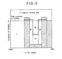
- Figure 11 is a roll map chart to illustrate an example of the forming process according to the inventive method.
- FIG 12 is a diagram to illustrate an example of the caliber profile of the fin pass roll with which the process of the fin pass forming can be performed according to the method of the invention.
- each fin pass roll along the line of the proceeding fin pass roll forming should have successively modified values for the form and size of the roll caliber profile R, and ⁇ , where i is 1 to 5, as well as the vertical diameter H, transverse diameter W, fin width W F and fin angle 8 F .
- the caliber profile may have successively decreasing values of H, W F , 8 F , R 3 and 8 3 and successively increasing values of W, R 2 , 8 2 , R 4 and 8 4 .
- the caliber profile of the squeeze roll used in the preferred embodiment of the inventive method is not limited to a true circularity but it is also possible to utilize a polygonal caliber profile of the squeeze roll as is illustrated in Figure 12 with extension of the process of fin pass forming.
- the progress of the fin pass forming is moderated to retain the side portions of the rounded skelp under the restrained bending as such in the squeeze roll forming or the folling pull-out roll forming and the works on these portions are left to the sizer forming in the succeeding steps.
- the applicability of the forming process according to the inventive method is not subject to the limitation by the dimensions of the skelp but the inventive method may be applicable to the manufacture of electric resistance welded steel pipes of any desired dimensions including the diameter and wall thickess.
- the roll pressure in the fin pass forming was smaller according to the inventive method than in the prior art method to achieve a 50 to 70% decrease in the fin pass total reduction and a 35 to 50% decrease in the fin pass forming load.
- the thickness increase at the edge in the inventive method was 50% or smaller of the value in the prior art method so that the bead cutting on the inner surface could be stabilized and occurrence of unacceptable products could be prevented in respect of the cross sectional configuration due to the wall thickness increase at the marginal edges in the case of the thick skelp.
- Figure 13 is a graph showing the thickness increase at the edge portion in the preparation of the above described 24-inch pipes making comparison between the prior art method and inventive method. It is clear that the inventive method is effective to greatly decrease the thickness increase at the edge portion.
- the inventive method was effective in decreasing the open length at the front and rear ends of the skelp due to incomplete forming by about 50% and the acceptable products could be increased by about 5% in the ultrasonic inspection of the welded portions.
- spring-back of the rounded skelp could be decreased in the inventive method as a consequence of the improvement in the direction of the residual bending moement within the circumferential direction of the rounded skelp after the fin pass roll forming and the finished welded pipes could have very exact forms and dimensions.
- the method of the present invention has a wide versatility or applicability to the manufacturing processes for the welded steel pipes which can hardly be manufactured by the prior art forming methods for the reasons in the formability of the skelp and the strength of the forming facilities.
- the inventive method was reproducibly successful in the manufacture of welded steel pipes of 26 inchesx6.0 mm (X60) corresponding to the value oft/D (wall thickness/outer diameter) of 0.9% and 20 inchesx22 mm (X52) corresponding to the t/D value of 4.3% while welded steel pipes of such grades can be manufactured in the prior art method with great difficulties.
- the number of stock rolls in the inventive method may be as small as 43 while the prior art method requires 87.
- the edge forming roll and the inside forming roll indispensable in the prior art method can be omitted in the inventive method.
- the line length of the initial and intermediate forming stages can be as short as 15 to 20 times of the maximum outer diameter D m which is only 50 to 70% of the line length in the prior art forming process. Further, the time required for the replacement of the rolls and adjustment of the rolls can be decreased by about 40% in comparison with the prior art method in the change of the pipe diameter under manufacturing.
- the improvements provided by the above described novel method include stabilization and easiness of the rounded skelp forming in the initial and intermediate forming stages, shortened line length as a result of the decreased number of the forming rolls, enlarged versatility of the rolls for a combined use and decrease of the length of time taken for the adjustment and replacement of the rolls.
- the edge portion of the rounded skelp can be formed by bending in the fin pass forming with prevention of the increase of wall thickness in the edge portions and the load in the forming can be reduced due to the decrease fin pass reduction.
- the adjustment of reduction can be omitted in the grade change for the thickness of the skelp.
- the V-shape at the welded portion can be increased and the residual stress of the rounded skelp in the circumferential direction can be decreased as a result of the increase in the fin width at the rearmost fin pass roll consequently with an increased yield rate and improvements in the form and size of the pipes and quality of the welded portion of the final products manufactured with increased operating rate of the mill and decreased investment for the facilities and cost for the rolls as well as an enlarged range of the manufacturable grades of the products in a mill.
Landscapes
- Engineering & Computer Science (AREA)
- Mechanical Engineering (AREA)
- Bending Of Plates, Rods, And Pipes (AREA)
Applications Claiming Priority (3)
| Application Number | Priority Date | Filing Date | Title |
|---|---|---|---|
| JP58131938A JPS6024220A (ja) | 1983-07-21 | 1983-07-21 | 電縫鋼管の成形方法 |
| JP131938/83 | 1983-07-21 | ||
| IN376CA1989 IN172377B (enExample) | 1983-07-21 | 1989-05-15 |
Publications (3)
| Publication Number | Publication Date |
|---|---|
| EP0133245A2 EP0133245A2 (en) | 1985-02-20 |
| EP0133245A3 EP0133245A3 (en) | 1985-07-24 |
| EP0133245B1 true EP0133245B1 (en) | 1988-09-28 |
Family
ID=26324269
Family Applications (1)
| Application Number | Title | Priority Date | Filing Date |
|---|---|---|---|
| EP84108542A Expired EP0133245B1 (en) | 1983-07-21 | 1984-07-19 | A method for forming an electric resistance welded steel pipe |
Country Status (3)
| Country | Link |
|---|---|
| EP (1) | EP0133245B1 (enExample) |
| JP (1) | JPS6024220A (enExample) |
| IN (1) | IN172377B (enExample) |
Families Citing this family (2)
| Publication number | Priority date | Publication date | Assignee | Title |
|---|---|---|---|---|
| JPS6142428A (ja) * | 1984-08-07 | 1986-02-28 | Ishikawajima Harima Heavy Ind Co Ltd | 管成形方法及び装置 |
| JP6090212B2 (ja) * | 2014-03-07 | 2017-03-08 | Jfeスチール株式会社 | 厚肉電縫管の製造方法 |
Family Cites Families (6)
| Publication number | Priority date | Publication date | Assignee | Title |
|---|---|---|---|---|
| US2234450A (en) * | 1938-10-14 | 1941-03-11 | Bundy Tubing Co | Method for making tubes |
| US2563214A (en) * | 1946-02-14 | 1951-08-07 | Clyde R Croson | Pipe-making machine |
| US2948324A (en) * | 1955-10-18 | 1960-08-09 | Pirelli General Cable Works | Manufacture of tubing and tubular sheathing |
| US2998047A (en) * | 1958-03-05 | 1961-08-29 | Bundy Tubing Co | Method of making tube from strip metal stock |
| JPS52151135U (enExample) * | 1976-05-14 | 1977-11-16 | ||
| JPS54145361A (en) * | 1978-05-02 | 1979-11-13 | Nippon Steel Corp | Roller forming cylindrical pipe |
-
1983
- 1983-07-21 JP JP58131938A patent/JPS6024220A/ja active Granted
-
1984
- 1984-07-19 EP EP84108542A patent/EP0133245B1/en not_active Expired
-
1989
- 1989-05-15 IN IN376CA1989 patent/IN172377B/en unknown
Also Published As
| Publication number | Publication date |
|---|---|
| EP0133245A3 (en) | 1985-07-24 |
| EP0133245A2 (en) | 1985-02-20 |
| IN172377B (enExample) | 1993-07-10 |
| JPS6024220A (ja) | 1985-02-06 |
| JPH0372366B2 (enExample) | 1991-11-18 |
Similar Documents
| Publication | Publication Date | Title |
|---|---|---|
| US4460118A (en) | Method for forming electric welded pipe | |
| CN100540170C (zh) | 方管成形用轧辊、方管的轧辊成形方法及成形装置 | |
| US4590781A (en) | Method for forming an electric resistance welded steel pipe | |
| EP0133245B1 (en) | A method for forming an electric resistance welded steel pipe | |
| EP0059957B1 (en) | Method of forming electric welded steel tube | |
| CA1239778A (en) | Method for forming an electric resistance welded steel pipe | |
| JPH06198337A (ja) | 溶接鋼管矯正方法 | |
| JP2008194744A (ja) | 電縫鋼管の矯正方法 | |
| JPH021564B2 (enExample) | ||
| JPS63286220A (ja) | 電縫管の製造方法 | |
| JP2994202B2 (ja) | 真円度の優れた電縫鋼管の製造方法 | |
| JPS61115685A (ja) | 電縫鋼管の製造方法 | |
| RU2763696C1 (ru) | Способ изготовления электросварных прямошовных труб | |
| JPH0371204B2 (enExample) | ||
| RU2040988C1 (ru) | Способ изготовления сварных прямошовных труб | |
| JPH0442097B2 (enExample) | ||
| JP3119821B2 (ja) | 電縫鋼管製造時におけるロール成形方法及びブレークダウンロール群 | |
| JP3946534B2 (ja) | 外径形状に優れた電縫鋼管の製造方法 | |
| JPH08243646A (ja) | 角鋼管の製造方法 | |
| JPS63281713A (ja) | 電縫鋼管の製造方法 | |
| JP3610824B2 (ja) | 薄肉溶接管の製造方法 | |
| JPS63165022A (ja) | 電縫鋼管の製造方法 | |
| GB2062503A (en) | Improvements in and relating to making wheel rims | |
| RU2040997C1 (ru) | Способ производства листовых гнутых профилей | |
| JPH06234020A (ja) | 電縫鋼管の製造方法 |
Legal Events
| Date | Code | Title | Description |
|---|---|---|---|
| PUAI | Public reference made under article 153(3) epc to a published international application that has entered the european phase |
Free format text: ORIGINAL CODE: 0009012 |
|
| AK | Designated contracting states |
Designated state(s): DE FR GB |
|
| PUAL | Search report despatched |
Free format text: ORIGINAL CODE: 0009013 |
|
| AK | Designated contracting states |
Designated state(s): DE FR GB |
|
| 17P | Request for examination filed |
Effective date: 19850911 |
|
| 17Q | First examination report despatched |
Effective date: 19860410 |
|
| GRAA | (expected) grant |
Free format text: ORIGINAL CODE: 0009210 |
|
| AK | Designated contracting states |
Kind code of ref document: B1 Designated state(s): DE FR GB |
|
| REF | Corresponds to: |
Ref document number: 3474264 Country of ref document: DE Date of ref document: 19881103 |
|
| ET | Fr: translation filed | ||
| PLBE | No opposition filed within time limit |
Free format text: ORIGINAL CODE: 0009261 |
|
| STAA | Information on the status of an ep patent application or granted ep patent |
Free format text: STATUS: NO OPPOSITION FILED WITHIN TIME LIMIT |
|
| 26N | No opposition filed | ||
| REG | Reference to a national code |
Ref country code: GB Ref legal event code: IF02 |
|
| PGFP | Annual fee paid to national office [announced via postgrant information from national office to epo] |
Ref country code: FR Payment date: 20030711 Year of fee payment: 20 |
|
| PGFP | Annual fee paid to national office [announced via postgrant information from national office to epo] |
Ref country code: GB Payment date: 20030716 Year of fee payment: 20 |
|
| PGFP | Annual fee paid to national office [announced via postgrant information from national office to epo] |
Ref country code: DE Payment date: 20030731 Year of fee payment: 20 |
|
| PG25 | Lapsed in a contracting state [announced via postgrant information from national office to epo] |
Ref country code: GB Free format text: LAPSE BECAUSE OF EXPIRATION OF PROTECTION Effective date: 20040718 |
|
| REG | Reference to a national code |
Ref country code: GB Ref legal event code: PE20 |