EP0132767A2 - Gripping head provided with two reciprocating fingers - Google Patents
Gripping head provided with two reciprocating fingers Download PDFInfo
- Publication number
- EP0132767A2 EP0132767A2 EP84108434A EP84108434A EP0132767A2 EP 0132767 A2 EP0132767 A2 EP 0132767A2 EP 84108434 A EP84108434 A EP 84108434A EP 84108434 A EP84108434 A EP 84108434A EP 0132767 A2 EP0132767 A2 EP 0132767A2
- Authority
- EP
- European Patent Office
- Prior art keywords
- gripping members
- gripping
- fingers
- gripper
- gripper according
- Prior art date
- Legal status (The legal status is an assumption and is not a legal conclusion. Google has not performed a legal analysis and makes no representation as to the accuracy of the status listed.)
- Withdrawn
Links
Images


Classifications
-
- B—PERFORMING OPERATIONS; TRANSPORTING
- B25—HAND TOOLS; PORTABLE POWER-DRIVEN TOOLS; MANIPULATORS
- B25J—MANIPULATORS; CHAMBERS PROVIDED WITH MANIPULATION DEVICES
- B25J15/00—Gripping heads and other end effectors
- B25J15/08—Gripping heads and other end effectors having finger members
- B25J15/10—Gripping heads and other end effectors having finger members with three or more finger members
- B25J15/106—Gripping heads and other end effectors having finger members with three or more finger members moving in parallel relationship
Definitions
- the invention relates to a gripper with two fingers movable relative to one another.
- Such grippers are used, for example, for industrial robots to handle various types of objects.
- two pliers-shaped, rigid fingers are provided, which grip and clamp the object from opposite sides. So that the object is securely held on the one hand between the fingers and on the other hand is not damaged during clamping, the shape of the fingers usually has to be adapted in a special way to the shape of the object.
- a particular gripper can therefore only be used for a narrowly limited class of objects. Although this disadvantage can be alleviated by the fact that the gripper surfaces of the fingers are padded with elastic material, this also does not lead to satisfactory results in the case of objects with a very different shape.
- the invention has for its object to provide a gripper of the type mentioned, which automatically adapts to the respective outer contour of the object to be gripped.
- At least one finger of the gripper comprises a number of gripping members which are movable relative to one another and which can be pressed against an object to be gripped with the aid of separate but interconnected hydraulic cylinders.
- the mutually movable gripping members on the one hand offer the possibility of adapting to the outer contour of the object, but on the other hand are all under the same pressure due to their hydraulic connection, so that the contact forces of the gripping members are evenly distributed over the entire surface of the object and damage by one strong local forces are avoided.
- the hydraulic connection can exist either for the gripping members of one finger or for the gripping members of both fingers, so that there is complete pressure compensation.
- these can either be formed by two mutually opposite groups of gripping members, which are arranged on a common holder, or by a divided holder, which forms two mutually movable jaws on which a group of gripping members is arranged in each case.
- the gripping members can be linearly displaceable lamellae or pins or swiveling gripping members of any shape.
- the hydraulic system serving to drive the gripping members preferably comprises a number of bores in the holder tion or the jaws in which pistons slide, which act in a suitable manner on the gripping members. These can be returned to the rest position by springs.
- the gripping movement of the gripping members can be in the closing direction, but possibly also in the spreading direction if, for example, a pot-shaped object is to be gripped from the inside.
- two pistons act on each gripping member in the opposite direction of movement, so that the gripping process can alternatively take place in the closing or opening direction.
- At least one gripping member from a group of gripping members can be synchronized with a corresponding gripping member of the second group, so that the opening and closing movement takes place symmetrically. In this way, the detected object arrives exactly in the middle position, so that, for example, it can be set down in a predetermined position.
- the remaining gripping members can freely adapt to the shape of the object in the manner described above.
- a gripper shown in FIGS. 1 and 2 comprises two identically constructed jaws 10, 12, which can be moved along guide rods 14 with the aid of a drive (not shown).
- the jaws 10, 12 each have a rectangular recess 16 in their mutually facing surfaces, which accommodates a set of lamellae 18 lying flat against one another.
- the slats 18 are each V-shaped on their edge facing the other cheek and form gripping members for gripping an object, not shown, located between the two sets of slats.
- Each of the lamellae 18 has two elongated holes 20, which each receive a rod 22 fastened to the jaw 10 or 12 and running across all the lamellae, and can thus be displaced with respect to the jaw in a limited area parallel to the guide rods 14.
- Fig. 1 the slats are shown in their fully retracted position in the jaws, while the fully extended position of the slats is indicated by dashed lines.
- Each of the lamellae has on its inner edge 24 facing the jaw two projections 26 arranged in the extension of the elongated holes 20, which protrude into cylindrical bores 28 of the jaw 10, 12.
- Each of the bores 28 receives a piston 32 provided with a sealing ring 30, which is biased towards the extension 26 by a spring 34 with a low spring constant.
- the sections of the bores 28 which receive the springs 34 are connected to one another by a chamber 36.
- the chamber 36 is connected via a tap hole 38 to a buffer chamber 42 delimited by two pistons 40.
- the pistons 40 are biased in the direction of the buffer chamber 42 by two springs 44, 46 with different spring constants.
- the springs 44, 46 are each supported on a plug 48 at the outer ends.
- the bore forming the buffer chamber 42 and receiving the pistons 40, the springs 44, 46 and the plugs 48 is formed in a block 50 which is detachable from the main body of the jaw 10, 12, so that the springs 34, 44, 46 after removal of the block 50 and the plug 48 replaced or by. the plugs can be tightened deeper.
- the block 50 is sealingly connected to the main body of the jaw, so that the Buffer chamber 42, the tap hole 38, the chamber 36 and the bores 28 form a closed cavity.
- This cavity is completely filled with a working fluid, for example a brake fluid.
- the jaws 10, 12 are moved towards one another.
- the jaws are moved, for example, with a drive, the driving force of which can be limited to a value at which there is no risk of damage to the object.
- the slats 18 are held by the springs 34 in the extended position shown in dashed lines in FIG. 1.
- the first fins strike the object, they are pushed back into the recess 16, and the pistons 32 assigned to these fins are pushed further into the bores 28 by the lugs 26.
- the springs 34 provide little resistance to this movement.
- the reduction in volume caused by the inward movement of the pistons is compensated for by compression of the likewise easily compressible spring 44 while displacing one of the pistons 40. If, during the further movement of the jaws 10, 12, the other lamellae 18 also gradually hit the object and, depending on the shape of the object, are pushed more or less far into the recess 16, the total volume of the bores 28 is reduced so much, that the spring 44 is fully compressed. As the jaws 10, 12 move further, the compression of the stronger spring 46 begins, and the fluid pressure in the hydraulic systems of the two jaws - and thus the resistance to the movement of the jaws 10, 12 - increases noticeably. If this resistance exceeds a predetermined threshold, the jaw drive is switched off, and the object is firmly and securely clamped between the plate sets.
- the lugs 26 of the lamellae have a rectangular cross section, while the bores 28 have a circular cross section.
- the bores 28 are staggered in several parallel rows.
- the lamellae 18 can be arranged directly next to one another, although their width is less than the diameter of the bores 28.
- the pistons 32 assigned to the same lamellae 18 have corresponding active surfaces, so that the hydraulic forces acting on them are the same and the slat is not tilted.
- the pistons 32 belonging to different fins can also have different active surfaces, so that the fins are pressed onto the object with different contact pressure.
- Different contact forces can also be achieved in that the bores assigned to a lamella are connected to one another by a channel instead of through the chamber 26 and are separated from the other bores 28 and that a separate buffer unit corresponding to the block 50 is provided for each pair of bores Springs 44,46 of different strength is provided.
- a buffer such as is formed by the buffer chamber 42, the pistons 40 and the springs 44, 46, has the advantage that the object can be gripped particularly softly and gently.
- a similar buffering effect can optionally also be included in the hydraulic systems Air bubbles can be achieved.
- the buffer can also be completely omitted, so that the H y drauliksystem comprises only the chamber 26 and the bores 28th
- the volume of the working fluid must be selected such that the slats 18 in the rest position take up a middle position between the extreme positions shown in FIG. 1, so that the volume reduction which occurs during the inward movement of a part of the slats due to an outward movement of the other slats can be compensated.
- the volume of the buffer chamber 42 can be changed with the aid of a piston which can be actuated from the outside or a screw-in spindle, so that the hydraulic pressure and thus the clamping force can be varied as required.
- the jaws do not have to be arranged so that they can be moved in parallel on guide rods. Rather, they can also be located on the tongues of a gripping pliers, which may also be a multi-joint pliers with a toggle mechanism.
- the available space will generally be an important consideration for the selection.
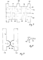
- FIGS. 3 and 4 While in the previously described embodiment the gripping members are arranged on two mutually movable jaws and are in turn movable with respect to the jaws, an embodiment will be described below with reference to FIGS. 3 and 4, in which two groups of gripping members against one another and with respect to one common bracket are movable.
- a holder 52 has, according to FIGS. 3 and 4, the shape of a cuboid block, on which two plates 54, 56 are fastened on two opposite sides, which in the example shown in FIG. 3 protrude the block 52 to the right and left and upwards .
- the plate 54 facing the viewer has been omitted for clarity.
- gripping members 58, 60, 62, 64 and 66 are mounted on both sides of the block 52. This storage takes place with the aid of axes 68, 70 which pivotally accommodate the gripping members and connect the plates 54, 56 to one another. It can be seen from FIG. 4 that the gripping members 58, 60, 62, 64 lie directly against one another in the lower region lying between the plates 54, 56, but are formed narrower in the upper region and have mutual distances.
- the gripping members 58, 60, 62, 64, 66 overall have the shape of narrow, flat strips. They are provided in the area of their free ends on the mutually facing sides with notches 72, 74 for grasping an object. In the lower area in FIG. 3, the gripping members have a chamfer, which is not described in any more detail, which leads to the gripping members assuming a slightly spread position when they bear against the block 52. In this position, the gripping members are prestressed by compression springs 76, 78, which are located in blind bores 80, 82 on the top of the block 52 and, on the other hand, support on lugs 84, 86 which extend inwards from the gripping members, that is to say in the direction of the respective other gripping member group.
- FIG. 3 the hydraulic drive of the gripping members is indicated in dashed lines in FIG. 3, which here also essentially corresponds to the principle described in connection with the first embodiment, but is designed differently in detail in terms of construction.
- a continuous bore 88 serving as a cylinder is provided between two opposite gripping members, in the example of FIG. 3 between gripping members 58 and 66, in which two pistons 90, 92 lie, the total length of which corresponds to that of the bore.
- the pistons have a truncated cone-shaped bevel 94.96 at the mutually abutting end.
- annular chamber In the area of the bevels 94, 96, an annular chamber, not shown, is formed in the bore 88, into which a branch channel 98 opens, which emanates from a common main channel 100, through which all the bores of the pairs of gripper members are supplied with hydraulic fluid will.
- the gripping process can also consist in a spreading movement in which, for example, a grip is made into the interior of a pot-shaped object.
- embodiments are considered that are double-acting and allow both gripping movements, as will be explained below using the example of FIGS. 5 to 7.
- FIG. 5 again shows a block 102, on which in this case four pairs of opposing gripping members are mounted, of which only the gripping members 104, 106 are shown in FIG. 5.
- the block 102 comprises a central and two outer, rectangular carrier plates 108, 110, 112, between the upper and lower edges of which cylinder plates 114, 116, 118, 120 are fastened, which, according to FIG. 6, form two essentially rectangular recesses 122, 124 together with the carrier plates.
- cylinder plates 114, 116, 118, 120 there are two bores 126, 128, 130, 132, 134, 136, 138, 140 which run perpendicular to the plane of the drawing in FIG. 6 and serve as cylinders of the hydraulic drive according to the invention.
- the carrier plate 112 is omitted in FIG. 5.
- axes 150, 152 are in Figure 5 shown.
- the gripping members 104, 106 have essentially semicircular projections 154, 156 on the sides facing one another, through which the axes 150, 152 pass.
- the gripping members 104, 106 shown in FIG. 5 serve only as carriers for the gripping fingers (not shown) or other gripping mechanisms which can be brought together or even spread during gripping. Bores 166, 168 are indicated for fastening such mechanisms.
- the pistons 158, 160, 162, 164 can act directly on the inner surfaces of the gripping members 104, 106, but in view of the pivoting movement carried out by the gripping members, this can lead to eccentric loads on the pistons and thus to signs of wear. Screws 170 according to FIG. 8 can therefore be screwed into the gripping members 104, 106, which have a spherical head 172 and a movable cap 174 placed thereon, each of which is in its position the face of the piston.
- FIG. 9 shows, using the example of a pair of gripping members 176, 178, one possibility for supplementing a gripper according to the invention, which can basically be used for all the described embodiments.
- the gripping members 176, 178 which correspond to the gripping members 104, 106 according to FIG. 5, have intermeshing teeth on the mutually facing, semicircular projections 180, 182, which lead to a synchronization of the movement of the gripping members.
- Such a pair of gripping members can be used if an object is to be brought into a predetermined, centered position when being gripped.
- this synchronization should only be used for individual pairs of grippers, such as the two outer pairs of grippers, so that the other pairs of grippers remain freely movable and can adapt to the shape of the gripped object.
Landscapes
- Engineering & Computer Science (AREA)
- Robotics (AREA)
- Mechanical Engineering (AREA)
- Manipulator (AREA)
Abstract
Description
Die Erfindung betrifft einen Greifer mit zwei gegeneinander beweglichen Fingern.The invention relates to a gripper with two fingers movable relative to one another.
Derartige Greifer werden beispielsweise für Industrieroboter zum Handhaben verschiedenartiger Gegenstände eingesetzt. üblicherweise sind zwei zangenförmige arbeitende, in sich starre Finger vorgesehen, die den Gegenstand von entgegengesetzten Seiten her erfassen und einspannen. Damit der Gegenstand einerseits sicher zwischen den Fingern festgehalten und andererseits beim Einspannen nicht beschädigt wird, muß die Form der Finger zumeist in besonderer Weise der Form des Gegenstandes angepaßt sein. Ein bestimmter Greifer ist daher jeweils nur für eine eng begrenzte Klasse von Gegenständen einsetzbar. Zwar läßt sich dieser Nachteil dadurch mildern, daß die Greiferflächen der Finger mit elastischem Material gepolstert werden, jedoch führt auch dies bei Gegenständen mit stark abweichender Form nicht zu befriedigenden Ergebnissen.Such grippers are used, for example, for industrial robots to handle various types of objects. Usually, two pliers-shaped, rigid fingers are provided, which grip and clamp the object from opposite sides. So that the object is securely held on the one hand between the fingers and on the other hand is not damaged during clamping, the shape of the fingers usually has to be adapted in a special way to the shape of the object. A particular gripper can therefore only be used for a narrowly limited class of objects. Although this disadvantage can be alleviated by the fact that the gripper surfaces of the fingers are padded with elastic material, this also does not lead to satisfactory results in the case of objects with a very different shape.
Auch Greifer mit auswechselbaren Fingern unterschiedlicher Form oder mit Fingern, deren Form im Hinblick auf einen zu erfassenden Gegenstand veränderbar ist, bieten nicht die Möglichkeit, Gegenstände unterschiedlicher Form in beliebiger Reihenfolge ohne Unterbrechung des Betriebs zu erfassen.Even grippers with interchangeable fingers of different shapes or with fingers whose shape can be changed with regard to an object to be gripped do not offer the possibility of gripping objects of different shapes in any order without interrupting operation.
Der Erfindung liegt die Aufgabe zugrunde, einen Greifer der eingangs genannten Art zu schaffen, der sich selbstätig der jeweiligen Außenkontur des zu greifenden Gegenstandes anpaßt.The invention has for its object to provide a gripper of the type mentioned, which automatically adapts to the respective outer contour of the object to be gripped.
Diese Aufgabe wird erfindungsgemäß dadurch gelöst, daß wenigstens ein Finger des Greifers eine Anzahl von relativ zueinander beweglichen Greifgliedern umfaßt, die mit Hilfe von gesonderten, jedoch untereinander verbundenen Hydraulikzylindern gegen einen zu greifenden Gegenstand andrückbar sind.This object is achieved in that at least one finger of the gripper comprises a number of gripping members which are movable relative to one another and which can be pressed against an object to be gripped with the aid of separate but interconnected hydraulic cylinders.
Die gegeneinander beweglichen Greifglieder bieten einerseits die Möglichkeit einer Anpassung an die äußere Kontur des Gegenstandes, stehen jedoch andererseits alle aufgrund ihrer hydraulischen Verbindung unter dem selben Druck, so daß sich die Anpreßkräfte der Greifglieder über die gesamte Oberfläche des Gegenstandes gleichmäßig verteilen und Beschädigungen durch eine zu starke örtliche Krafteinwirkung vermieden werden.The mutually movable gripping members on the one hand offer the possibility of adapting to the outer contour of the object, but on the other hand are all under the same pressure due to their hydraulic connection, so that the contact forces of the gripping members are evenly distributed over the entire surface of the object and damage by one strong local forces are avoided.
Die hydraulische Verbindung kann entweder für die Greifglieder eines Fingers oder auch für die Greifglieder beider Finger bestehen, so daß sich ein vollständiger Druckausgleich ergibt.The hydraulic connection can exist either for the gripping members of one finger or for the gripping members of both fingers, so that there is complete pressure compensation.
In Abhängigkeit von dem Ausmaß der erforderlichen öffnungs- und Schließbewegung der Finger können diese entweder gebildet werden durch zwei einander gegenüberliegende Gruppen von Greifgliedern, die auf einer gemeinsamen Halterung angeordnet sind, oder auch durch eine geteilte Halterung, die zwei gegeneinander bewegliche Backen bildet, auf denen jeweils eine Gruppe von Greifgliedern angeordnet ist.Depending on the extent of the required opening and closing movement of the fingers, these can either be formed by two mutually opposite groups of gripping members, which are arranged on a common holder, or by a divided holder, which forms two mutually movable jaws on which a group of gripping members is arranged in each case.
Die Greifglieder können linear verschiebbare Lamellen oder Stifte oder auch schwenkbare Greiforgane beliebiger Form sein.The gripping members can be linearly displaceable lamellae or pins or swiveling gripping members of any shape.
Das als Antrieb der Greifglieder dienende Hydrauliksystem umfaßt vorzugsweise eine Anzahl von Bohrungen in der Halterung oder den Backen, in denen Kolben gleiten, die in geeigneter Weise auf die Greifglieder einwirken. Diese können durch Federn in die Ruhestellung zurückgeführt werden. Die Greifbewegung der Greifglieder kann in Schließrichtung, ggf. aber auch in Spreizrichtung liegen, wenn etwa ein topfförmiger Gegenstand von innen her erfaßt werden soll. Bei einer besonders vielseitigen Ausführungsform wirken zwei Kolben auf jedes Greifglied in entgegengesetzter Bewegungsrichtung ein, so daß der Greifvorgang alternativ in Schließ- oder Öffnungsrichtung erfolgen kann.The hydraulic system serving to drive the gripping members preferably comprises a number of bores in the holder tion or the jaws in which pistons slide, which act in a suitable manner on the gripping members. These can be returned to the rest position by springs. The gripping movement of the gripping members can be in the closing direction, but possibly also in the spreading direction if, for example, a pot-shaped object is to be gripped from the inside. In a particularly versatile embodiment, two pistons act on each gripping member in the opposite direction of movement, so that the gripping process can alternatively take place in the closing or opening direction.
Wenigstens ein Greifglied aus einer Gruppe von Greifgliedern kann mit einem entsprechenden Greifglied der zweiten Gruppe synchronisiert sein, so daß die öffnungs-und Schließbewegung symmetrisch erfolgt. Auf diese Weise gelangt der erfaßte Gegenstand exakt in die Mittelposition, so daß etwa ein Absetzen in einer vorgegebenen Position möglich wird. Die übrigen Greifglieder können sich in der zuvor beschriebenen Weise frei der Form des Gegenstandes anpassen.At least one gripping member from a group of gripping members can be synchronized with a corresponding gripping member of the second group, so that the opening and closing movement takes place symmetrically. In this way, the detected object arrives exactly in the middle position, so that, for example, it can be set down in a predetermined position. The remaining gripping members can freely adapt to the shape of the object in the manner described above.
Im folgenden werden bevorzugte Ausführungsbeispiele der Erfindung anhand der beigefügten Zeichnung näher erläutert.Preferred exemplary embodiments of the invention are explained in more detail below with reference to the attached drawing.
- Fig. 1 ist ein schematischer Schnitt durch eine erste Ausführungsform eines erfindungsgemäßen Greifers;Fig. 1 is a schematic section through a first embodiment of a gripper according to the invention;
- Fig. 2 zeigt eine Greiferfläche in Draufsicht;Fig. 2 shows a gripper surface in plan view;
- Fig. 3 ist eine Ansicht einer zweiten Ausführungsform eines erfindungsgemäßen Greifers;3 is a view of a second embodiment of a gripper according to the invention;
- Fig. 4 ist eine Ansicht von links in Figur 3;Fig. 4 is a left view in Fig. 3;
- Fig. 5 ist eine Darstellung einer dritten Ausführungsform eines erfindungsgemäßen Greifers mit doppelt wirkendem Antrieb der Greifglieder;5 is an illustration of a third embodiment of a gripper according to the invention with double-acting drive of the gripping members;
- Fig. 6 ist eine Ansicht der Halterung der Greifglieder von links in Figur 5;Figure 6 is a left side view of the gripping member support in Figure 5;
- Fig. 7 ist eine Draufsicht zu Figur 6;Figure 7 is a top view of Figure 6;
- Fig. 8 zeigt eine Einzelheit zu Figur 5;Figure 8 shows a detail of Figure 5;
- Fig. 9 veranschaulicht zwei in ihrer Bewegung synchronisierte Greifglieder.9 illustrates two gripping members synchronized in their movement.
Ein in Figur 1 und 2 gezeigter Greifer umfaßt zwei identisch aufgebaute Backen 10,12, die mit Hilfe eines nicht gezeigten Antriebs entlang Führungsstangen 14 verschiebbar sind. Die Backen 10,12 weisen in ihren einander zugewandten Oberflächen je eine rechteckige Aussparung 16 auf, die einen Satz flach aneinander anliegender Lamellen 18 aufnimmt. Die Lamellen 18 sind jeweils an ihrer der anderen Backe zugewandten Kante V-förmig ausgenommen und bilden Greifglieder zu Erfassen eines nicht gezeigten, zwischen den beiden Lamellen-Sätzen befindlichen Gegenstandes.A gripper shown in FIGS. 1 and 2 comprises two identically constructed
Jede der Lamellen 18 weist zwei Langlöcher 20 auf, die jeweils eine an der Backe 10 bzw. 12 befestigte, quer durch sämtliche Lamellen laufende Stange 22 aufnehmen, und sind somit in bezug auf die Backe in einem begrenzten Bereich parallel zu den Führungsstangen 14 verschiebbar. In Fig. 1 sind die Lamellen in ihrer vollständig in die Backen zurückgezogenen Stellung dargestellt, während die vollständig ausgefahrene Stellung der Lamellen durch gestrichelte Linien angedeutet ist.Each of the
Jede der Lamellen weist an ihrer der Backe zugewandten inneren Kante 24 zwei in Verlängerung der Langlöcher 20 angeordnete Ansätze 26 auf, die in zylindrische Bohrungen 28 der Backe 10,12 hineinragen.Each of the lamellae has on its
Jede der Bohrungen 28 nimmt einen mit einem Dichtring 30 versehenen Kolben 32 auf, der durch eine Feder 34 mit geringer Federkonstante in Richtung auf den Ansatz 26 vorgespannt wird. Die die Federn 34 aufnehmenden Abschnitte der Bohrungen 28 sind durch eine Kammer 36 miteinander verbunden. Die Kammer 36 steht über eine Stichbohrung 38 mit einer durch zwei Kolben 40 begrenzten Pufferkammer 42 in Verbindung. Die Kolben 40 werden durch zwei Federn 44,46 mit unterschiedlichen Federkonstanten in Richtung auf die Pufferkammer 42 vorgespannt. Die Federn 44,46 sind an den äußeren Enden jeweils an einem Stopfen 48 abgestützt. Die die Pufferkammer 42 bildende und die Kolben 40, die Federn 44,46 und die Stopfen 48 aufnehmende Bohrung ist in einem von dem Hauptkörper der Backe 10,12 lösbaren Block 50 ausgebildet, so daß die Federn 34,44,46 nach Entfernen des Blockes 50 und der Stopfen 48 ausgewechselt bzw. durch . tieferes Einschrauben der Stopfen nachgespannt werden können.Each of the
In der montierten Stellung ist der Block 50 dichtend mit dem Hauptkörper der Backe verbunden, so daß die Pufferkammer 42, die Stichbohrung 38, die Kammer 36 und die Bohrungen 28 einen geschlossenen Hohlraum bilden. Dieser Hohlraum ist vollständig mit einem Arbeitsfluid, beispielsweise einer Bremsflüssigkeit ausgefüllt.In the assembled position, the
Wenn ein zwischen den Backen 10,12 befindlicher Gegenstand von dem Greifer erfaßt werden soll, so werden die Backen 10,12 aufeinander zu bewegt. Die Bewegung der Backen erfolgt beispielsweise mit einem Antrieb, dessen Antriebskraft auf einen Wert begrenzbar ist, bei dem keine Gefahr einer Beschädigung des Gegenstandes besteht. Die Lamellen 18 werden durch die Federn 34 in der in Fig. 1 gestrichelt dargestellten ausgefahrenen Stellung gehalten. Wenn die ersten Lamellen an dem Gegenstand anschlagen, so werden sie in die Aussparung 16 zurückgedrückt, und die diesen Lamellen zugeordneten Kolben 32 werden durch die Ansätze 26 weiter in die Bohrungen 28 hineingedrückt. Die Federn 34 setzen dieser Bewegung nur einen geringen Widerstand entgegen. Die durch die Einwärtsbewegung der Kolben bewirkte Volumenverringerung wird durch eine Kompression der ebenfalls leicht komprimierbaren Feder 44 unter Verschiebung eines der Kolben 40 ausgeglichen. Wenn bei der weiteren Bewegung der Backen 10,12 nach und nach auch die übrigen Lamellen 18 an dem Gegenstand anschlagen und je nach der Form des Gegenstandes mehr oder weniger weit in die Aussparung 16 zurückgedrückt werden, verringert sich das Gesamtvolumen der Bohrungen 28 so weit, daß die Feder 44 vollständig komprimiert wird. Bei der weiteren Bewegung der Backen 10,12 setzt die Kompression der stärkeren Feder 46 ein, und der Fluiddruck in den Hydrauliksystemen der beiden Backen - und damit der der Bewegung der Backen 10,12 entgegenwirkende Widerstand - nimmt spürbar zu. Wenn dieser Widerstand einen vorgegebenen Schwellenwert übersteigt, wird der Backen-Antrieb abgeschaltet, und der Gegenstand ist fest und sicher zwischen den Lamellen-Sätzen eingespannt.If an object located between the
Wie in Fig. 2 zu erkennen ist, weisen die Ansätze 26 der Lamellen einen rechteckigen Querschnitt auf, während die Bohrungen 28 einen kreisförmigen Querschnitt aufweisen. Die Bohrungen 28 sind in mehreren parallelen Reihen versetzt angeordnet. Auf diese Weise können die Lamellen 18 unmittelbar nebeneinander liegend angeordnet werden, obgleich ihre Breite geringer ist als der Durchmesser der Bohrungen 28. Die der selben Lamelle 18 zugeordneten Kolben 32 weisen übereinstimmende Wirkflächen auf, so daß die auf sie wirkenden hydraulischen Kräfte gleich groß sind und die Lamelle nicht verkantet. Die zu verschiedenen Lamellen gehörenden Kolben 32 können dagegen abweichend von dem gezeigten Ausführungsbeispiel auch unterschiedliche Wirkflächen aufweisen, so daß die Lamellen mit unterschiedlicher Anpreßkraft an den Gegenstand angedrückt werden.As can be seen in FIG. 2, the
Unterschiedliche Anpreßkräfte können auch dadurch erreicht werden, daß die einer Lamelle zugeordneten Bohrungen statt durch die Kammer 26 lediglich durch einen Kanal miteinander verbunden und von den übrigen Bohrungen 28 getrennt sind und daß für jedes Bohrungs-Paar eine eigene Puffer-Einheit entsprechend dem Block 50 mit Federn 44,46 unterschiedlicher Stärke vorgesehen ist.Different contact forces can also be achieved in that the bores assigned to a lamella are connected to one another by a channel instead of through the
Ein Puffer, wie er beispielsweise durch die Pufferkammer 42, die Kolben 40 und die Federn 44,46 gebildet wird, hat den Vorteil, daß der Gegenstand durch die Lamellen besonders weich und schonend erfaßt werden kann. Eine ähnliche Pufferungswirkung kann wahlweise auch durch in den Hydrauliksystemen eingeschlossene Luftblasen erzielt werden.A buffer, such as is formed by the
In einer abgewandelten Ausführungsform kann der Puffer auch vollständig fortgelassen werden, so daß das Hy-drauliksystem lediglich die Kammer 26 und die Bohrungen 28 umfaßt. In diesem Fall muß allerdings das Volumen des Arbeitsfluids derart gewählt werden, daß die Lamellen 18 in der Ruhestellung eine mittlere Position zwischen den in Fig. 1 gezeigten Extremstellungen aufnehmen, damit die bei der Einwärtsbewegung eines Teils der Lamellen eintretende Volumenverringerung durch eine Auswärtsbewegung der anderen Lamellen ausgeglichen werden kann.In a modified embodiment, the buffer can also be completely omitted, so that the H y drauliksystem comprises only the
Gemäß einer weiteren Abwandlung des beschriebenen Ausführungsbeispiels ist das Volumen der Pufferkammer 42 mit Hilfe eines von außen betätigbaren Kolbens oder einer einschraubbaren Spindel veränderbar, so daß der Hydraulikdruck und damit die Spannkraft nach Bedarf variiert werden kann.According to a further modification of the described embodiment, the volume of the
Die Backen müssen nicht parallelverschiebbar auf Führungsstangen angeordnet sein. Vielmehr können sie sich auch auf den Zungen einer Greifzange befinden, bei der es sich ggf. auch um eine Mehrgelenkzange mit Kniehebelmechanik handeln kann. Wesentlicher Gesichtspunkt für die Auswahl werden in der Regel die gegebenen Platzverhältnisse sein.The jaws do not have to be arranged so that they can be moved in parallel on guide rods. Rather, they can also be located on the tongues of a gripping pliers, which may also be a multi-joint pliers with a toggle mechanism. The available space will generally be an important consideration for the selection.
Während bei der zuvor beschriebenen Ausführungsform die Greifglieder auf zwei gegeneinander beweglichen Backen angeordnet und zudem ihrerseits in Bezug auf die Backen beweglich sind, soll anschließend anhand von Figur 3 und 4 eine Ausführungsform beschrieben werden, bei der zwei Gruppen von Greifgliedern gegeneinander und in Bezug auf eine gemeinsame Halterung beweglich sind. Eine derartige Halterung 52 weist gemäß Figur 3 und 4 die Form eines quaderförmigen Blockes auf, an dem an zwei gegenüberliegenden Seiten zwei Platten 54,56 befestigt sind, die in dem in Figur 3 gezeigten Beispiel den Block 52 nach rechts und links sowie nach oben überragen. In Figur 3 ist die dem Betrachter zugewandte Platte 54 zur Verdeutlichung fortgelassen worden. Zwischen den beiden Platten 54,56 sind auf beiden Seiten des Blockes 52 jeweils vier Greifglieder 58,60,62,64 bzw. 66 gelagert. Diese Lagerung erfolgt mit Hilfe von Achsen 68,70, die die Greifglieder schwenkbar aufnehmen und die Platten 54,56 miteinander verbinden. Aus Figur 4 geht hervor, daß die Greifglieder 58,60,62,64 in dem zwischen den Platten 54,56 liegenden unteren Bereich unmittelbar gegeneinander anliegen, im oberen Bereich dagegen schmaler ausgebildet sind und gegenseitige Abstände aufweisen.While in the previously described embodiment the gripping members are arranged on two mutually movable jaws and are in turn movable with respect to the jaws, an embodiment will be described below with reference to FIGS. 3 and 4, in which two groups of gripping members against one another and with respect to one common bracket are movable. Such a
Die Greifglieder 58,60,62,64,66 weisen insgesamt die Form schmaler, flacher Streifen auf. Sie sind im Bereich ihrer freien Enden auf den einander zugewandten Seiten mit Einkerbungen 72,74 zum Erfassen eines Gegenstandes versehen. Im unteren Bereich in Figur 3 weisen die Greifglieder eine nicht näher bezeichnete Abschrägung auf, die dazu führt, daß die Greifglieder bei einem Anliegen gegen den Block 52 eine leicht gespreizte Stellung einnehmen. In diese Stellung sind die Greifglieder vorgespannt durch Druckfedern 76,78, die sich einerseits in Sackbohrungen 80,82 auf der Oberseite des Blocks 52 und andererseits an Ansätzen 84,86 abstützen, die von den Greifgliedern nach innen, also in Richtung der jeweils anderen Greifglieder-Gruppe ausgehen.The gripping
Im unteren Bereich des Blocks 52 ist in Figur 3 der hydraulische Antrieb der Greifglieder gestrichelt angedeutet, der auch hier im wesentlichen dem in Verbindung mit der ersten Ausführungsform geschilderten Prinzip entspricht, konstruktiv jedoch im einzelnen anders ausgeführt ist. In dem Block 52 ist jeweils zwischen zwei einander gegenüberliegenden Greifgliedern, im Beispiel der Figur 3 zwischen den Greifgliedern 58 und 66, eine durchgehende, als Zylinder dienende Bohrung 88 vorgesehen, in der zwei Kolben 90,92 liegen, deren Gesamtlänge derjenigen der Bohrung entspricht. Die Kolben weisen an den gegeneinander anliegenden Ende eine kegelstumpfförmige Abschrägung 94,96 auf. Im Bereich der Abschrägungen 94,96 entsteht somit in der Bohrung 88 eine ringförmige, im Querschnitt dreieckige, nicht bezeichnete Kammer, in die ein Stichkanal 98 einmündet, der von einem gemeinsamen Hauptkanal 100 ausgeht, durch den alle Bohrungen der Greifglieder-Paare mit Hydraulikfluid versorgt werden.In the lower area of
Wenn durch den Hauptkanal 100 und die einzelnen Stichkanäle 98 Hydraulikfluid in die Bohrungen 88 gelangt, werden die Kolben 90,92 auseinandergetrieben, so daß die Greifglieder 58,66 an ihren freien Enden zusammengedrückt werden, wie es bereits für das erste Ausführungsbeispiel beschrieben wurde. Wenn ein Greifglied oder Greifglieder-Paar den zu erfassenden Gegenstand berührt, bleibt es stehen, während das Hydraulikfluid in diejenigen Bohrungen 88 ausweicht, deren zugehörige Greifglieder den Gegenstand noch nicht erfaßt haben.When hydraulic fluid enters the
Während bei den zuvor beschriebenen Ausführungsformen die Greifglieder beim Erfassen eines Gegenstandes zusammengeführt werden, kann der Greifvorgang auch in einer Spreizbewegung bestehen, bei der beispielsweise in das Innere eines topfförmigen Gegenstandes hineingegriffen wird. Darüber hinaus kommen Ausführungsformen in Betracht, die doppelt wirkend ausgebildet sind und beide Greifbewegungen ermöglichen, wie anschließend am Beispiel von Figur 5 bis 7 erläutert werden soll.While in the previously described embodiments the gripping members are brought together when grasping an object, the gripping process can also consist in a spreading movement in which, for example, a grip is made into the interior of a pot-shaped object. In addition, embodiments are considered that are double-acting and allow both gripping movements, as will be explained below using the example of FIGS. 5 to 7.
Figur 5 zeigt wiederum einen Block 102, an dem in diesem Falle vier Paare von gegenüberliegenden Greifgliedern gelagert sind, von denen in Figur 5 nur die Greifglieder 104,106 gezeigt sind. Zunächst soll anhand von Figur 6 und 7 die Form des Blockes 102 erläutert werden, der in Figur 6 in einer Ansicht von links in Figur 5 und in Figur 7 in einer zugehörigen Draufsicht gezeigt ist. Der Block 102 umfaßt eine mittlere und zwei äußere, rechteckige Trägerplatten 108,110,112, zwischen deren oberem und unterem Rand Zylinderplatten 114,116,118,120 befestigt sind, die gemäß Figur 6 zusammen mit den Trägerplatten zwei im wesentlichen quaderförmige Ausnehmungen 122,124 bilden. In den Zylinderplatten 114,116,118,120 befinden sich jeweils zwei senkrecht zur Zeichenebene in Figur 6 verlaufende, als Zylinder des erfindungsgemäßen Hydraulikantriebes dienende Bohrungen 126,128,130,132,134,136,138, 140. Alle Bohrungen sind untereinander mit einem nicht gezeigten Zufuhrsystem für Hydraulikfluid mit Hilfe von quer zu den Bohrungen verlaufenden Zufuhrbohrungen 142,144 verbunden. Die Trägerplatte 112 ist in Figur 5 fortgelassen.FIG. 5 again shows a
Schließlich befinden sich in mittlerer Höhe der Trägerplatten 108,110,112, zwei miteinander fluchtende Bohrungen 146,148, die zur Aufnahme von Achsen als Lagerung für die Greifglieder dienen. Diese Achsen 150,152 sind in Figur 5 gezeigt. Die Greifglieder 104,106 weisen auf den einander zugewandten Seiten im wesentlichen halbkreisförmige Ansätze 154,156, die von den Achsen 150,152 durchlaufen werden.Finally, in the middle height of the
In Figur 5 sind im übrigen die bereits erwähnten Bohrungen 126,128,130,132,134,136,138,140 gestrichelt angedeutet, von denen in Figur 5 lediglich die Bohrungen 132,140 sichtbar sind. In den Bohrungen befinden sich wiederum zylindrische Kolben 158,160,162,164 mit kegelstumpfförmig abgeschrägten, nicht näher bezeichneten inneren Enden, zwischen denen die in Figur 6 dargestellten Zufuhrbohrungen 142,144 für das Hydraulikfluid münden. Die Kolben können somit aus den zugehörigen Bohrungen herausgedrückt werden und die Greifglieder 104,106 in Uhrzeigerrichtung oder gegen Uhrzeigerrichtung schwenken, je nach dem, ob die unteren oder oberen Bohrungen des Hydrauliksystems in Figur 5 mit Hydraulikfluid versorgt werden.5, the previously mentioned
Die in Figur 5 dargestellten Greifglieder 104,106 dienen lediglich als Träger für die nicht gezeigten Greiffinger oder sonstige Greifmechanismen, die beim Greifen zusammengeführt oder auch gespreizt werden können. Zur Befestigung derartiger Mechanismen sind Bohrungen 166,168 angedeutet.The gripping
Die Kolben 158,160,162,164 können unmittelbar auf die Innenflächen der Greifglieder 104,106 einwirken, jedoch kann dies angesichts der von den Greifgliedern durchgeführten Schwenkbewegung zu exzentrischen Belastungen der Kolben und damit zu Verschleißerscheinungen führen. In die Greifglieder 104,106 können daher Schrauben 170 gemäß Figur 8 eingedreht werden, die einen kugelförmigen Kopf 172 und eine auf diesen aufgesetzte, bewegliche Kappe 174 aufweisen, die sich jeweils in ihrer Position der Stirnfläche des Kolbens anpaßt.The
Figur 9 zeigt am Beispiel eines Paares von Greifgliedern 176,178 eine Möglichkeit zur Ergänzung eines erfindungsgemäßen Greifers, die grundsätzlich für alle beschriebenen Ausführungsformen anwendbar ist. In diesem Falle weisen die Greifglieder 176,178, die den Greifgliedern 104,106 gemäß Figur 5 entsprechen, auf den einander zugewandten, halbkreisförmigen Ansätzen 180,182 miteinander kämmende Verzahnungen auf, die zu einer Synchronisierung der Bewegung der Greifglieder führen. Ein derartiges Greifgliederpaar kann eingesetzt werden, wenn ein Gegenstand beim Erfassen in eine vorgegebene, zentrierte Position gebracht werden soll. Diese Synchronisation sollte jedoch nur für einzelne Greifgliederpaare, etwa die beiden äußeren Greifgliederpaare angewendet werden, so daß die übrigen Greifgliederpaare frei beweglich bleiben und sich der Form des ergriffenen Gegenstandes anpassen können.FIG. 9 shows, using the example of a pair of gripping
Claims (11)
Applications Claiming Priority (2)
| Application Number | Priority Date | Filing Date | Title |
|---|---|---|---|
| DE19833327060 DE3327060A1 (en) | 1983-07-27 | 1983-07-27 | GRIPPER WITH TWO MOVING JAWS |
| DE3327060 | 1983-07-27 |
Publications (2)
| Publication Number | Publication Date |
|---|---|
| EP0132767A2 true EP0132767A2 (en) | 1985-02-13 |
| EP0132767A3 EP0132767A3 (en) | 1986-04-02 |
Family
ID=6205045
Family Applications (1)
| Application Number | Title | Priority Date | Filing Date |
|---|---|---|---|
| EP84108434A Withdrawn EP0132767A3 (en) | 1983-07-27 | 1984-07-17 | Gripping head provided with two reciprocating fingers |
Country Status (2)
| Country | Link |
|---|---|
| EP (1) | EP0132767A3 (en) |
| DE (1) | DE3327060A1 (en) |
Cited By (1)
| Publication number | Priority date | Publication date | Assignee | Title |
|---|---|---|---|---|
| BE1019328A3 (en) * | 2009-05-14 | 2012-06-05 | Zahoransky Ag | PREVENTION CLIP. |
Families Citing this family (5)
| Publication number | Priority date | Publication date | Assignee | Title |
|---|---|---|---|---|
| ATE163876T1 (en) * | 1989-12-19 | 1998-03-15 | Amada Co Ltd | QUICK COUPLING DEVICE FOR A TOOL HEAD OF A MANIPULATOR |
| DE4339102A1 (en) * | 1992-11-26 | 1994-06-01 | Friedhelm Prof Dipl Ing Sehrt | Mechanical handling apparatus for hot, corrosive and radiative objects - has holding pins held in guide plate elastically deformed to match contour region of object to be handling |
| DE19531927C2 (en) * | 1995-08-16 | 1998-09-17 | Mannesmann Ag | Device for gripping and transporting piece goods, in particular containers |
| US5718531A (en) * | 1996-01-22 | 1998-02-17 | Lockheed Martin Corporation | Low shock release device |
| JP2989557B2 (en) * | 1996-12-06 | 1999-12-13 | 株式会社椿本チエイン | Article gripping device |
Citations (5)
| Publication number | Priority date | Publication date | Assignee | Title |
|---|---|---|---|---|
| SU210348A1 (en) * | Е. К. Соркин | LEVER CAPTURE FOR PIECE CARGOES | ||
| GB1332796A (en) * | 1970-08-24 | 1973-10-03 | Unigrip Mfg Co Ltd | Work piece supporting a holding device |
| JPS51126668A (en) * | 1975-04-25 | 1976-11-04 | Anritsu Corp | Robot handling means |
| DE2823584A1 (en) * | 1978-05-30 | 1979-12-06 | Pfaff Ind Masch | INDUSTRIAL ROBOT WITH A GRIPPING DEVICE |
| EP0020002A1 (en) * | 1979-05-22 | 1980-12-10 | The Marconi Company Limited | Manipulator mechanisms |
Family Cites Families (1)
| Publication number | Priority date | Publication date | Assignee | Title |
|---|---|---|---|---|
| SU210348A (en) * |
-
1983
- 1983-07-27 DE DE19833327060 patent/DE3327060A1/en not_active Withdrawn
-
1984
- 1984-07-17 EP EP84108434A patent/EP0132767A3/en not_active Withdrawn
Patent Citations (5)
| Publication number | Priority date | Publication date | Assignee | Title |
|---|---|---|---|---|
| SU210348A1 (en) * | Е. К. Соркин | LEVER CAPTURE FOR PIECE CARGOES | ||
| GB1332796A (en) * | 1970-08-24 | 1973-10-03 | Unigrip Mfg Co Ltd | Work piece supporting a holding device |
| JPS51126668A (en) * | 1975-04-25 | 1976-11-04 | Anritsu Corp | Robot handling means |
| DE2823584A1 (en) * | 1978-05-30 | 1979-12-06 | Pfaff Ind Masch | INDUSTRIAL ROBOT WITH A GRIPPING DEVICE |
| EP0020002A1 (en) * | 1979-05-22 | 1980-12-10 | The Marconi Company Limited | Manipulator mechanisms |
Cited By (1)
| Publication number | Priority date | Publication date | Assignee | Title |
|---|---|---|---|---|
| BE1019328A3 (en) * | 2009-05-14 | 2012-06-05 | Zahoransky Ag | PREVENTION CLIP. |
Also Published As
| Publication number | Publication date |
|---|---|
| DE3327060A1 (en) | 1985-02-07 |
| EP0132767A3 (en) | 1986-04-02 |
Similar Documents
| Publication | Publication Date | Title |
|---|---|---|
| EP0468335B1 (en) | Tool for crimping a connector to a conductor and an isolation | |
| DE3049282C2 (en) | ||
| DE3915555A1 (en) | SHEET BENDING MACHINE | |
| EP1103498A1 (en) | Device for gripping loads, which are in particular gripped from above or sideways by a manipulator | |
| DE2801249C2 (en) | Deburring device in a butt welding machine guided on a rail line to be deburred | |
| DE2535817C3 (en) | Clamping device on a turret punch | |
| DE10162159B4 (en) | Linear actuator with shock absorbing mechanism | |
| EP2522464B1 (en) | Press jaw and method for producing same | |
| CH621959A5 (en) | ||
| EP0132767A2 (en) | Gripping head provided with two reciprocating fingers | |
| DE2157274A1 (en) | Device for deforming or pressing | |
| EP1238730B1 (en) | Chuck | |
| AT515407B1 (en) | Bending tool and exchange unit for this | |
| DE102019100898A1 (en) | Clamping device for a sleeve-shaped workpiece, and handling device, comprising such a clamping device | |
| DE3605099A1 (en) | Method of exchanging the electrode caps of robot spot welding tongs | |
| DE202019100196U1 (en) | Clamping device for a sleeve-shaped workpiece | |
| DE19817882A1 (en) | Radial press with two yokes and cheek plates for work-bench or automatic industrial tool | |
| DE3502575A1 (en) | Short-stroke clamping element | |
| EP0894550B1 (en) | Bending machine for multiple bending | |
| EP0143257A1 (en) | Tool holding fixture for a punching press, particularly of a turret cutting press for tool changing | |
| DE2631119C3 (en) | Blanket tensioning device | |
| DE2443376C2 (en) | Pneumatically or hydraulically operated frame press | |
| EP1494827A1 (en) | Device for the plastic deformation of work pieces | |
| EP0021166B1 (en) | Forging device | |
| DD246270A5 (en) | HANDLING DEVICE FOR ASSEMBLY PARTS |
Legal Events
| Date | Code | Title | Description |
|---|---|---|---|
| PUAI | Public reference made under article 153(3) epc to a published international application that has entered the european phase |
Free format text: ORIGINAL CODE: 0009012 |
|
| AK | Designated contracting states |
Designated state(s): AT BE CH DE FR GB IT LI LU NL SE |
|
| PUAL | Search report despatched |
Free format text: ORIGINAL CODE: 0009013 |
|
| AK | Designated contracting states |
Kind code of ref document: A3 Designated state(s): AT BE CH DE FR GB IT LI LU NL SE |
|
| 17P | Request for examination filed |
Effective date: 19861202 |
|
| 17Q | First examination report despatched |
Effective date: 19880118 |
|
| STAA | Information on the status of an ep patent application or granted ep patent |
Free format text: STATUS: THE APPLICATION IS DEEMED TO BE WITHDRAWN |
|
| 18D | Application deemed to be withdrawn |
Effective date: 19890410 |