EP0132004A2 - Mangeoire à niveau réglable pour l'élevage de la volaille - Google Patents
Mangeoire à niveau réglable pour l'élevage de la volaille Download PDFInfo
- Publication number
- EP0132004A2 EP0132004A2 EP84200993A EP84200993A EP0132004A2 EP 0132004 A2 EP0132004 A2 EP 0132004A2 EP 84200993 A EP84200993 A EP 84200993A EP 84200993 A EP84200993 A EP 84200993A EP 0132004 A2 EP0132004 A2 EP 0132004A2
- Authority
- EP
- European Patent Office
- Prior art keywords
- distribution
- feeder according
- food
- level
- support arms
- Prior art date
- Legal status (The legal status is an assumption and is not a legal conclusion. Google has not performed a legal analysis and makes no representation as to the accuracy of the status listed.)
- Granted
Links
Images

Classifications
-
- A—HUMAN NECESSITIES
- A01—AGRICULTURE; FORESTRY; ANIMAL HUSBANDRY; HUNTING; TRAPPING; FISHING
- A01K—ANIMAL HUSBANDRY; AVICULTURE; APICULTURE; PISCICULTURE; FISHING; REARING OR BREEDING ANIMALS, NOT OTHERWISE PROVIDED FOR; NEW BREEDS OF ANIMALS
- A01K39/00—Feeding or drinking appliances for poultry or other birds
- A01K39/01—Feeding devices
- A01K39/012—Feeding devices filling automatically, e.g. by gravity from a reserve
- A01K39/0125—Panfeeding systems; Feeding pans therefor
Definitions
- the present invention relates to feeders for raising large poultry, turkeys in particular, and it relates more particularly to those which include a circular receptacle associated with means for adjusting the level of food and which are intended for be used in large numbers along the feed distribution lines provided in poultry premises.
- each of these distribution lines is constituted in practice by a tubular conduit oriented horizontally above the ground and inside which the food is moved using worms or similar devices, from a central silo up to the feeders aligned below the line in question.
- the receptacle of each feeder is fed through a dispensing member which is connected to the above-mentioned conduit and which consists essentially of a hollow cylindrical element whose position, provided adjustable, relative to the receptacle determines the level of food in the latter , the adjustment being made as a function of the size (that is to say, in fact, of the age) of the poultry for which said feed is intended.
- the level of food in the receptacle is adjusted by means of a separate intervention at the level of the dispensing member of each feeder, which obviously involves a considerable share of labor.
- the receptacle for feeders known to date is made integral with the dispensing member by means of suitable support arms provided with radiating, the aforementioned member being itself connected to the horizontal conduit for transporting food.
- the present invention essentially intends to remedy, and this by making it possible to produce a feeder more particularly intended for large breeding poultry, which exhibits perfect robustness and which at the same time makes possible the food level adjustment by means of a simple and rapid maneuver, which can be carried out from a central station in the poultry room.
- the feeder according to the invention of the type intended to be arranged in number along the food distribution lines in the premises and comprising a receptacle suspended by a series of radiating support arms and above which is provided a dispensing member food provided hollow which is connected and which communicates with a horizontal tubular conduit for the transport of food from a silo, which distributor member itself comprises a fixed distribution element and an element for adjusting the level of food conforms to the manner of a substantially cylindrical sleeve, movable outside the above-mentioned distribution element, is characterized in that the support arms are directly connected to the tubular conduit, while in order to allow the vertical movement between a lower position close to the bottom of the receptacle and an upper position, the leveling element is supported and actuated by operating cables connected to through return members, to a main cable disposed parallel to said conduit and established the length thereof, said main cable being associated with a central control mechanism.
- the reference 1 generally designates a manger according to the invention.
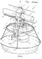
- This feeder consists of a suspended receptacle 2 of a type known per se, provided with support arms 3 and a member 4 for the distribution of food connected to a tubular conduit 5 oriented horizontally and intended for the transport of food from a silo (not shown).
- the support arms 3 are constituted by two round metal rods, each of which has in its central upper part a U-shape turned downwards, so as to constitute a sort of stirrup 3 'bearing on the duct 5, which stirrup is integral with 3 "extensions which diverge radially with respect to the vertical axis A of the dispensing member 4, adjacent to said stirrup 3 '.
- the ends 3"' of the arms 3 are folded back and engaged inside buttonholes 6 formed in the inverted edge 7 of receptacle 2.
- this member 4 is constituted on the one hand by a fixed distribution element 10 connected in the manner known per se to the tubular conduit 5, and on the other hand by an element 11 for adjusting the level of food, this element 11 being disposed around said fixed element 10 so as to be able to be displaced co-axially with respect thereto.
- the distribution element 10 comprises a substantially cylindrical hollow body 12 provided on the one hand with an upward head 13 with a square or rectangular section whose apex 14 is convex, on the other hand downwards d an annular part 15 of diameter greater than that of the body 12 and which is connected to the latter by radial spacers 16.
- the top 14 comprises a support 17 inside which is engaged the usual electrical conductor 18 intended to prevent poultry from perching on the conduit 5.
- the adjusting element 11 is shaped substantially in the manner a cylindrical sleeve, the top 19 of which has a frustoconical profile, while the base is provided with a bottom 20 with an external profile which is itself frustoconical; this bottom 20 is secured to a lower part 21 with a cylindrical profile, suitable for preventing poultry from engaging the spout in the zone between the outer wall of said bottom 20 and the conical boss 22 provided in the traditional manner in the central part receptacle 2.
- the leveling element 11 is of the kind capable of moving along the element 10 and it is supported and actuated in this movement by an operating cable constituted by a rope 23 folded back on itself, the ends 24 are fixed to the upper part of this element 11 and which is slidably engaged through two perforated ears 25 acting as references and attached to the head 13 diametrically opposite one another with respect to the axis A.
- This cord 23 is made integral with the using jaw 26, a main cable 27 oriented parallel to the conduit 5 below the latter; this cable 27 is actuated by means of a suitable central device 28 (FIG. 2) which is thus capable of ensuring the adjustment of the level of the food simultaneously in all the feeders 1.
- the main cable 27 freely crosses the head 13 of each feeder by means of a through opening 29 (fig. 1) oriented perpendicular to the axis A and shaped like a light in order to allow oscillations. possible feeder around the axis of the conduit 5 without subjecting said cable to a tensile force which would cause the untimely movement of the elements operating the adjustment of the level of food in the neighboring feeders.
- the external wall of the hollow cylindrical body 12 comprises two vertical guides 30 diametrically opposite one another with respect to the axis A and each of which is defined by two profiled ribs 31 between which slides a relief 32 integral with the external cylindrical surface of the adjusting element 11.
- each guide 30 Near its top each guide 30 has a lateral opening 33 which allows the relief of the relief 32 envisaged; this release (and similarly the engagement) is operated by rotating the adjusting element 11 around the axis A.
- two recesses 34 suitably positioned relative to the reliefs 32 in order to allow the passage of the ears 25 during assembly (or disengagement) of the elements 10 and 11.
- connection between the support arms 3 and the distribution member 4 is ensured by means of a series of profiled bosses 35 provided on the head 13 near the openings made therein to accommodate the ends of the conduit 5; it is between these bosses 35 that the upper part 3 ′ fits in the form of a stirrup of the support arms 3.
- Fig. 3 shows clearly the adjustment of the level of food in the feeders, these being likely to be elevated as the poultry grows independently of the above-mentioned setting.
Landscapes
- Life Sciences & Earth Sciences (AREA)
- Environmental Sciences (AREA)
- Birds (AREA)
- Animal Husbandry (AREA)
- Biodiversity & Conservation Biology (AREA)
- Feeding And Watering For Cattle Raising And Animal Husbandry (AREA)
- Housing For Livestock And Birds (AREA)
- Catching Or Destruction (AREA)
Abstract
Description
- La présente invention a trait aux mangeoires pour l'élevage de la volaille de grande taille, des dindons en particulier, et elle vise plus spécialement celles qui comprennent un réceptacle circulaire associé à des moyens pour le réglage du niveau des aliments et qui sont destinées à être utilisées en nombre le long des lignes de distribution d'aliments prévues dans les locaux d'aviculture.
- On sait que chacune de ces lignes de distribution est constituée en pratique par un conduit tubulaire orienté à l'horizontale au-dessus du sol et à l'intérieur duquel les aliments sont déplacés à l'aide de vis sans fin ou dispositifs similaires, depuis un silo central jusqu'aux mangeoires alignées au-dessous de la ligne considérée. Le réceptacle de chaque mangeoire est alimenté à travers un organe de distribution qui est relié au conduit sus-mentionné et qui est constitué essentiellement par un élément cylindrique creux dont la position, prévue réglable, par rapport au réceptacle détermine le niveau des aliments dans ce dernier, le réglage étant effectué en fonction de la taille (c'est-à-dire, en fait, de l'âge) des volailles auxquelles lesdits aliments sont destinés.
- A l'heure actuelle le réglage du niveau des aliments dans le réceptacle est assuré moyennant une intervention séparée au niveau de l'organe de distribution de chaque mangeoire, ce qui implique évidemment une part de mains d'oeuvre considérable. De plus le réceptacle des mangeoires connues à ce jour est rendu solidaire de l'organe de distribution au moyen de bras appropriés de soutien prévus rayonnants, l'organe précité étant lui-même relié au conduit horizontal de transport d'aliments.
- Cette disposition implique bien entendu un inconvénient quant à la robustesse de la mangeoire, notamment lorsque celle-ci est destinée à l'alimentation de volailles de grande taille telles que les dindons ; cet inconvénient est encore plus accentué du fait que l'organe de distribution est le plus souvent réalisé en matière plastique.
- C'est à ces défauts qu'entend essentiellement remédier la présente invention, et ce en permettant la réalisation d'une mangeoire plus particulièrement destinée aux volailles d'élevage de grande taille, qui présente une robustesse parfaite et qui rende en même temps possible le réglage du niveau des aliments moyennant une manoeuvre simple et rapide, susceptible d'être effectuée depuis un poste central du local d'aviculture.
- La mangeoire suivant l'invention, du type destiné à être disposé en nombre le long des lignes de distribution des aliments dans les locaux et comprenant un réceptacle suspendu par une série de bras-supports rayonnants et au-dessus duquel est prévu un organe distributeur d'aliments prévu creux qui est relié et qui communique avec un conduit horizontal tubulaire pour le transport des aliments provenant d'un silo, lequel organe distributeur comprend lui-même un élément fixe de répartition et un élément pour le réglage du niveau des aliments conformé à la manière d'un manchon substantiellement cylindrique, mobile à l'extérieur de l'élément de répartition sus-mentionné, est caractérisée en ce que les bras-supports sont directement reliés au conduit tubulaire, tandis qu'en vue d'en permettre le déplacement vertical entre une position inférieure proche du fond du réceptacle et une position supérieure, l'élément de réglage de niveau est soutenu et actionné par des câbles de manoeuvre reliés, à travers des organes de renvoi, à un câble principal disposé parallèlement audit conduit et établi à la longueur de celui-ci, ledit câble principal étant associé à un mécanisme central de commande.
- i D'autres dispositions remarquables de la mangeoire ressortiront de la description qui va suivre en référence au dessin annexé, lequel dessin, donné à titre d'exemple, permettra de mieux comprendre l'invention, les caractéristiques qu'elle présente et les avantages qu'elle est susceptible de procurer :
- Fig. 1 est une vue en perspective avec arrachements montrant l'agencement général de la mangeoire.
- Fig. 2 est une vue schématique de côté d'une ligne de distribution équipée d'une série de mangeoires suivant fig. 1.
- Fig. 3 illustre, à trois positions différentes, le réglage de l'une des mangeoires de fig. 2.
- Sur ce dessin la référence 1 désigne globalement une mangeoire suivant l'invention. Cette mangeoire est constituée par un réceptacle suspendu 2 de type en soi connu, pourvu de bras-supports 3 et d'un organe 4 pour la distribution des aliments relié à un conduit tubulaire 5 orienté horizontalement et destiné au transport des aliments provenant d'un silo (non représenté).
- Comme montré en fig. 1 les bras-supports 3 sont constitués par deux tiges rondes en métal, dont chacune présente dans sa partie supérieure centrale une forme en U tourné vers le bas, de façon à constituer une sorte d'étrier 3' prenant appui sur le conduit 5, lequel étrier est solidaire de prolongements 3" qui divergent radialement par rapport à l'axe vertical A de l'organe de distribution 4, adjacent audit étrier 3'. Les extrémités 3"' des bras 3 sont repliées et engagées à l'intérieur de boutonnières 6 ménagées dans le bord retourné 7 du réceptacle 2.
- On observera que par suite de leur réalisation sous forme de tiges métalliques rondes, les bras-supports 3 sont susceptibles de se déformer élastiquement et d'être dégagés des boutonnières 6 moyennant une simple pression exercée sur leur extrémité 3"' suivant une direction substantiellement centripète par rapport à l'axe A. On a figuré en 8 un renfort annulaire apte à rigidifier la partie supérieure des bras 3 auxquels il est fixé par des rivets tels que 9. La structure ainsi obtenue est en conséquence totalement indépendante de l'organe de distribution 4.
- Comme illustré en fig. 1 cet organe 4 est constitué d'une part par un élément fixe de répartition 10 relié à la façon en soi connue au conduit tubulaire 5, et d'autre part par un élément 11 pour le réglage du niveau des aliments, cet élément 11 étant disposé autour dudit élément fixe 10 de façon à pouvoir être déplacé co-axialement par rapport à celui-ci.
- De manière plus précise l'élément de répartition 10 comprend un corps creux 12 substantiellement cylindrique pourvu d'une part vers le haut d'une tête 13 à section carrée ou rectangulaire dont le sommet 14 est convexe, d'autre part vers le bas d'une partie annulaire 15 de diamètre supérieur à celui du corps 12 et qui est reliée à celui-ci par des entretoises radiales 16.
- Le sommet 14 comporte un support 17 à l'intérieur duquel est engagé le conducteur électrique usuel 18 destiné à interdire à la volaille de se percher sur le conduit 5. On notera par ailleurs que l'élément de réglage 11 est conformé substantiellement à la manière d'un manchon cylindrique dont le sommet 19 présente un profil tronconique, tandis que la base est dotée d'un fond 20 à profil extérieur lui-même tronconique ; ce fond 20 est solidaire d'une partie inférieure 21 à profil cylindrique, propre à empêcher la volaille d'engager le bec dans la zone comprise entre la paroi extérieure dudit fond 20 et le bossage conique 22 prévu à la manière traditionnelle dans la partie centrale du réceptacle 2.
- L'élément de réglage de niveau 11 est de la sorte susceptible de se déplacer le long de l'élément 10 et il est soutenu et actionné dans ce mouvement par un câble de manoeuvre constitué par une corde 23 repliée sur elle-même, dont les extrémités 24 sont fixées à la partie supérieure de cet élément 11 et qui est engagée à coulissement à travers deux oreilles perforées 25 faisant fonction de renvois et rapportées sur la tête 13 diamétralement à l'opposé l'une de l'autre par rapport à l'axe A. Cette corde 23 est rendue solidaire, à l'aide de mors 26, d'un câble principal 27 orienté parallèlement au conduit 5 au-dessous de celui-ci ; ce câble 27 est actionné au moyen d'un dispositif central approprié 28 (fig. 2) qui est ainsi susceptible d'assurer le réglage du niveau des aliments simultanément dans toutes les mangeoires 1.
- On observera que le câble principal 27 traverse librement la tête 13 de chaque mangeoire par le moyen d'une ouverture traversante 29 (fig. 1) orientée perpendiculairement à l'axe A et conformée à la manière d'une lumière afin de permettre les oscillations éventuelles de la mangeoire autour de l'axe du conduit 5 sans soumettre ledit câble à un effort de traction qui provoquerait le déplacement intempestif des éléments opérant le réglage du niveau des aliments dans les mangeoires voisines.
- Comme illustré en fig. 1 la paroi externe du corps cylindrique creux 12 comporte deux guides verticaux 30 diamétralement opposés l'un à l'autre par rapport à l'axe A et dont chacun est défini par deux nervures profilées 31 entre lesquelles vient coulisser un relief 32 solidaire de la surface cylindrique extérieure de l'élément de réglage 11. A proximité de son sommet chaque guide 30 présente une ouverture latérale 33 qui permet le dégagement du relief 32 envisagé ; ce dégagement (et de manière analogue l'engagement) est opéré en faisant tourner l'élément de réglage 11 autour de l'axe A. On notera à ce sujet que dans la partie supérieure de cet élément 11 sont prévues deux creusures 34 convenablement positionnées par rapport aux reliefs 32 afin de permettre le passage des oreilles 25 lors du montage (ou du dégagement) des éléments 10 et 11.
- La liaison entre les bras-supports 3 et l'organe de distribution 4 est assurée à l'aide d'une série de bossages profilés 35 prévus sur la tête 13 à proximité des ouvertures pratiquées dans celle-ci pour loger les extrémités du conduit 5 ; c'est entre ces bossages 35 que vient s'adapter la partie supérieure 3' en forme d'étrier des bras-supports 3.
- Fig. 3 fait bien apparaître le réglage du niveau des aliments dans les mangeoires, celles-ci étant susceptibles d'être élevées au fur et à mesure de la croissance de la volaille indépendamment du réglage sus-indiqué.
Claims (9)
Priority Applications (1)
| Application Number | Priority Date | Filing Date | Title |
|---|---|---|---|
| AT84200993T ATE58455T1 (de) | 1983-07-13 | 1984-07-09 | Futtertrog mit niveauregelung fuer die aufzucht von gefluegel. |
Applications Claiming Priority (2)
| Application Number | Priority Date | Filing Date | Title |
|---|---|---|---|
| IT8495083 | 1983-07-13 | ||
| IT84950/83A IT1175175B (it) | 1983-07-13 | 1983-07-13 | Mangiatoia con regolazione di livello del mangime per volatili d'allevamento, in particolare per tacchini |
Publications (3)
| Publication Number | Publication Date |
|---|---|
| EP0132004A2 true EP0132004A2 (fr) | 1985-01-23 |
| EP0132004A3 EP0132004A3 (en) | 1986-10-08 |
| EP0132004B1 EP0132004B1 (fr) | 1990-11-22 |
Family
ID=11326317
Family Applications (1)
| Application Number | Title | Priority Date | Filing Date |
|---|---|---|---|
| EP84200993A Expired - Lifetime EP0132004B1 (fr) | 1983-07-13 | 1984-07-09 | Mangeoire à niveau réglable pour l'élevage de la volaille |
Country Status (7)
| Country | Link |
|---|---|
| US (1) | US4552095A (fr) |
| EP (1) | EP0132004B1 (fr) |
| AT (1) | ATE58455T1 (fr) |
| AU (1) | AU560724B2 (fr) |
| DE (1) | DE3483631D1 (fr) |
| ES (1) | ES280499Y (fr) |
| IT (1) | IT1175175B (fr) |
Cited By (2)
| Publication number | Priority date | Publication date | Assignee | Title |
|---|---|---|---|---|
| GB2218611A (en) * | 1988-05-20 | 1989-11-22 | Net Tex Agricultural Limited | Apparatus for feeding lambs |
| EP0913085A1 (fr) * | 1997-11-03 | 1999-05-06 | Ctb, Inc. | Mangeoire réglable pour volailles |
Families Citing this family (43)
| Publication number | Priority date | Publication date | Assignee | Title |
|---|---|---|---|---|
| AU606507B2 (en) * | 1988-03-16 | 1991-02-07 | Morton, Beryl Joan | Poultry and like feeder |
| USD302750S (en) | 1988-06-09 | 1989-08-08 | Ctb, Inc. | Poultry feeder |
| NL8801692A (nl) * | 1988-07-04 | 1990-02-01 | Elite Nv | Voederpan voor varkens en biggen. |
| ES2010080A6 (es) * | 1989-01-13 | 1989-10-16 | Tigsa | Comedero para aves. |
| NL8902461A (nl) * | 1989-10-04 | 1991-05-01 | Roxell Nv | Instelbare voederinrichting voor pluimvee. |
| US5097797A (en) * | 1989-10-23 | 1992-03-24 | Intraco, Inc. | Poultry feeder |
| IT1239319B (it) * | 1990-04-11 | 1993-10-19 | Ska | Mangiatoia con regolazione di livello del mangime. |
| US5092274A (en) * | 1990-10-30 | 1992-03-03 | Ctb, Inc. | Poultry feeder |
| IT224331Z2 (it) * | 1991-03-04 | 1996-03-14 | Ska Spa | Mangiatoia per lo svezzamento di volatili d'allevamento in particolare tacchini |
| ES2078203T3 (es) * | 1992-12-15 | 1997-04-01 | Grain Systems Inc | Comedero para aves. |
| ES2080652B1 (es) * | 1993-06-14 | 1998-05-01 | Agropecuaria Felip S A | Dispositivo para distribucion de pienso granulado. |
| US5406907A (en) * | 1993-11-24 | 1995-04-18 | Big Dutchman Inc. | Controlled pan feeder system for poultry |
| US6050220A (en) * | 1997-05-23 | 2000-04-18 | Pax Steel Products, Inc. | Poultry feeder with adjustable feed level control |
| US5927232A (en) * | 1997-08-22 | 1999-07-27 | Gsi Group, Inc. | Poultry feeder |
| US6474261B1 (en) * | 2001-04-18 | 2002-11-05 | Val-Co Pax, Inc. | Poultry feeder with feed conveyor control system |
| DE10164122C1 (de) * | 2001-12-24 | 2003-05-15 | Big Dutchman Int Gmbh | Vorrichtung für die Fütterung von Geflügel, insbesondere Mastgeflügel, vorzugsweise Broiler |
| DE10164100C1 (de) * | 2001-12-24 | 2003-04-03 | Big Dutchman Int Gmbh | Vorrichtung für die Fütterung von Geflügel, insbesondere Mastgeflügel, vorzugsweise Broiler |
| AU2003237442A1 (en) * | 2002-06-26 | 2004-01-19 | Ctb, Inc. | Poultry feeder |
| USD498565S1 (en) | 2003-06-17 | 2004-11-16 | Ctb Ip, Inc. | Rim and spokes of a grill for a feeder |
| USD499218S1 (en) | 2003-06-17 | 2004-11-30 | Ctb Ip, Inc. | Rim of a grill for a feeder |
| USD530045S1 (en) | 2003-06-23 | 2006-10-10 | Ctb Ip, Inc. | Section of a rim for a feeder |
| USD491320S1 (en) | 2003-06-23 | 2004-06-08 | Ctb Ip, Inc. | Rim for a feed pan |
| USD491696S1 (en) | 2003-06-25 | 2004-06-15 | Ctb Ip Inc. | Feed pan |
| USD542981S1 (en) | 2005-07-29 | 2007-05-15 | Ctb Ip, Inc. | Poultry feeder |
| US7581512B2 (en) | 2005-10-11 | 2009-09-01 | Ctb, Inc. | Pan breeder feeder |
| US7584716B2 (en) | 2005-10-11 | 2009-09-08 | Ctb, Inc. | Pan breeder feeder |
| US7587990B2 (en) | 2005-10-11 | 2009-09-15 | Ctb, Inc. | Pan breeder feeder |
| USD583112S1 (en) | 2006-10-10 | 2008-12-16 | Ctb, Inc. | Grill of a feeder assembly |
| USD564712S1 (en) | 2006-10-10 | 2008-03-18 | Ctb Ip, Inc. | Pan of a feeder assembly |
| ES2372139B1 (es) * | 2009-06-25 | 2012-11-23 | Zucami, S.L. | Comedero de aves. |
| ITMI20100561A1 (it) * | 2010-04-01 | 2011-10-02 | Paolo Pirovano | Impianto di distribuzione controllata di materiale a comportamento sostanzialmente fluido per l'alimentazione animale |
| US9572326B2 (en) * | 2011-12-02 | 2017-02-21 | Valco Companies, Inc. | Poultry feeder with beak grooming device |
| US9382070B2 (en) | 2012-10-24 | 2016-07-05 | Big Dutchman International Gmbh | Conveyor and method to convey animal products in an agricultural business |
| USD701654S1 (en) * | 2013-06-18 | 2014-03-25 | Francisco Javier Septien Prieto | Bird feeder |
| DE202014007282U1 (de) | 2014-09-12 | 2015-12-16 | Big Dutchman International Gmbh | Dosiervorrichtung |
| CN105145391A (zh) * | 2015-10-12 | 2015-12-16 | 俞升洋 | 一种气压控制升降的饲料供应装置 |
| CN105165643A (zh) * | 2015-10-12 | 2015-12-23 | 钱国臣 | 一种能自动调节的饲料供应装置 |
| CN105165642A (zh) * | 2015-10-12 | 2015-12-23 | 范盛林 | 一种电机控制速度可调的饲料供应装置 |
| CN106035127B (zh) * | 2016-05-31 | 2019-06-07 | 广西金陵农牧集团有限公司 | 一种养鸡用自动喂食装置及其应用 |
| DE202016105370U1 (de) | 2016-09-27 | 2018-01-02 | Big Dutchman International Gmbh | Fütterungsvorrichtung für Geflügeltiere |
| IT201800006493A1 (it) * | 2018-06-20 | 2019-12-20 | Mangiatoia per l'allevamento di animali con regolazione migliorata del livello di mangime | |
| USD890446S1 (en) * | 2018-10-25 | 2020-07-14 | Gerald L. Watercutter | Poultry feeder pan with a pivotable drop down center cone |
| USD952265S1 (en) * | 2019-07-11 | 2022-05-17 | Francisco Javier Septien Prieto | Industrial food dispenser model for animals |
Family Cites Families (5)
| Publication number | Priority date | Publication date | Assignee | Title |
|---|---|---|---|---|
| DE1181482B (de) * | 1963-11-08 | 1964-11-12 | P Lecieux & Cie S A R L Ets | Vorrichtung zur automatischen Beschickung von Futtertellern |
| FR1414692A (fr) * | 1964-11-27 | 1965-10-15 | Appareil automatique pour l'alimentation d'animaux, tels que volailles, lapins ou autres | |
| US3388690A (en) * | 1965-10-22 | 1968-06-18 | Chore Time Equipment | Poultry feeder system and pan assembly therefor |
| US3490419A (en) * | 1967-06-19 | 1970-01-20 | Us Industries Inc | Poultry and animal feeder apparatus |
| US3971340A (en) * | 1974-08-19 | 1976-07-27 | U.S. Industries, Inc. | Limit and control feeder for animals |
-
1983
- 1983-07-13 IT IT84950/83A patent/IT1175175B/it active
-
1984
- 1984-06-27 US US06/625,030 patent/US4552095A/en not_active Expired - Fee Related
- 1984-06-28 AU AU29988/84A patent/AU560724B2/en not_active Ceased
- 1984-07-09 EP EP84200993A patent/EP0132004B1/fr not_active Expired - Lifetime
- 1984-07-09 DE DE8484200993T patent/DE3483631D1/de not_active Expired - Fee Related
- 1984-07-09 AT AT84200993T patent/ATE58455T1/de not_active IP Right Cessation
- 1984-07-12 ES ES1984280499U patent/ES280499Y/es not_active Expired
Cited By (2)
| Publication number | Priority date | Publication date | Assignee | Title |
|---|---|---|---|---|
| GB2218611A (en) * | 1988-05-20 | 1989-11-22 | Net Tex Agricultural Limited | Apparatus for feeding lambs |
| EP0913085A1 (fr) * | 1997-11-03 | 1999-05-06 | Ctb, Inc. | Mangeoire réglable pour volailles |
Also Published As
| Publication number | Publication date |
|---|---|
| IT8384950A0 (it) | 1983-07-13 |
| ES280499U (es) | 1985-01-16 |
| US4552095A (en) | 1985-11-12 |
| DE3483631D1 (de) | 1991-01-03 |
| AU2998884A (en) | 1985-01-17 |
| IT1175175B (it) | 1987-07-01 |
| EP0132004B1 (fr) | 1990-11-22 |
| EP0132004A3 (en) | 1986-10-08 |
| ATE58455T1 (de) | 1990-12-15 |
| ES280499Y (es) | 1985-07-16 |
| AU560724B2 (en) | 1987-04-16 |
Similar Documents
| Publication | Publication Date | Title |
|---|---|---|
| EP0132004B1 (fr) | Mangeoire à niveau réglable pour l'élevage de la volaille | |
| EP0988787B1 (fr) | Dispositif d'alimentation d'animaux tels que des volailles | |
| FR2717724A1 (fr) | Installation de soudage automatique. | |
| FR2520979A1 (fr) | Installation pour la decoupe de carcasses d'animaux et dispositif d'accrochage de telles carcasses | |
| FR3026275A1 (fr) | Nourrisseur a regulation amelioree de la distribution de nourriture | |
| EP0951825A1 (fr) | Mangeoire pour volailles, utilisée notamment dans une installation d'alimentation de vollailes | |
| EP2173222A2 (fr) | Dispositif pour la présentation et la conservation de bouquets de fleurs | |
| FR2553467A1 (fr) | Persienne enroulable | |
| FR2678480A1 (fr) | Mangeoire avicole et installation de distribution d'aliments qui en est equipee. | |
| EP0035424B1 (fr) | Echafaudage volant pour bâtiment | |
| FR2651960A1 (fr) | Dispositif pour le taillage de haies. | |
| EP0895714B1 (fr) | Cornadis de sécurité | |
| WO2008000311A1 (fr) | Dispositif de tuteurage pour plantes grimpantes | |
| FR2508765A1 (fr) | Support pour canne a peche | |
| EP0097406B1 (fr) | Dispositif pour attacher un animal | |
| FR2668970A1 (fr) | Dispositif distributeur de ressorts. | |
| FR2722648A1 (fr) | Olailles dispositif d'alimentation d'animaux tels que des v | |
| FR2794143A3 (fr) | Dispositif de delivrance de fil pour une machine a tricoter jacquard | |
| FR2685854A1 (fr) | Mangeoire avicole et installation de distribution d'aliments qui en est equipee. | |
| FR3035570A3 (fr) | Modele de pare-soleil | |
| FR2760605A1 (fr) | Dispositif de protection de type parasol ou parapluie a mat excentre | |
| FR2736081A1 (fr) | Parasol a pied deporte | |
| FR2767023A1 (fr) | Dispositif pour l'alimentation du betail | |
| FR2732575A3 (fr) | Dispositif pour la mise en place d'un sapin a tronc coupe en position verticale, notamment d'un sapin de noel | |
| FR2663194A1 (fr) | Piege pour animaux. |
Legal Events
| Date | Code | Title | Description |
|---|---|---|---|
| PUAI | Public reference made under article 153(3) epc to a published international application that has entered the european phase |
Free format text: ORIGINAL CODE: 0009012 |
|
| AK | Designated contracting states |
Designated state(s): AT BE CH DE FR GB IT LI LU NL SE |
|
| PUAL | Search report despatched |
Free format text: ORIGINAL CODE: 0009013 |
|
| AK | Designated contracting states |
Kind code of ref document: A3 Designated state(s): AT BE CH DE FR GB IT LI LU NL SE |
|
| 17P | Request for examination filed |
Effective date: 19870408 |
|
| 17Q | First examination report despatched |
Effective date: 19880704 |
|
| GRAA | (expected) grant |
Free format text: ORIGINAL CODE: 0009210 |
|
| AK | Designated contracting states |
Kind code of ref document: B1 Designated state(s): AT BE CH DE FR GB IT LI LU NL SE |
|
| PG25 | Lapsed in a contracting state [announced via postgrant information from national office to epo] |
Ref country code: SE Effective date: 19901122 Ref country code: AT Effective date: 19901122 |
|
| REF | Corresponds to: |
Ref document number: 58455 Country of ref document: AT Date of ref document: 19901215 Kind code of ref document: T |
|
| REF | Corresponds to: |
Ref document number: 3483631 Country of ref document: DE Date of ref document: 19910103 |
|
| ITF | It: translation for a ep patent filed | ||
| GBT | Gb: translation of ep patent filed (gb section 77(6)(a)/1977) | ||
| ITTA | It: last paid annual fee | ||
| PG25 | Lapsed in a contracting state [announced via postgrant information from national office to epo] |
Ref country code: LU Free format text: LAPSE BECAUSE OF NON-PAYMENT OF DUE FEES Effective date: 19910731 |
|
| PLBE | No opposition filed within time limit |
Free format text: ORIGINAL CODE: 0009261 |
|
| STAA | Information on the status of an ep patent application or granted ep patent |
Free format text: STATUS: NO OPPOSITION FILED WITHIN TIME LIMIT |
|
| 26N | No opposition filed | ||
| PGFP | Annual fee paid to national office [announced via postgrant information from national office to epo] |
Ref country code: GB Payment date: 19940707 Year of fee payment: 11 |
|
| PGFP | Annual fee paid to national office [announced via postgrant information from national office to epo] |
Ref country code: CH Payment date: 19940719 Year of fee payment: 11 |
|
| PGFP | Annual fee paid to national office [announced via postgrant information from national office to epo] |
Ref country code: FR Payment date: 19940722 Year of fee payment: 11 |
|
| PGFP | Annual fee paid to national office [announced via postgrant information from national office to epo] |
Ref country code: BE Payment date: 19940729 Year of fee payment: 11 |
|
| PGFP | Annual fee paid to national office [announced via postgrant information from national office to epo] |
Ref country code: NL Payment date: 19940731 Year of fee payment: 11 |
|
| PGFP | Annual fee paid to national office [announced via postgrant information from national office to epo] |
Ref country code: DE Payment date: 19940928 Year of fee payment: 11 |
|
| PG25 | Lapsed in a contracting state [announced via postgrant information from national office to epo] |
Ref country code: GB Effective date: 19950709 |
|
| PG25 | Lapsed in a contracting state [announced via postgrant information from national office to epo] |
Ref country code: LI Effective date: 19950731 Ref country code: CH Effective date: 19950731 Ref country code: BE Effective date: 19950731 |
|
| BERE | Be: lapsed |
Owner name: SKA S.P.A. Effective date: 19950731 |
|
| PG25 | Lapsed in a contracting state [announced via postgrant information from national office to epo] |
Ref country code: NL Effective date: 19960201 |
|
| GBPC | Gb: european patent ceased through non-payment of renewal fee |
Effective date: 19950709 |
|
| REG | Reference to a national code |
Ref country code: CH Ref legal event code: PL |
|
| NLV4 | Nl: lapsed or anulled due to non-payment of the annual fee |
Effective date: 19960201 |
|
| PG25 | Lapsed in a contracting state [announced via postgrant information from national office to epo] |
Ref country code: DE Effective date: 19960402 |
|
| PG25 | Lapsed in a contracting state [announced via postgrant information from national office to epo] |
Ref country code: FR Effective date: 19960430 |
|
| REG | Reference to a national code |
Ref country code: FR Ref legal event code: ST |
|
| REG | Reference to a national code |
Ref country code: FR Ref legal event code: ST |
|
| REG | Reference to a national code |
Ref country code: FR Ref legal event code: ST |