EP0130098B1 - Auslauf zum Ausströmen von Flüssigkeiten - Google Patents
Auslauf zum Ausströmen von Flüssigkeiten Download PDFInfo
- Publication number
- EP0130098B1 EP0130098B1 EP84401083A EP84401083A EP0130098B1 EP 0130098 B1 EP0130098 B1 EP 0130098B1 EP 84401083 A EP84401083 A EP 84401083A EP 84401083 A EP84401083 A EP 84401083A EP 0130098 B1 EP0130098 B1 EP 0130098B1
- Authority
- EP
- European Patent Office
- Prior art keywords
- flat chamber
- flow spout
- plate
- spout according
- flow
- Prior art date
- Legal status (The legal status is an assumption and is not a legal conclusion. Google has not performed a legal analysis and makes no representation as to the accuracy of the status listed.)
- Expired
Links
- 239000007788 liquid Substances 0.000 title claims description 6
- 239000000463 material Substances 0.000 claims description 4
- 239000012530 fluid Substances 0.000 claims description 3
- 239000011521 glass Substances 0.000 claims description 3
- 239000002184 metal Substances 0.000 claims description 3
- XLYOFNOQVPJJNP-UHFFFAOYSA-N water Substances O XLYOFNOQVPJJNP-UHFFFAOYSA-N 0.000 description 6
- 239000000945 filler Substances 0.000 description 1
- 230000005484 gravity Effects 0.000 description 1
- 238000004519 manufacturing process Methods 0.000 description 1
Images

Classifications
-
- E—FIXED CONSTRUCTIONS
- E03—WATER SUPPLY; SEWERAGE
- E03C—DOMESTIC PLUMBING INSTALLATIONS FOR FRESH WATER OR WASTE WATER; SINKS
- E03C1/00—Domestic plumbing installations for fresh water or waste water; Sinks
- E03C1/02—Plumbing installations for fresh water
- E03C1/04—Water-basin installations specially adapted to wash-basins or baths
- E03C1/0404—Constructional or functional features of the spout
-
- E—FIXED CONSTRUCTIONS
- E03—WATER SUPPLY; SEWERAGE
- E03C—DOMESTIC PLUMBING INSTALLATIONS FOR FRESH WATER OR WASTE WATER; SINKS
- E03C1/00—Domestic plumbing installations for fresh water or waste water; Sinks
- E03C1/02—Plumbing installations for fresh water
- E03C1/04—Water-basin installations specially adapted to wash-basins or baths
- E03C2001/0414—Water-basin installations specially adapted to wash-basins or baths allowing different orientations of the spout or the outlet nozzle
Definitions
- the present invention relates to a flow spout connected to at least one liquid inlet. It is particularly, although not exclusively, suitable for being used for the production of a bath filler spout.
- the jet emitted by the outlet spout according to the invention has the form of a curtain, which makes the filling of a bathtub less noisy. Furthermore, the flow spout according to the invention does not require a jet breaker, so that it is less sensitive to scaling than the known spouts.
- the slot is delimited between two parallel plates, made integral with one another in a sealed manner over their entire periphery, except at the location of the slot and these plates are arranged substantially horizontally, the upper plate serving as a tablet-like support.
- the edge of the plates adjacent to the slot is advantageously curved downward, in order to direct the curtain towards a bathtub to be filled.
- the subject of the present invention is an even quieter alternative embodiment of the above-mentioned flow spout.
- the outlet spout comprising a large flat chamber with a sharp blade, into which at least one liquid inlet opens, and which is in communication with the outside by a long and narrow slot, is remarkable in that it comprises a curved flow surface adjacent to the long and narrow slot, the concavity of the curve being directed upwards, said surface being constituted at least in part by generatrices parallel to each other and arranged so that its generatrices are at least approximately horizontal and its rear edge is at a level higher than its front edge, and in that said wide flat chamber is arranged so that its long and narrow slot is arranged on the side of said edge rear, adjacent and above said concave curved surface and at least substantially parallel to said generators.
- the front part of the concave surface progressively connects horizontally.
- the curtain of water exiting from said slot flows over said concave curved surface before falling into the bathtub or sink.
- this curtain of water loses part of its energy and has a concave, then convex shape.
- the curtain of water In its convex part, the curtain of water almost flows under the effect of gravity alone, which makes the spout particularly silent. In addition, it has a very original aesthetic effect.
- At least part of said wide flat chamber follows the upper part of said concave surface.
- said concave curved surface is constituted by a pallet.
- at least a part of said large flat chamber can match the convex part of said pallet.
- At least a part of said flat chamber conforms to the upper part of the concavity of said pallet, at least a part of said flat chamber conforms to the convex part of said pallet, and said parts of the flat chamber are joined by a 180 ° elbow enclosing the rear upper edge of said pallet.
- Said wide flat chamber may be integral with a housing surrounding the fluid inlet (s) and serving as a base for said concave curved surface.
- the pallet can be of any desired material, in particular it can be made of a metal or a transparent or translucent material, such as glass.
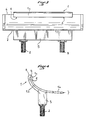
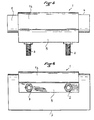
- the water flow spout according to the invention shown in these figures comprises a large flat chamber 1, in the form of a blade, into which liquid inlets 2 and 3 open and which is in communication with the outside by a long and narrow slit 4.
- This flow spout further comprises a curved pallet 5, the concave face of which faces upwards and which is constituted at least in part by a surface formed by generatrices parallel to each other.
- These generators are at least approximately horizontal and the rear edge 6 of the pallet 5 is at a level higher than the front edge 7 thereof.
- Chamber 1 slot 4 is arranged so as to be on the side of the rear edge 6, close to the concave face of the pallet 5 and substantially horizontal.
- the front part 5a of the pallet 5 is progressively connected with the horizontal.
- the flat chamber 1 comprises a part 1a which marries the concave part of the pallet 5 and a part 1b which partially marries the convex rear part of said pallet, the parts 1a and 1b of the chamber 1 being joined by an elbow 8 at 180 ° enclosing the rear upper edge 6 of the pallet 5.
- Chamber 1 is integral with a housing 9 surrounding the fluid inlets and serving as a base for the pallet 5.
- This pallet 5 can be of any desired material and in particular of metal or glass.
Landscapes
- Health & Medical Sciences (AREA)
- Life Sciences & Earth Sciences (AREA)
- Engineering & Computer Science (AREA)
- Hydrology & Water Resources (AREA)
- Public Health (AREA)
- Water Supply & Treatment (AREA)
- Nozzles (AREA)
- Closures For Containers (AREA)
- Indicating Or Recording The Presence, Absence, Or Direction Of Movement (AREA)
- Toys (AREA)
Claims (9)
Applications Claiming Priority (2)
| Application Number | Priority Date | Filing Date | Title |
|---|---|---|---|
| FR8310480A FR2547846B1 (fr) | 1983-06-24 | 1983-06-24 | Bec d'ecoulement pour liquide |
| FR8310480 | 1983-06-24 |
Publications (3)
| Publication Number | Publication Date |
|---|---|
| EP0130098A2 EP0130098A2 (de) | 1985-01-02 |
| EP0130098A3 EP0130098A3 (en) | 1985-09-11 |
| EP0130098B1 true EP0130098B1 (de) | 1987-09-09 |
Family
ID=9290145
Family Applications (1)
| Application Number | Title | Priority Date | Filing Date |
|---|---|---|---|
| EP84401083A Expired EP0130098B1 (de) | 1983-06-24 | 1984-05-25 | Auslauf zum Ausströmen von Flüssigkeiten |
Country Status (5)
| Country | Link |
|---|---|
| US (1) | US4513458A (de) |
| EP (1) | EP0130098B1 (de) |
| DE (1) | DE3466027D1 (de) |
| ES (1) | ES280017Y (de) |
| FR (1) | FR2547846B1 (de) |
Cited By (1)
| Publication number | Priority date | Publication date | Assignee | Title |
|---|---|---|---|---|
| DE4133639C1 (en) * | 1991-10-11 | 1993-04-29 | Markus Jehs | Design for water supply tap - in which water is fed over curved surface to dissipate energy to provide even supply. |
Families Citing this family (43)
| Publication number | Priority date | Publication date | Assignee | Title |
|---|---|---|---|---|
| USD291115S (en) | 1984-06-29 | 1987-07-28 | Jean-Claude Delepine | Spout |
| USD288117S (en) | 1984-07-19 | 1987-02-03 | Paul Associates, Inc. | Bathtub spout |
| USD291237S (en) | 1985-05-03 | 1987-08-04 | Jean-Claude Delepine | Faucet handle |
| USD304853S (en) | 1985-05-22 | 1989-11-28 | Sunset Collection S.P.R.L. | Faucet spout |
| USD290643S (en) | 1985-10-15 | 1987-06-30 | Paul Associates Inc. | Tub spout |
| USD290644S (en) | 1985-12-03 | 1987-06-30 | Paul Associates Inc. | Tub spout |
| USD299951S (en) | 1985-12-04 | 1989-02-21 | Sunset Collection Sprl. | Spout |
| USD290645S (en) | 1985-12-06 | 1987-06-30 | Paul Associates, Inc. | Tub spout |
| USD301517S (en) | 1987-01-12 | 1989-06-06 | Donald Anawalt | Spout |
| US4823409A (en) * | 1987-01-13 | 1989-04-25 | Kohler Co. | Sheet flow spout |
| USD312866S (en) | 1987-01-13 | 1990-12-11 | Kohler Co. | Spout |
| US4912782A (en) * | 1987-05-26 | 1990-04-03 | Kallista, Inc. | Fluid spout providing lamelliform outflow |
| GB2206951B (en) * | 1987-07-03 | 1991-05-01 | Bonsack Baths | Water outlets |
| USD320259S (en) | 1987-11-02 | 1991-09-24 | Jean-Claude Delepine | Faucet |
| US4852190A (en) * | 1988-03-18 | 1989-08-01 | Jason International, Inc. | Double cascade spout |
| USD315594S (en) | 1988-04-05 | 1991-03-19 | Harden Industries, Inc. | Spout |
| USD315016S (en) | 1988-04-05 | 1991-02-26 | Harden Industries, Inc. | Spout |
| USD321038S (en) | 1988-04-18 | 1991-10-22 | Jean-Claude Delepine | Faucet |
| USD326504S (en) | 1988-09-19 | 1992-05-26 | Kallista, Inc. | Spout |
| USD321039S (en) | 1988-12-12 | 1991-10-22 | Kallista, Inc. | Spout |
| USD322472S (en) | 1989-01-19 | 1991-12-17 | Kohler Co. | Spout |
| DE3908140C2 (de) * | 1989-03-13 | 2001-05-23 | Hansgrohe Ag | Sanitärarmatur |
| USD321553S (en) | 1989-04-10 | 1991-11-12 | Jean-Claude Delephine | Faucet |
| USD321245S (en) | 1989-08-14 | 1991-10-29 | Jean-Claude Delepine | Bath tub |
| USD334798S (en) | 1990-10-16 | 1993-04-13 | American Standard Inc. | Filler spout |
| USD337371S (en) | 1990-10-16 | 1993-07-13 | American Standard Inc. | Filler spout |
| USD335919S (en) | 1991-01-11 | 1993-05-25 | Kohler Co. | Spout |
| US5127111A (en) * | 1991-01-11 | 1992-07-07 | Kohler Co. | Sheet flow spout assembly |
| US5115974A (en) * | 1991-08-21 | 1992-05-26 | Hayward Industries, Inc. | Apparatus for providing a waterfall or a fountain |
| US5253811A (en) * | 1991-11-08 | 1993-10-19 | Kohler Co. | Sheet flow spout |
| USD341648S (en) | 1991-11-08 | 1993-11-23 | Kohler Co. | Spout |
| USD339854S (en) | 1991-11-08 | 1993-09-28 | Jacob Delafon | Spout |
| US5309581A (en) * | 1992-11-16 | 1994-05-10 | Lockwood Arthur D | Water steam apparatus |
| USD343444S (en) | 1993-05-20 | 1994-01-18 | Jacob Delafon | Faucet |
| ES2109007T3 (es) * | 1993-07-14 | 1998-01-01 | Kohler Co | Dispositivo para cuarto de baño con recirculacion de agua. |
| US6134722A (en) * | 1994-07-13 | 2000-10-24 | Kohler Co. | Recirculating bath fixture |
| DE19702037A1 (de) * | 1997-01-22 | 1998-07-23 | Grohe Kg Hans | Wannenauslauf |
| DE10219943B4 (de) * | 2002-05-03 | 2005-01-05 | Hansa Metallwerke Ag | Duschkopf |
| DE10261267B3 (de) * | 2002-12-27 | 2004-05-27 | Hansa Metallwerke Ag | Sanitäre Auslaufarmatur |
| US20060201561A1 (en) * | 2005-03-11 | 2006-09-14 | Clift Richard D | Spout for providing tranquil fluid flow |
| US20090218411A1 (en) * | 2007-11-08 | 2009-09-03 | Hansen Gorman P Erik | Water sheet showerhead |
| USD617422S1 (en) * | 2008-10-16 | 2010-06-08 | San-Ei Faucet Mfg. Co., Ltd. | Mixing faucet |
| USD975248S1 (en) * | 2022-09-23 | 2023-01-10 | Yunshi Deng | Faucet spout |
Family Cites Families (16)
| Publication number | Priority date | Publication date | Assignee | Title |
|---|---|---|---|---|
| GB576928A (de) * | ||||
| US1406030A (en) * | 1922-02-07 | John f | ||
| US1417583A (en) * | 1922-05-30 | Lavatoby fixture | ||
| US1383886A (en) * | 1919-09-25 | 1921-07-05 | Sr Jean F Webb | Water-silencer |
| US1408375A (en) * | 1921-01-15 | 1922-02-28 | Manelis Abraham | Hot and cold water mixer |
| US1512193A (en) * | 1922-07-07 | 1924-10-21 | Sigurd O Berven | Bathtur |
| GB201451A (en) * | 1922-10-03 | 1923-08-02 | Edward Richard Palmer | Improvements in or relating to baths fitted with spraying devices |
| CH161778A (de) * | 1931-08-22 | 1933-05-31 | Nussbaum & Co Aktiengesellscha | Wanne mit Füllbatterie. |
| US2679652A (en) * | 1951-05-10 | 1954-06-01 | John F Eyring | Bathtub |
| US2993213A (en) * | 1959-02-26 | 1961-07-25 | William H Carroll | Bath tub |
| BE679266A (de) * | 1966-04-08 | 1966-09-16 | ||
| FR2134957A5 (de) * | 1971-04-21 | 1972-12-08 | Abraco Sa | |
| DE2552786A1 (de) * | 1974-11-26 | 1976-07-01 | Leopold Zanoli | Vorrichtung zum einlassen von wasser in eine wanne |
| US4231123A (en) * | 1978-12-28 | 1980-11-04 | Cheng Yao Hui | Enamelled basin structure |
| FR2469212A1 (fr) * | 1979-11-16 | 1981-05-22 | Delepine Jean C | Bec d'ecoulement pour liquide |
| FR2478702A1 (fr) * | 1980-03-24 | 1981-09-25 | Munne Georges | Dispositif d'alimentation d'un appareil sanitaire tel qu'une baignoire |
-
1983
- 1983-06-24 FR FR8310480A patent/FR2547846B1/fr not_active Expired
-
1984
- 1984-05-23 US US06/613,256 patent/US4513458A/en not_active Expired - Lifetime
- 1984-05-25 EP EP84401083A patent/EP0130098B1/de not_active Expired
- 1984-05-25 DE DE8484401083T patent/DE3466027D1/de not_active Expired
- 1984-06-05 ES ES1984280017U patent/ES280017Y/es not_active Expired
Cited By (1)
| Publication number | Priority date | Publication date | Assignee | Title |
|---|---|---|---|---|
| DE4133639C1 (en) * | 1991-10-11 | 1993-04-29 | Markus Jehs | Design for water supply tap - in which water is fed over curved surface to dissipate energy to provide even supply. |
Also Published As
| Publication number | Publication date |
|---|---|
| EP0130098A3 (en) | 1985-09-11 |
| ES280017Y (es) | 1985-06-16 |
| DE3466027D1 (en) | 1987-10-15 |
| FR2547846A1 (fr) | 1984-12-28 |
| ES280017U (es) | 1984-12-16 |
| US4513458A (en) | 1985-04-30 |
| FR2547846B1 (fr) | 1986-06-20 |
| EP0130098A2 (de) | 1985-01-02 |
Similar Documents
| Publication | Publication Date | Title |
|---|---|---|
| EP0130098A2 (de) | Auslauf zum Ausströmen von Flüssigkeiten | |
| FR2469959A1 (fr) | Dispositif pour l'emission goutte a goutte de liquide | |
| FR2687058A1 (fr) | Accessoire pour cappuccino. | |
| EP3463002A1 (de) | Dämpferzubehör zum dampferhitzen und/oder -dämpfen von lebensmitteln in einem behälter | |
| EP0324115A1 (de) | Mixstab für Haushaltszwecke | |
| EP2960365B1 (de) | Elektrohaushaltsgerät zum bügeln, das einen behälter zur dampfdruckerzeugung umfasst, der mit einer druckauslassöffnung versehen ist | |
| FR2946857A3 (fr) | Composant integre de protection pour un lave-vaisselle | |
| EP1298390A1 (de) | Gasbrenner für Kochmulden | |
| FR3054572B1 (fr) | Module pour la realisation d'une barriere de protection contre les ecoulements de surface et barriere comportant au moins un tel module | |
| EP0319417A1 (de) | Strahllenker für sanitäre Installationen | |
| FR2905584A1 (fr) | Mixeur menager de type plongeant comportant un outil de travail presentant la forme d'une vis d'archimede. | |
| FR2573116A1 (fr) | Cloison de piscine a panneaux modulaires. | |
| FR2683570A1 (fr) | Sortie de toiture pour ventilation, en particulier pour ventilation mecanique controlee. | |
| FR2629115A1 (fr) | Appareil sanitaire a bec d'ecoulement integre | |
| FR2695668A1 (fr) | Dispositif de trop-plein, notamment pour réservoir de chasse d'eau. | |
| FR2498482A1 (fr) | Dispositif de placage | |
| CH654195A5 (fr) | Dispositif de lavage pour cuilleres a glace. | |
| WO2002009477A1 (fr) | Applicateur de micro-ondes focalisant | |
| FR2568346A1 (fr) | Ventouse pour reseau d'eau sous pression a poussee verticale importante | |
| FR2629372A1 (fr) | Dispositif pour le lavage d'elements de surface, tels que feux de signalisation | |
| FR2528561A1 (fr) | Radiateur, en particulier, pour moteurs thermiques | |
| EP0036361B1 (de) | Einbau-Spülbecken | |
| EP0006196A1 (de) | Warmwasserbereiter, insbesondere für Haushaltskaffeemaschinen | |
| EP0637717B1 (de) | Beleuchtungsvorrichtung mit eingebautem Lichtablenker | |
| FR2492248A1 (fr) | Joint d'etancheite pour porte de lave-vaisselle |
Legal Events
| Date | Code | Title | Description |
|---|---|---|---|
| PUAI | Public reference made under article 153(3) epc to a published international application that has entered the european phase |
Free format text: ORIGINAL CODE: 0009012 |
|
| AK | Designated contracting states |
Designated state(s): BE CH DE GB LI LU NL |
|
| PUAL | Search report despatched |
Free format text: ORIGINAL CODE: 0009013 |
|
| AK | Designated contracting states |
Designated state(s): BE CH DE GB LI LU NL |
|
| 17P | Request for examination filed |
Effective date: 19851108 |
|
| 17Q | First examination report despatched |
Effective date: 19861124 |
|
| GRAA | (expected) grant |
Free format text: ORIGINAL CODE: 0009210 |
|
| AK | Designated contracting states |
Kind code of ref document: B1 Designated state(s): BE CH DE GB LI LU NL |
|
| PG25 | Lapsed in a contracting state [announced via postgrant information from national office to epo] |
Ref country code: NL Effective date: 19870909 |
|
| REF | Corresponds to: |
Ref document number: 3466027 Country of ref document: DE Date of ref document: 19871015 |
|
| GBT | Gb: translation of ep patent filed (gb section 77(6)(a)/1977) | ||
| NLV1 | Nl: lapsed or annulled due to failure to fulfill the requirements of art. 29p and 29m of the patents act | ||
| PLBE | No opposition filed within time limit |
Free format text: ORIGINAL CODE: 0009261 |
|
| STAA | Information on the status of an ep patent application or granted ep patent |
Free format text: STATUS: NO OPPOSITION FILED WITHIN TIME LIMIT |
|
| 26N | No opposition filed | ||
| PGFP | Annual fee paid to national office [announced via postgrant information from national office to epo] |
Ref country code: LU Payment date: 19910627 Year of fee payment: 8 |
|
| EPTA | Lu: last paid annual fee | ||
| PGFP | Annual fee paid to national office [announced via postgrant information from national office to epo] |
Ref country code: CH Payment date: 19920430 Year of fee payment: 9 |
|
| PGFP | Annual fee paid to national office [announced via postgrant information from national office to epo] |
Ref country code: GB Payment date: 19920508 Year of fee payment: 9 |
|
| PG25 | Lapsed in a contracting state [announced via postgrant information from national office to epo] |
Ref country code: LU Free format text: LAPSE BECAUSE OF NON-PAYMENT OF DUE FEES Effective date: 19920525 |
|
| PGFP | Annual fee paid to national office [announced via postgrant information from national office to epo] |
Ref country code: BE Payment date: 19920703 Year of fee payment: 9 |
|
| PG25 | Lapsed in a contracting state [announced via postgrant information from national office to epo] |
Ref country code: GB Effective date: 19930525 |
|
| PG25 | Lapsed in a contracting state [announced via postgrant information from national office to epo] |
Ref country code: LI Effective date: 19930531 Ref country code: CH Effective date: 19930531 Ref country code: BE Effective date: 19930531 |
|
| BERE | Be: lapsed |
Owner name: DELEPINE JEAN CLAUDE Effective date: 19930531 |
|
| GBPC | Gb: european patent ceased through non-payment of renewal fee |
Effective date: 19930525 |
|
| REG | Reference to a national code |
Ref country code: CH Ref legal event code: PL |
|
| PGFP | Annual fee paid to national office [announced via postgrant information from national office to epo] |
Ref country code: DE Payment date: 19970422 Year of fee payment: 14 |
|
| PG25 | Lapsed in a contracting state [announced via postgrant information from national office to epo] |
Ref country code: DE Free format text: LAPSE BECAUSE OF NON-PAYMENT OF DUE FEES Effective date: 19990302 |