EP0129957A2 - Apparat und Verfahren zur Sicherung von Kabelträgerrollen - Google Patents
Apparat und Verfahren zur Sicherung von Kabelträgerrollen Download PDFInfo
- Publication number
- EP0129957A2 EP0129957A2 EP84302163A EP84302163A EP0129957A2 EP 0129957 A2 EP0129957 A2 EP 0129957A2 EP 84302163 A EP84302163 A EP 84302163A EP 84302163 A EP84302163 A EP 84302163A EP 0129957 A2 EP0129957 A2 EP 0129957A2
- Authority
- EP
- European Patent Office
- Prior art keywords
- cap
- axle
- fastener
- bolt
- locking
- Prior art date
- Legal status (The legal status is an assumption and is not a legal conclusion. Google has not performed a legal analysis and makes no representation as to the accuracy of the status listed.)
- Withdrawn
Links
Images
Classifications
-
- B—PERFORMING OPERATIONS; TRANSPORTING
- B61—RAILWAYS
- B61B—RAILWAY SYSTEMS; EQUIPMENT THEREFOR NOT OTHERWISE PROVIDED FOR
- B61B12/00—Component parts, details or accessories not provided for in groups B61B7/00 - B61B11/00
- B61B12/06—Safety devices or measures against cable fracture
-
- B—PERFORMING OPERATIONS; TRANSPORTING
- B61—RAILWAYS
- B61B—RAILWAY SYSTEMS; EQUIPMENT THEREFOR NOT OTHERWISE PROVIDED FOR
- B61B12/00—Component parts, details or accessories not provided for in groups B61B7/00 - B61B11/00
- B61B12/02—Suspension of the load; Guiding means, e.g. wheels; Attaching traction cables
Definitions
- the present invention relates, in general, to apparatus for retaining a member on an axle or the like, and more particularly, relates to apparatus for retaining a wheel or sheave assembly on an axle, including means to prevent removal of the sheave as a result of rotation and/or vibration.
- Aerial tramways such as chairlifts, gondolas, trams, and ski lifts are driven by an endless or reciprocating wire rope which is supported on a plurality of sheaves that in turn are usually supported from towers or similar structures.
- Each sheave is usually formed with a disc-like body having a peripheral groove in which the rope is supported.
- each sheave includes a hub with one or more ball or cylindrical bearing races. The bearings permit the sheave to freely rotate about a stationary axle.
- Another object of the present invention is to provide a sheave retention apparatus and method capable of reliable operation under conditions of vibration, rain, ice, and extremely cold temperatures.
- a further object of the present invention is to provide a sheave retention apparatus having threaded fasteners that are protected from the external environment.
- Still another object of the present invention is to provide a sheave retention apparatus that employs a locking mechanism that reliably locks a threaded fastener in place during operation while permitting release of the fastener during sheave replacement.
- Still a further object of the present invention is to provide a reliable method of retaining and replacing a sheave on an axle.
- the sheave retention apparatus of the present invention includes a cap that fits over the end of an axle to retain a sheave or other member thereon, and a fastener that secures the cap to the axle.
- the improvement in the sheave retention apparatus of the present invention is comprised, briefly, of the cap being formed for rotation about the longitudinal axis of the axle, the fastener being mounted through a channel or opening in the cap to secure the cap against axial displacement, and one of the cap and axle being formed with a surface which is eccentric to the longitudinal axis of the axle so that rotation of the cap with respect to the axle binds the cap between the fastener and the axle.
- the cap is advantageously disk shaped and has a shoulder that fits over the end of the axle.
- the eccentric surface is provided by an off-center hole in the cap, and a fastening bolt passes through the hole and into a corresponding off-center internal thread within the axle.
- the internally threaded member can be provided by a nut welded to the inner wall of the tubular axle.
- Locking means also preferably is provided by employing a locking plate that is clamped between the hexagonal head of the bolt and the outer surface of the cap. The locking plate is formed to prevent relative rotation with respect to the cap and has two square corners that are bent up against the wrench flats of the bolt to prevent the bolt from rotating with respect to the locking plate.
- the improved method of the present invention is comprised, briefly, of securing the cap to the axle by rotating the cap on the axle so as to cause binding of the cap between the axle and the bolt. At least one of the cap and the axle must be selected to have an eccentric surface which will cause such binding.
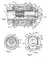
- sheave assembly 10 is shown mounted on a tubular axle 12 in Figure 1.
- sheave assembly 10 includes inner and outer ball bearing races 14 and 16 that are pressed into a sheave body 18 and separated by a spacer 20.
- Sheave 10 also includes inner and outer covers 22 and 24 and inner and outer bearing seals 26 and 28, all of which act to exclude dirt and ice from the bearings 14 and 16.
- One end 30 of axle 12 extends from rocker arm means 32 which attaches the sheave to a tower (not shown). Further details of the design and function of the sheave assembly are contained in my copending application Serial Number 371,526 filed April 26, 1982 and entitled "Sheave Assembly and Method of Forming the Same,. which are hereby incorporated by reference.
- Sheave 10 is mounted on axle 12 by axially sliding the bearings 14 and 16 of the sheave assembly onto the open end 30 of the axle until seal 26 contacts the rocker arm 32. Sheave 10 is axially retained by the rocker arm on the inner side and by a cap means 34 on the outer side of the sheave. Cap means 34 is formed for removable mounting on end 30 of axle 12 by fastener means such as a bolt 36.
- cap means on the end of an axle by a fastener in order to secure a member, such as a sheave assembly, to the axle.
- a fastener in order to secure a member, such as a sheave assembly, to the axle.
- the retention of sheave 10 on axle 12 is accomplished by forming cap means 34 for rotation on the axle about longitudinal axis 44 of the axle and forming the cap with a channel, such as hole 38, through the cap.
- Fastener 36 is mounted to extend through channel or hole 38 and is formed to cooperatively engage a portion of axle 12, in this case a nut 40 welded at 52 to the inside of the tubular axle.
- the retention apparatus is further formed so that one of cap means 34 and axle l2 will wedge between axle l2 and fastener 36 to bind the fastener against removal upon rotation of cap 34 on axle 12.
- cap 34 be disk-shaped and larger in diameter than the axle 12.
- a shoulder or skirt 42 fits over end 30 of the axle to provide positioning of the cap for rotation on the axle. Shoulder 42 also acts to retain sheave 10 on axle 12 by pressing against the outer surface of outer bearing seal 28.
- the hole 38, or channel through the cap, is offset from the axis 44 of the axle by an amount designated by an offset distance 46.
- Nut 40 provides internal thread means for mating with bolt 36 for removably affixing the cap 34 to the axle 12.
- the nut is affixed to the inner wall of the tubular axle by a weld 52, as shown in Figure 3.
- the axis of the nut is concentric to hole 38 and forms a bolt axis 54 that is parallel to axis.44 but offset therefrom by the offset distance 46.
- cap 34 When cap 34 is rotated, therefore, the offset 46 will cause a gradual binding of the cap against bolt 36.
- Other structures suitable for producing such binding would be for shoulder 42 to be inside axle 12.
- hole 38 can be on axis 44 and a cam surface (eccentric) provided on either cap 34 or axle 12 or both.
- sheave assembly 10 When the member being retained on axle 12 is a rotatably mounted member, such as sheave assembly 10, it is advantageous to rotate cap 34 in the direction of rotation of such member. Thus, rotation of sheave assembly 10 will tend to maintain the binding force on bolt 36 and provide a highly effective means of locking the sheave assembly to the wheel.
- Bolt 36 is generaly formed with a shank 56 with external threads 58 at the inner end and a hexagonal head 60 at the outer end. Positioned between the hexagonal head 60 of the bolt and the outer surface of the cap is a washer element or locking plate 62 that provides locking means for locking the bolt to the cap.
- Locking plate 62 is generally rectangular in shape with two square corners 64 and 66 and two notched corners 68 and 70 and has a hole 72 therethrough. As installed, the hole 72 in the locking plate lines up with the hole 38 in the cap 34 for the shank 56 of the bolt to be inserted therethrough.
- the notched corners 68 and 70 of the locking plate fit between stops 48 and 50 protruding from cap 34 to provide antirotation means to prevent rotation of the locking plate relative to the cap.
- square corners 64 and 66 are bent to form tabs 74 and 76 that contact two wrench flats 78 and 80 of the hexagonal head 60.
- the method for retaining a member on an axle of the present invention includes mounting sheave 10 on axle 12 and pushing it inward until the inner bearing seal 26 contacts the rocker arm 32.
- cap 34 is placed over the outer end 30 of the axle and secured.
- either cap 34 or axle 12 is selected to have an eccentric surface, for example hole 38, to longitudinal axis 44 of the axle.
- a locking plate 62 is placed on the cap with the notched corners 68 and 70 fitting between stops 48 and 50 and with hole 72 of the locking plate aligning with hole 38 of the cap prior to securement of the cap to the axle. Corners 64 and 66 are bent up to form tabs 74 and 76 to lock the bolt in place. Removal of the sheave is easily accomplished by reversing the above listed steps.
Landscapes
- Engineering & Computer Science (AREA)
- Transportation (AREA)
- Mechanical Engineering (AREA)
- Pulleys (AREA)
- Bolts, Nuts, And Washers (AREA)
Applications Claiming Priority (2)
| Application Number | Priority Date | Filing Date | Title |
|---|---|---|---|
| US50714283A | 1983-06-23 | 1983-06-23 | |
| US507142 | 1983-06-23 |
Publications (2)
| Publication Number | Publication Date |
|---|---|
| EP0129957A2 true EP0129957A2 (de) | 1985-01-02 |
| EP0129957A3 EP0129957A3 (de) | 1986-04-16 |
Family
ID=24017426
Family Applications (1)
| Application Number | Title | Priority Date | Filing Date |
|---|---|---|---|
| EP84302163A Withdrawn EP0129957A3 (de) | 1983-06-23 | 1984-03-29 | Apparat und Verfahren zur Sicherung von Kabelträgerrollen |
Country Status (2)
| Country | Link |
|---|---|
| EP (1) | EP0129957A3 (de) |
| JP (1) | JPS604612A (de) |
Cited By (1)
| Publication number | Priority date | Publication date | Assignee | Title |
|---|---|---|---|---|
| FR2916718A1 (fr) * | 2007-06-04 | 2008-12-05 | Pomagalski Sa | Dispositif mecanique de reglage d'un balancier d'appui et de guidage d'un cable aerien d'une installation de remontee mecanique |
Family Cites Families (3)
| Publication number | Priority date | Publication date | Assignee | Title |
|---|---|---|---|---|
| DE245356C (de) * | ||||
| GB1004880A (en) * | 1963-01-31 | 1965-09-15 | Scharf Gmbh Heinrich | A pulley for cable guidance |
| US4632597A (en) * | 1982-05-19 | 1986-12-30 | Allsop, Inc. | Releasable locking assembly |
-
1984
- 1984-03-29 EP EP84302163A patent/EP0129957A3/de not_active Withdrawn
- 1984-04-12 JP JP7191984A patent/JPS604612A/ja active Pending
Cited By (2)
| Publication number | Priority date | Publication date | Assignee | Title |
|---|---|---|---|---|
| FR2916718A1 (fr) * | 2007-06-04 | 2008-12-05 | Pomagalski Sa | Dispositif mecanique de reglage d'un balancier d'appui et de guidage d'un cable aerien d'une installation de remontee mecanique |
| EP2014532A1 (de) * | 2007-06-04 | 2009-01-14 | Pomagalski | Mechanische Reguliervorrichtung für einen Stütz- und Führungsausleger des Kabels einer Luftseilbahn |
Also Published As
| Publication number | Publication date |
|---|---|
| EP0129957A3 (de) | 1986-04-16 |
| JPS604612A (ja) | 1985-01-11 |
Similar Documents
| Publication | Publication Date | Title |
|---|---|---|
| CA1124115A (en) | Fastener | |
| US7927052B1 (en) | Locking axle nut | |
| EP0114465B1 (de) | Sicherung für Schraubenverbindung | |
| EP1997955B1 (de) | Fluid-betriebenes Drehmomentwerkzeug und Verfahren zum Festziehen einer Mutter auf einer Platte an Eisenbahnkreuzungen | |
| US8590429B2 (en) | Torque limiting socket and method of using same | |
| RU2530385C2 (ru) | Стопорное устройство для резьбовых крепежных элементов | |
| US20020121805A1 (en) | Apparatus and method for attaching a wheel to an axle | |
| JP4259688B2 (ja) | ボルト・ナットの緩み止め構造 | |
| US5199137A (en) | Rope guard assembly for wedge clamp | |
| EP0129957A2 (de) | Apparat und Verfahren zur Sicherung von Kabelträgerrollen | |
| WO2017020870A1 (zh) | 一种车轮 | |
| CA2129401C (en) | Split stud ring anchoring device | |
| US11084324B2 (en) | Safety restraint for break-away wheel assemblies | |
| JP3004331U (ja) | 転てつ器操作部材の調整装置 | |
| CN112460126A (zh) | 一种防脱螺纹紧固件以及铁路车辆 | |
| CN211006176U (zh) | 一种铁轨用光纤光栅传感器安装固定装置 | |
| CN214116100U (zh) | 一种轨道弹条及轨道扣件组件 | |
| CA1158696A (en) | Roller side bearing mounting system and method | |
| US4355567A (en) | Pivoted blade damper and pin | |
| EP0251545A1 (de) | Bremsanordnung | |
| US11255368B2 (en) | Lock tight bolt-nut | |
| CN113983058A (zh) | 一种防松防滑预埋槽道连接组件 | |
| EP3730357B1 (de) | Rotationsbeschränkungsmechanismus für die wartung | |
| US4393787A (en) | Roller side bearing mounting system and method | |
| EP1534963B1 (de) | Vorrichtung einer bolzen- und muttersicherheitskupplung |
Legal Events
| Date | Code | Title | Description |
|---|---|---|---|
| PUAI | Public reference made under article 153(3) epc to a published international application that has entered the european phase |
Free format text: ORIGINAL CODE: 0009012 |
|
| AK | Designated contracting states |
Designated state(s): AT CH DE FR IT LI SE |
|
| PUAL | Search report despatched |
Free format text: ORIGINAL CODE: 0009013 |
|
| AK | Designated contracting states |
Kind code of ref document: A3 Designated state(s): AT CH DE FR IT LI SE |
|
| STAA | Information on the status of an ep patent application or granted ep patent |
Free format text: STATUS: THE APPLICATION IS DEEMED TO BE WITHDRAWN |
|
| 18D | Application deemed to be withdrawn |
Effective date: 19861217 |