EP0129957A2 - Sheave retention apparatus and method - Google Patents
Sheave retention apparatus and method Download PDFInfo
- Publication number
- EP0129957A2 EP0129957A2 EP84302163A EP84302163A EP0129957A2 EP 0129957 A2 EP0129957 A2 EP 0129957A2 EP 84302163 A EP84302163 A EP 84302163A EP 84302163 A EP84302163 A EP 84302163A EP 0129957 A2 EP0129957 A2 EP 0129957A2
- Authority
- EP
- European Patent Office
- Prior art keywords
- cap
- axle
- fastener
- bolt
- locking
- Prior art date
- Legal status (The legal status is an assumption and is not a legal conclusion. Google has not performed a legal analysis and makes no representation as to the accuracy of the status listed.)
- Withdrawn
Links
Images
Classifications
-
- B—PERFORMING OPERATIONS; TRANSPORTING
- B61—RAILWAYS
- B61B—RAILWAY SYSTEMS; EQUIPMENT THEREFOR NOT OTHERWISE PROVIDED FOR
- B61B12/00—Component parts, details or accessories not provided for in groups B61B7/00 - B61B11/00
- B61B12/06—Safety devices or measures against cable fracture
-
- B—PERFORMING OPERATIONS; TRANSPORTING
- B61—RAILWAYS
- B61B—RAILWAY SYSTEMS; EQUIPMENT THEREFOR NOT OTHERWISE PROVIDED FOR
- B61B12/00—Component parts, details or accessories not provided for in groups B61B7/00 - B61B11/00
- B61B12/02—Suspension of the load; Guiding means, e.g. wheels; Attaching traction cables
Definitions
- the present invention relates, in general, to apparatus for retaining a member on an axle or the like, and more particularly, relates to apparatus for retaining a wheel or sheave assembly on an axle, including means to prevent removal of the sheave as a result of rotation and/or vibration.
- Aerial tramways such as chairlifts, gondolas, trams, and ski lifts are driven by an endless or reciprocating wire rope which is supported on a plurality of sheaves that in turn are usually supported from towers or similar structures.
- Each sheave is usually formed with a disc-like body having a peripheral groove in which the rope is supported.
- each sheave includes a hub with one or more ball or cylindrical bearing races. The bearings permit the sheave to freely rotate about a stationary axle.
- Another object of the present invention is to provide a sheave retention apparatus and method capable of reliable operation under conditions of vibration, rain, ice, and extremely cold temperatures.
- a further object of the present invention is to provide a sheave retention apparatus having threaded fasteners that are protected from the external environment.
- Still another object of the present invention is to provide a sheave retention apparatus that employs a locking mechanism that reliably locks a threaded fastener in place during operation while permitting release of the fastener during sheave replacement.
- Still a further object of the present invention is to provide a reliable method of retaining and replacing a sheave on an axle.
- the sheave retention apparatus of the present invention includes a cap that fits over the end of an axle to retain a sheave or other member thereon, and a fastener that secures the cap to the axle.
- the improvement in the sheave retention apparatus of the present invention is comprised, briefly, of the cap being formed for rotation about the longitudinal axis of the axle, the fastener being mounted through a channel or opening in the cap to secure the cap against axial displacement, and one of the cap and axle being formed with a surface which is eccentric to the longitudinal axis of the axle so that rotation of the cap with respect to the axle binds the cap between the fastener and the axle.
- the cap is advantageously disk shaped and has a shoulder that fits over the end of the axle.
- the eccentric surface is provided by an off-center hole in the cap, and a fastening bolt passes through the hole and into a corresponding off-center internal thread within the axle.
- the internally threaded member can be provided by a nut welded to the inner wall of the tubular axle.
- Locking means also preferably is provided by employing a locking plate that is clamped between the hexagonal head of the bolt and the outer surface of the cap. The locking plate is formed to prevent relative rotation with respect to the cap and has two square corners that are bent up against the wrench flats of the bolt to prevent the bolt from rotating with respect to the locking plate.
- the improved method of the present invention is comprised, briefly, of securing the cap to the axle by rotating the cap on the axle so as to cause binding of the cap between the axle and the bolt. At least one of the cap and the axle must be selected to have an eccentric surface which will cause such binding.
- sheave assembly 10 is shown mounted on a tubular axle 12 in Figure 1.
- sheave assembly 10 includes inner and outer ball bearing races 14 and 16 that are pressed into a sheave body 18 and separated by a spacer 20.
- Sheave 10 also includes inner and outer covers 22 and 24 and inner and outer bearing seals 26 and 28, all of which act to exclude dirt and ice from the bearings 14 and 16.
- One end 30 of axle 12 extends from rocker arm means 32 which attaches the sheave to a tower (not shown). Further details of the design and function of the sheave assembly are contained in my copending application Serial Number 371,526 filed April 26, 1982 and entitled "Sheave Assembly and Method of Forming the Same,. which are hereby incorporated by reference.
- Sheave 10 is mounted on axle 12 by axially sliding the bearings 14 and 16 of the sheave assembly onto the open end 30 of the axle until seal 26 contacts the rocker arm 32. Sheave 10 is axially retained by the rocker arm on the inner side and by a cap means 34 on the outer side of the sheave. Cap means 34 is formed for removable mounting on end 30 of axle 12 by fastener means such as a bolt 36.
- cap means on the end of an axle by a fastener in order to secure a member, such as a sheave assembly, to the axle.
- a fastener in order to secure a member, such as a sheave assembly, to the axle.
- the retention of sheave 10 on axle 12 is accomplished by forming cap means 34 for rotation on the axle about longitudinal axis 44 of the axle and forming the cap with a channel, such as hole 38, through the cap.
- Fastener 36 is mounted to extend through channel or hole 38 and is formed to cooperatively engage a portion of axle 12, in this case a nut 40 welded at 52 to the inside of the tubular axle.
- the retention apparatus is further formed so that one of cap means 34 and axle l2 will wedge between axle l2 and fastener 36 to bind the fastener against removal upon rotation of cap 34 on axle 12.
- cap 34 be disk-shaped and larger in diameter than the axle 12.
- a shoulder or skirt 42 fits over end 30 of the axle to provide positioning of the cap for rotation on the axle. Shoulder 42 also acts to retain sheave 10 on axle 12 by pressing against the outer surface of outer bearing seal 28.
- the hole 38, or channel through the cap, is offset from the axis 44 of the axle by an amount designated by an offset distance 46.
- Nut 40 provides internal thread means for mating with bolt 36 for removably affixing the cap 34 to the axle 12.
- the nut is affixed to the inner wall of the tubular axle by a weld 52, as shown in Figure 3.
- the axis of the nut is concentric to hole 38 and forms a bolt axis 54 that is parallel to axis.44 but offset therefrom by the offset distance 46.
- cap 34 When cap 34 is rotated, therefore, the offset 46 will cause a gradual binding of the cap against bolt 36.
- Other structures suitable for producing such binding would be for shoulder 42 to be inside axle 12.
- hole 38 can be on axis 44 and a cam surface (eccentric) provided on either cap 34 or axle 12 or both.
- sheave assembly 10 When the member being retained on axle 12 is a rotatably mounted member, such as sheave assembly 10, it is advantageous to rotate cap 34 in the direction of rotation of such member. Thus, rotation of sheave assembly 10 will tend to maintain the binding force on bolt 36 and provide a highly effective means of locking the sheave assembly to the wheel.
- Bolt 36 is generaly formed with a shank 56 with external threads 58 at the inner end and a hexagonal head 60 at the outer end. Positioned between the hexagonal head 60 of the bolt and the outer surface of the cap is a washer element or locking plate 62 that provides locking means for locking the bolt to the cap.
- Locking plate 62 is generally rectangular in shape with two square corners 64 and 66 and two notched corners 68 and 70 and has a hole 72 therethrough. As installed, the hole 72 in the locking plate lines up with the hole 38 in the cap 34 for the shank 56 of the bolt to be inserted therethrough.
- the notched corners 68 and 70 of the locking plate fit between stops 48 and 50 protruding from cap 34 to provide antirotation means to prevent rotation of the locking plate relative to the cap.
- square corners 64 and 66 are bent to form tabs 74 and 76 that contact two wrench flats 78 and 80 of the hexagonal head 60.
- the method for retaining a member on an axle of the present invention includes mounting sheave 10 on axle 12 and pushing it inward until the inner bearing seal 26 contacts the rocker arm 32.
- cap 34 is placed over the outer end 30 of the axle and secured.
- either cap 34 or axle 12 is selected to have an eccentric surface, for example hole 38, to longitudinal axis 44 of the axle.
- a locking plate 62 is placed on the cap with the notched corners 68 and 70 fitting between stops 48 and 50 and with hole 72 of the locking plate aligning with hole 38 of the cap prior to securement of the cap to the axle. Corners 64 and 66 are bent up to form tabs 74 and 76 to lock the bolt in place. Removal of the sheave is easily accomplished by reversing the above listed steps.
Landscapes
- Engineering & Computer Science (AREA)
- Transportation (AREA)
- Mechanical Engineering (AREA)
- Pulleys (AREA)
- Bolts, Nuts, And Washers (AREA)
Abstract
@ The sheave retention apparatus of the present invention includes a cap (34) that fits over the end (30) of an axle (12) to retain a sheave (10) thereon. A bolt (36) fastens the cap to the axle. Cap (34) is disk shaped with a shoulder (42) that fits over end (30) of axle (12). When installed, bolt (36) passes through an off-center hold (38) in the cap and into a corresponding off-center nut (40) welded to the inner wall of the tubular axle. Rotation of cap (34) on axle (12) will bind the cap between the bolt and the axle to prevent unthreading of the bolt. Additionally, to resist unthreading under vibrational influences, a locking plate (62) that is clamped between the hexagonal head (60) of the bolt and the outer surface of the cap. The locking plate has two notched corners (68) and (70) that contact a portion of the cap to prevent rotation of the locking plate with respect to the cap, and has two square comers (64) and (66) that are bent up against the wrench flats of the bolt to prevent the bolt from rotating with respect to the locking plate.
Description
- This application is a continuation-in-part application based upon prior copending application Serial No. 371,526 filed April 26, 1982, and entitled "Sheave Assembly and Method of Forming the Same."
- The present invention relates, in general, to apparatus for retaining a member on an axle or the like, and more particularly, relates to apparatus for retaining a wheel or sheave assembly on an axle, including means to prevent removal of the sheave as a result of rotation and/or vibration.
- Aerial tramways, such as chairlifts, gondolas, trams, and ski lifts are driven by an endless or reciprocating wire rope which is supported on a plurality of sheaves that in turn are usually supported from towers or similar structures. Each sheave is usually formed with a disc-like body having a peripheral groove in which the rope is supported. Typically, each sheave includes a hub with one or more ball or cylindrical bearing races. The bearings permit the sheave to freely rotate about a stationary axle.
- There are several operational considerations with respect to the method of retaining a sheave or wheel on its axle. Since the main purpose of.an aerial tramway is to transport skiers or other passengers, the failure to properly retain sheaves can lead to life threatening situations. Operational reliability is the primary consideration in the evaluation of retention methods. Although gangs of several sheaves are commonly utilized at each tower to minimize risk, the failure to retain a sheave could allow it to jam the other sheaves or to fall and injure skiers or passengers below. Vibrations caused by the sheaves and the wire rope motion tend to loosen commonly available threaded fasteners. The harsh operating environment exposes the sheaves to conditions of water, ice, and extremely cold temperatures. Replacement of sheaves under all operating conditions must be accommodated without endangering the safety of maintenance personnel. In short, the sheaves must be reliably retained but easily replaceable under the harsh operating environment typically encountered.
- Commonly used methods of retaining wheels on axles may not be appropriate in this harsh operating environment. One method using an externally threaded axle and locking nut to retain the sheave would experience corrosion problems on exposed threads and, therefore, would not allow easy sheave replacement. Other methods using adhesives to prevent threaded fasteners from loosening would not operate reliably in wet or cold weather. Fastener locking using removable pins would suffer from corrosion and replaceability problems and high manufacturing expense.
- Accordingly, it is an object of the present invention to provide a sheave retention apparatus and method that is capable of reliably retaining a sheave on an axle while facilitating removal for replacement.
- Another object of the present invention is to provide a sheave retention apparatus and method capable of reliable operation under conditions of vibration, rain, ice, and extremely cold temperatures.
- A further object of the present invention is to provide a sheave retention apparatus having threaded fasteners that are protected from the external environment.
- Still another object of the present invention is to provide a sheave retention apparatus that employs a locking mechanism that reliably locks a threaded fastener in place during operation while permitting release of the fastener during sheave replacement.
- Still a further object of the present invention is to provide a reliable method of retaining and replacing a sheave on an axle.
- The sheave retention apparatus and method of the present invention have other objects and features of advantage which will become apparent from and are set forth in more detail in the accompanying drawing and the following description of the preferred embodiment.
- The sheave retention apparatus of the present invention includes a cap that fits over the end of an axle to retain a sheave or other member thereon, and a fastener that secures the cap to the axle. The improvement in the sheave retention apparatus of the present invention is comprised, briefly, of the cap being formed for rotation about the longitudinal axis of the axle, the fastener being mounted through a channel or opening in the cap to secure the cap against axial displacement, and one of the cap and axle being formed with a surface which is eccentric to the longitudinal axis of the axle so that rotation of the cap with respect to the axle binds the cap between the fastener and the axle. The cap is advantageously disk shaped and has a shoulder that fits over the end of the axle. Preferably the eccentric surface is provided by an off-center hole in the cap, and a fastening bolt passes through the hole and into a corresponding off-center internal thread within the axle. The internally threaded member can be provided by a nut welded to the inner wall of the tubular axle. Locking means also preferably is provided by employing a locking plate that is clamped between the hexagonal head of the bolt and the outer surface of the cap. The locking plate is formed to prevent relative rotation with respect to the cap and has two square corners that are bent up against the wrench flats of the bolt to prevent the bolt from rotating with respect to the locking plate.
- The improved method of the present invention, is comprised, briefly, of securing the cap to the axle by rotating the cap on the axle so as to cause binding of the cap between the axle and the bolt. At least one of the cap and the axle must be selected to have an eccentric surface which will cause such binding.
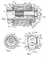
- Figure 1 is a side elevational view in cross- section along the axis of an installed sheave retention apparatus constructed according to the present invention.
- Figure 2 is an end elevational view of the retention apparatus of Figure 1.
- Figure 3 is a cross-sectional view of an interior portion of the retention apparatus taken substantially along the plane of line 3-3 in Figure 1,
- A sheave assembly, generally designated 10, is shown mounted on a
tubular axle 12 in Figure 1. Briefly,sheave assembly 10 includes inner and outer ball bearingraces sheave body 18 and separated by aspacer 20. Sheave 10 also includes inner andouter covers outer bearing seals bearings end 30 ofaxle 12 extends from rocker arm means 32 which attaches the sheave to a tower (not shown). Further details of the design and function of the sheave assembly are contained in my copending application Serial Number 371,526 filed April 26, 1982 and entitled "Sheave Assembly and Method of Forming the Same,. which are hereby incorporated by reference. - Sheave 10 is mounted on
axle 12 by axially sliding thebearings open end 30 of the axle untilseal 26 contacts therocker arm 32. Sheave 10 is axially retained by the rocker arm on the inner side and by a cap means 34 on the outer side of the sheave.Cap means 34 is formed for removable mounting onend 30 ofaxle 12 by fastener means such as abolt 36. - Broadly it is known to mount cap means on the end of an axle by a fastener in order to secure a member, such as a sheave assembly, to the axle. In the improved retention apparatus of the present invention, however, the retention of
sheave 10 onaxle 12 is accomplished by forming cap means 34 for rotation on the axle about longitudinal axis 44 of the axle and forming the cap with a channel, such as hole 38, through the cap.Fastener 36 is mounted to extend through channel or hole 38 and is formed to cooperatively engage a portion ofaxle 12, in this case anut 40 welded at 52 to the inside of the tubular axle. - In order to secure the fastening bolt against unthreading, the retention apparatus is further formed so that one of cap means 34 and axle l2 will wedge between axle l2 and fastener 36 to bind the fastener against removal upon rotation of
cap 34 onaxle 12. - Binding of the cap between the bolt and the axle can be accomplished in a number of ways. It is preferable that
cap 34 be disk-shaped and larger in diameter than theaxle 12. A shoulder orskirt 42 fits overend 30 of the axle to provide positioning of the cap for rotation on the axle.Shoulder 42 also acts to retainsheave 10 onaxle 12 by pressing against the outer surface ofouter bearing seal 28. The hole 38, or channel through the cap, is offset from the axis 44 of the axle by an amount designated by anoffset distance 46. -
Nut 40 provides internal thread means for mating withbolt 36 for removably affixing thecap 34 to theaxle 12. The nut is affixed to the inner wall of the tubular axle by aweld 52, as shown in Figure 3. The axis of the nut is concentric to hole 38 and forms abolt axis 54 that is parallel to axis.44 but offset therefrom by theoffset distance 46. - When
cap 34 is rotated, therefore, theoffset 46 will cause a gradual binding of the cap againstbolt 36. Other structures suitable for producing such binding would be forshoulder 42 to be insideaxle 12. Alternatively, hole 38 can be on axis 44 and a cam surface (eccentric) provided on eithercap 34 oraxle 12 or both. - When the member being retained on
axle 12 is a rotatably mounted member, such assheave assembly 10, it is advantageous to rotatecap 34 in the direction of rotation of such member. Thus, rotation ofsheave assembly 10 will tend to maintain the binding force onbolt 36 and provide a highly effective means of locking the sheave assembly to the wheel. - Since in many application, including aerial tramways, the axle will experience vibration, it is preferable to provide means which will prevent the fastener or bolt from backing out of the nut under the influence of vibrations if, for some reason, the cap is not binding the bolt against rotation.
-
Bolt 36 is generaly formed with ashank 56 withexternal threads 58 at the inner end and ahexagonal head 60 at the outer end. Positioned between thehexagonal head 60 of the bolt and the outer surface of the cap is a washer element orlocking plate 62 that provides locking means for locking the bolt to the cap.Locking plate 62 is generally rectangular in shape with twosquare corners 64 and 66 and twonotched corners hole 72 therethrough. As installed, thehole 72 in the locking plate lines up with the hole 38 in thecap 34 for theshank 56 of the bolt to be inserted therethrough. The notchedcorners stops cap 34 to provide antirotation means to prevent rotation of the locking plate relative to the cap. To lock the bolt to the locking plate,square corners 64 and 66 are bent to formtabs wrench flats hexagonal head 60. - Although the
cap 34 by itself is free to rotate about axis 44,bolt 36 prevents the cap fom rotating because hole 38 is offset from axis 44. By locking the bolt to lockingplate 62 and to cap 34, the retention apparatus is completely locked in place. If thebolt axis 54 were coincident with the axle axis 44, locking the bolt to the cap would not lock the apparatus because the whole assembly could rotate and allow the bolt to loosen. However, by offsetting the two axes, the bolt and the cap act to lock each other in place. - The method for retaining a member on an axle of the present invention includes mounting
sheave 10 onaxle 12 and pushing it inward until theinner bearing seal 26 contacts therocker arm 32. Next,cap 34 is placed over theouter end 30 of the axle and secured. In the improved method, however, eithercap 34 oraxle 12 is selected to have an eccentric surface, for example hole 38, to longitudinal axis 44 of the axle. Preferably a lockingplate 62 is placed on the cap with the notchedcorners stops hole 72 of the locking plate aligning with hole 38 of the cap prior to securement of the cap to the axle.Corners 64 and 66 are bent up to formtabs
Claims (20)
1. A retention apparatus for the removable mounting of a member to axle means or the like, said apparatus including cap means (34) formed for mounting on an end (30) of said axle means (12), and fastener means (36) formed to secure said cap means to said end of said axle means, wherein the improvement in said retainer apparatus comprises:
said cap means (34) being further formed for rotation about the longitudinal axis (44) of said axle means (12) and being formed with a channel (38) extending longitudinally therethrough;
said fastener means (36) being mounted to extend through said channel and formed to cooperatively engage said axle means for removable securement of said cap means against axial displacement; and
one of said cap means (34) and said axle means (12) being further formed to wedge between said axle means and said fastener means to bind said fastener means against removal upon rotation of said cap means with respect to said axle.
2. The retention apparatus as defined in claim 1 wherein,
said fastener means (36) and said axle means (12) are formed for cooperative threaded engagement; and
said channel is positioned in said cap means (34) at a location (54) offset with respect to said (44) axis to bind said fastener means (36) against unthreading upon rotation of said cap means (34).
3. The retention apparatus as defined in claim 2 wherein,
said fastener means (36) is provided as a bolt having a head portion (60), a shank portion (56) and a threaded end (58);
said axle means includes a threaded element (40) formed for mating threaded engagement with said threaded end (58); and
said cap means (34) is formed for binding against said shank portion (56).
4. The retention apparatus as defined in claim 3 wherein,
said axle means (12) includes an axially extending bore dimensioned to receive said bolt (36) and positioned in substantial alignment with said channel (38) upon mounting of said cap means (34) on said axle;
said threaded end (58) is provided as an external thread on said bolt; and
said threaded element (40) is provided as an internal thread.
5. The retention apparatus as defined in claim 4, and
locking means (62) formed for selective locking and release of said head portion (60) against relative rotation with respect to said cap means (34).
locking means (62) formed for selective locking and release of said head portion (60) against relative rotation with respect to said cap means (34).
6. The retention apparatus as defined in claim 5 wherein,
said locking means (62) is provided as a washer element mounted between said head portion (60) and said cap means (34) and formed with a peripheral edge portion (64, 66, 68, 70) which can be selectively engaged with a surface on said head portion (78, 80) and a surface (48, 50) on said cap means to prevent relative rotation thereof.
said locking means (62) is provided as a washer element mounted between said head portion (60) and said cap means (34) and formed with a peripheral edge portion (64, 66, 68, 70) which can be selectively engaged with a surface on said head portion (78, 80) and a surface (48, 50) on said cap means to prevent relative rotation thereof.
7. The retention apparatus as defined in claim 1, and
locking means (62) formed for selective locking and release of said cap means (34) and said fastener means (36) against relative rotation.
locking means (62) formed for selective locking and release of said cap means (34) and said fastener means (36) against relative rotation.
8. Apparatus for removably retaining a sheave assembly (10) on an axle including a cap (34) removably affixed to one end (30) of the axle (12) by a threaded fastener (36), wherein the improvement in said apparatus is comprised of:
thread means (40) secured to said axle and formed for mating with said threaded fastener;
said cap having a perforation (38) therethrough;
said threaded fastener (36) disposed through said perforation and threadably engaged with said thread means (40) and retaining said cap against said end (30) of said axle (12); and
at least one of said axle (12) and said cap (34) being further formed to produce binding of said cap between said axle and said fastener (36) upon rotation of said cap about the longitudinal axis (44) of said axle (16).
9. Apparatus as defined in claim 8 wherein,
said cap (34) and said axle (12) are formed with complementary bearing surfaces extending along said longitudinal axis (44) of said axle (12) and formed for guided rotation of said cap with respect to said axle; and
at least one of said surfaces and said perforation (38) is relatively displaced with respect to said axis (44) to produce said binding.
10. Apparatus as defined in claim 9 wherein, said surfaces are mating substantially cylindrical surfaces positioned substantially concentrically with said axis (44), and
said perforation (38) is laterally offset with respect to said axis (44).
said perforation (38) is laterally offset with respect to said axis (44).
ll. Apparatus as defined in claim 10 wherein,
said cap (34) is formed with a skirt (42) which extends around the exterior of said axle (12) and provides the bearing surface on said cap.
said cap (34) is formed with a skirt (42) which extends around the exterior of said axle (12) and provides the bearing surface on said cap.
12. The apparatus as defined in claim 8, and locking means (62) formed for locking said threaded fastener (36) to said cap (34).
13. Apparatus as defined in claim-12 wherein,
said threaded fastener (36) includes a shank portion (56), external threads (58) at one end of said shank portion for engaging said internal thread means (40), and a head portion (60) at the end opposite said external threads; and
said locking means (62) is operable for engaging said head portion (60) of said threaded fastener (36) to prevent rotation of said threaded fastener with respect to said cap.
14. Apparatus as defined in claim 13 wherein,
said head portion (60) of said threaded fastener (36) is formed with at least one surface (78, 80) against which a torque may be applied to rotate said threaded fastener; and
said locking means (62) includes a locking plate disposed between said cap (34) and said head portion (60) of said threaded fastener (36), said locking plate has at least one tab (74, 76) formed for contacting said surface (78, 80), and said locking means (62) also includes antirotation means (68, 70) for preventing rotation of said locking plate with respect to said cap.
15. Apparatus as defined in claim 14 wherein,
said threaded fastener (36) is disposed through a hole (72) in said locking plate; and
said antirotation means includes stop means (48, 50) formed in said cap (34) and positioned to contact said locking plate (62) and formed to prevent rotation thereof.
said threaded fastener (36) is disposed through a hole (72) in said locking plate; and
said antirotation means includes stop means (48, 50) formed in said cap (34) and positioned to contact said locking plate (62) and formed to prevent rotation thereof.
16. ,Apparatus as defined in claim 15 wherein,
said surface is provided by wrench flats (78, 80) formed on said head portion (60);
said locking plate (62) is formed with at least one notch (68, 70) in the periphery thereof; and
said stop means (48, 50) is formed as a protrusion dimensioned for insertion into said notch (68, 70) and extending outwardly of said cap (34) into said notch (68, 70) when said plate (62) is mounted between said cap (34) and said head portion (60).
17. Apparatus as defined in claim 8 wherein,
said axle (12) is tubular in shape with said sheave assembly (10) being retained on the external surface thereof; and
said internal thread means (40) is a nut having internal threads, said nut being affixed to the internal surface of said tubular axle.
18. A method of retaining a member on axle means (12) or the like including the step of securing cap means (34) to the end (30) of said axle means, wherein the improvement in said method is comprised of:
prior to said securing step, selecting at least one of cap means and axle means to have an eccentric surface wih respect to the longitudinal axis of said axle means; and
during said securing step:
(i) mounting said cap means (34) to said axle means (12) for engagement of said eccentric surface with one of said fastener and a remainder of said cap means and said axle means,
(ii) coupling said cap means (34) to said axle means (12) by fastener means (36) extending in a direction along said longitudinal axis and secured to said axle means, and
(iii) after said coupling step, rotating said cap means (34) about said longitudinal axis to bind said cap means between said fastener means (36) and said axle means (34).
19. The method of retaining a member on axle means as defined in claim 18, and the additional steps of:
prior to said mounting step, placing sheave assembly on one end (30) of said axle means;
during said selecting step, selecting cap means (34) having an off-center hole (38) therethrough;
during said coupling step, installing a bolt fastener (36) through said hole (38) and threading said bolt into an off-center threaded hole in said axle means; and
locking said bolt (36) to said cap means (34) to prevent rotation of said bolt with respect to said cap means.
20. The method of retaining a member on axle means as defined in claim 19, and the step of:
installing a locking plate (62) over said cap means (34) before said bolt (36) is installed, said locking plate (62) being formed to engage said cap means (34) in a manner preventing relative rotation; and
bending a portion of said locking plate to lock said bolt thereto.
Applications Claiming Priority (2)
| Application Number | Priority Date | Filing Date | Title |
|---|---|---|---|
| US50714283A | 1983-06-23 | 1983-06-23 | |
| US507142 | 2000-02-18 |
Publications (2)
| Publication Number | Publication Date |
|---|---|
| EP0129957A2 true EP0129957A2 (en) | 1985-01-02 |
| EP0129957A3 EP0129957A3 (en) | 1986-04-16 |
Family
ID=24017426
Family Applications (1)
| Application Number | Title | Priority Date | Filing Date |
|---|---|---|---|
| EP84302163A Withdrawn EP0129957A3 (en) | 1983-06-23 | 1984-03-29 | Sheave retention apparatus and method |
Country Status (2)
| Country | Link |
|---|---|
| EP (1) | EP0129957A3 (en) |
| JP (1) | JPS604612A (en) |
Cited By (1)
| Publication number | Priority date | Publication date | Assignee | Title |
|---|---|---|---|---|
| FR2916718A1 (en) * | 2007-06-04 | 2008-12-05 | Pomagalski Sa | MECHANICAL DEVICE FOR ADJUSTING A SUPPORT AND GUIDING BALANCE FOR AN AIR CABLE OF A MECHANICAL REASSEMBLY SYSTEM |
Citations (3)
| Publication number | Priority date | Publication date | Assignee | Title |
|---|---|---|---|---|
| DE245356C (en) * | ||||
| GB1004880A (en) * | 1963-01-31 | 1965-09-15 | Scharf Gmbh Heinrich | A pulley for cable guidance |
| GB2120314A (en) * | 1982-05-19 | 1983-11-30 | Allsop Inc | Adjustable support assembly for musical instrument |
-
1984
- 1984-03-29 EP EP84302163A patent/EP0129957A3/en not_active Withdrawn
- 1984-04-12 JP JP7191984A patent/JPS604612A/en active Pending
Patent Citations (3)
| Publication number | Priority date | Publication date | Assignee | Title |
|---|---|---|---|---|
| DE245356C (en) * | ||||
| GB1004880A (en) * | 1963-01-31 | 1965-09-15 | Scharf Gmbh Heinrich | A pulley for cable guidance |
| GB2120314A (en) * | 1982-05-19 | 1983-11-30 | Allsop Inc | Adjustable support assembly for musical instrument |
Cited By (2)
| Publication number | Priority date | Publication date | Assignee | Title |
|---|---|---|---|---|
| FR2916718A1 (en) * | 2007-06-04 | 2008-12-05 | Pomagalski Sa | MECHANICAL DEVICE FOR ADJUSTING A SUPPORT AND GUIDING BALANCE FOR AN AIR CABLE OF A MECHANICAL REASSEMBLY SYSTEM |
| EP2014532A1 (en) * | 2007-06-04 | 2009-01-14 | Pomagalski | Mechanical device for adjusting the rocker arm supporting and guiding the cable of an aerial cableway |
Also Published As
| Publication number | Publication date |
|---|---|
| JPS604612A (en) | 1985-01-11 |
| EP0129957A3 (en) | 1986-04-16 |
Similar Documents
| Publication | Publication Date | Title |
|---|---|---|
| CA1124115A (en) | Fastener | |
| EP0114465B1 (en) | Screw-action connectors security means | |
| EP1997955B1 (en) | A fluid operated torque tool for and a method of tightening a nut on a plate on railroad crossings | |
| US8590429B2 (en) | Torque limiting socket and method of using same | |
| US6598941B2 (en) | Apparatus and method for attaching a wheel to an axle | |
| JP4259688B2 (en) | Bolt / nut locking structure | |
| US5199137A (en) | Rope guard assembly for wedge clamp | |
| US4478458A (en) | Locking and anti-loosening construction for vehicle rim | |
| EP0129957A2 (en) | Sheave retention apparatus and method | |
| CA2129401C (en) | Split stud ring anchoring device | |
| KR100398934B1 (en) | Nuts having a spring for restraining loose | |
| GB2132301A (en) | Screw-action connectors security means | |
| US11255368B2 (en) | Lock tight bolt-nut | |
| JP3004331U (en) | Adjusting device for operating device | |
| CA1158696A (en) | Roller side bearing mounting system and method | |
| CN112442925A (en) | Track elastic strip and track fastener assembly | |
| US11084324B2 (en) | Safety restraint for break-away wheel assemblies | |
| EP0251545A1 (en) | Brake assemblies | |
| CN214116100U (en) | Track elastic strip and track fastener assembly | |
| CN112460126B (en) | Anticreep threaded fastener and rail vehicle | |
| US4393787A (en) | Roller side bearing mounting system and method | |
| JPH06249222A (en) | Locking fixture and tool therefor | |
| JPS6042109Y2 (en) | Mooring device | |
| EP1534963B1 (en) | Safety nut and bolt clutch assembly | |
| CN217234096U (en) | Bolt for automobile hub |
Legal Events
| Date | Code | Title | Description |
|---|---|---|---|
| PUAI | Public reference made under article 153(3) epc to a published international application that has entered the european phase |
Free format text: ORIGINAL CODE: 0009012 |
|
| AK | Designated contracting states |
Designated state(s): AT CH DE FR IT LI SE |
|
| PUAL | Search report despatched |
Free format text: ORIGINAL CODE: 0009013 |
|
| AK | Designated contracting states |
Kind code of ref document: A3 Designated state(s): AT CH DE FR IT LI SE |
|
| STAA | Information on the status of an ep patent application or granted ep patent |
Free format text: STATUS: THE APPLICATION IS DEEMED TO BE WITHDRAWN |
|
| 18D | Application deemed to be withdrawn |
Effective date: 19861217 |