EP0251545A1 - Brake assemblies - Google Patents
Brake assemblies Download PDFInfo
- Publication number
- EP0251545A1 EP0251545A1 EP87305287A EP87305287A EP0251545A1 EP 0251545 A1 EP0251545 A1 EP 0251545A1 EP 87305287 A EP87305287 A EP 87305287A EP 87305287 A EP87305287 A EP 87305287A EP 0251545 A1 EP0251545 A1 EP 0251545A1
- Authority
- EP
- European Patent Office
- Prior art keywords
- platform
- gusset
- screw
- brake shoe
- mounting
- Prior art date
- Legal status (The legal status is an assumption and is not a legal conclusion. Google has not performed a legal analysis and makes no representation as to the accuracy of the status listed.)
- Withdrawn
Links
Images


Classifications
-
- F—MECHANICAL ENGINEERING; LIGHTING; HEATING; WEAPONS; BLASTING
- F16—ENGINEERING ELEMENTS AND UNITS; GENERAL MEASURES FOR PRODUCING AND MAINTAINING EFFECTIVE FUNCTIONING OF MACHINES OR INSTALLATIONS; THERMAL INSULATION IN GENERAL
- F16D—COUPLINGS FOR TRANSMITTING ROTATION; CLUTCHES; BRAKES
- F16D65/00—Parts or details
- F16D65/02—Braking members; Mounting thereof
- F16D65/04—Bands, shoes or pads; Pivots or supporting members therefor
- F16D65/08—Bands, shoes or pads; Pivots or supporting members therefor for internally-engaging brakes
-
- F—MECHANICAL ENGINEERING; LIGHTING; HEATING; WEAPONS; BLASTING
- F16—ENGINEERING ELEMENTS AND UNITS; GENERAL MEASURES FOR PRODUCING AND MAINTAINING EFFECTIVE FUNCTIONING OF MACHINES OR INSTALLATIONS; THERMAL INSULATION IN GENERAL
- F16D—COUPLINGS FOR TRANSMITTING ROTATION; CLUTCHES; BRAKES
- F16D69/00—Friction linings; Attachment thereof; Selection of coacting friction substances or surfaces
- F16D2069/004—Profiled friction surfaces, e.g. grooves, dimples
Definitions
- This invention relates to brake assemblies of the internal expanding shoe and drum type wherein the brake shoes have at least one gusset or web, such as are used on heavy vehicles.
- Conventional shoe and drum type brakes require removal of the brake drum for access to the brake for replacement of worn friction linings.
- the wheel has to be removed to allow removal of the brake drum and the brake shoes have to be removed to be re-lined with linings of friction material or replaced by ready lined service brake shoes.
- This invention is directed to facilitating the replacement of friction linings of internal expanding shoe and drum type brake assemblies.
- a brake shoe comprising at least one generally arc-shaped gusset and a platform thereon having another face adapted to carry a friction lining, and being characterised in that the gusset and platform are separable components, a mounting is fast with the gusset, the platform has at least one surface which co-operates with the mounting to locate the platform relative to the gusset, and releasable means secure the platform and gusset together in assembled relationship.
- Means may be provided to act between the platform and gusset to cause release, or release and at least partial withdrawal, of the platform from the mounting.
- the mounting may include laterally extending means for guidance and/or location of the platform.
- the mounting preferably locates the platform longitudinally of the gusset.
- gussets There may be more than one gusset.
- two generally arc-shaped gussets may be joined together in laterally spaced relationship whereon the mounting is provided.
- the platform may be generally arc-shaped.
- the releaseable means may secure the platform to one gusset or to both gussets.
- Co-operating means on the or each gusset and the platform may be provided whereby the platform is removably received and located on the convex face of the gusset or gussets.
- Means may be provided to locate the platform laterally relative to the gusset or gussets.
- Means may be provided to facilitate insertion of a platform into the mounting.
- the invention also comprises a brake assembly including brake shoes in accordance with the first aspect of the invention set out herein.
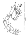
- each gusset has a semi-circular cut-out 5 to receive a cam roller for brake operation by a conventional S cam. Also at that end are holes 6 which provide locations for a cam roller retainer and holes 7 to provide an anchorage for a brake release spring.
- the other end of each gusset has a slot 8 to receive a brake anchor pin, such as is described in British Patent No. 1 580 963 of Rockwell International Corporation. Holes 9 provide an anchorage for a retaining spring.
- each gusset 1, 2 intermediate its ends has a recess 11, 12, the recesses being in alignment and having their ends inwardly inclined as shown in Figure 1.
- An arcuately shaped platform 13, generally rectangular in plan view, has bevelled edges 14, 15 inclined complementally to the inwardly inclined ends of the recesses 11, 12 whereby the platform can be inserted into the recesses and located and retained by their interengagement with the inwardly inclined ends of the recesses.
- the platform 13 has a downwardly depending lug 16 which locates against one gusset 2 when the platform is assembled to the gussets, locating the platform transversely of the gussets.
- a hole 17 in the lug 16 registers with a screw-threaded hole 18 in that gusset 2 and the assembly is secured with a wing screw 19.
- a friction lining 21 is secured to the platform 13 on its convex face, as by bonding or riveting.
- the convex faces of the recesses 11, 12 may be relieved to allow clearance for rivet ends protruding from the concave face of the platform 13.
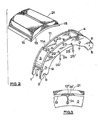
- the brake shoe has gussets and a platform which are similar to those described with reference to Figure 1, the same reference numerals being used to identify corresponding parts of the brake shoe.
- the platform 13 does not have a lug 16.
- Aligned holes 22, 23 in the gussets 1, 2 accommodate spring clips 24, 25.
- the concave face of the platform 13 is provided with locating slots 13' which, when the platform is correctly assembled to the gussets, are aligned with the similar, cranked ends 24', 25' of the spring clips 24, 25.
- the assembly is secured by rotating the clips so that their ends 24' 25' engage in the slots 13' in the platform 13, as seen in Figure 3.
- the brake shoe assembly of Figure 1 can be dis-assembled from one side by removal of the wing screw 19 and withdrawal of the platform 13 when the lining 21 is worn. A replacement lined platform 13 can then be fitted in the manner described. There is thus no need to remove the gusset assembly, as has to be done with conventional brake shoes.
- the lug 16 may be extended (as shown in broken lines) and provided with a screw-threaded hole 16' at each side of the hole 17. In the event that the platform 13 is fast in its mounting, screws can be inserted in these additional holes 16' and can be used to react against the adjacent gusset 2 to release the platform 13 and assist in its removal from the recesses 11, 12.
- a withdrawal tool as 35, illustrated in Figure 4
- Such a tool, as 35, illustrated in Figure 4 might have two screw-threaded holes 36, into which screws are inserted to engage and react against the adjacent gusset 1 or 2 and so cause withdrawal, or partial withdrawal, of the platform from the recesses 11, 12.
- screw-threaded holes 18 in the gussets may be used in conjunction with correspondingly screw-threaded members and the lug 16 to cause the platform 13 to be drawn into the recesses.
- the withdrawal tool 35 which has been described may also have plain holes, as 37, whereby, in conjunction with screw-threaded holes in the adjacent gusset 1, 2, it can serve as both an insertion tool and a withdrawal tool.
- the modified platform 13 shown has a lug 26 of generally U-section or L-section, for stiffness, with a screw-threaded hole 26' in which a screw 27 is received.
- the screw 27 has a head 28 of a conventional shape to be engaged by a spanner or drive socket, a threaded shank 29 and a plain extension 31 of reduced diameter.
- the gussets 1, 2 have holes 32 which are in alignment with the screw-threaded hole in the lug 26 and are of a size to allow the extension 31 and shank 29 respectively to pass through with clearance.
- a locking member comprising a lock plate 33 has a screw-threaded hole to receive the shank 29 and a lip 34 to locate under the adjacent gusset 2 so as to prevent rotation of the lock plate.
- the platform 13 is mounted on the gussets 1, 2, is located laterally by abutment of the lug 26 against the adjacent gusset 2, and is retained by the screw 27 the lock plate 33.
- a spring washer may be located between the head 28 and the lug 26 if desired so as to ensure location of the sides of the lug 26 against the adjacent gusset 2.
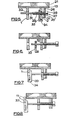
- FIG 6 shows the screw 27 released from the lock plate 33, allowing the platform 13 to be withdrawn from its mounting on the gussets 1, 2. If the platform 13 is fast in the mounting and needs to be released therefrom the lock plate 33 may be taken off the extension 31, reversed so that the lip 34 engages below the other gusset 1 and a plain portion of the lock plate blanks off the hole 32 in that gusset 1. The lock plate is held in this position (either manually or it can be provided with a spring clip to hold it in position on the gusset 1) and the screw 27 is advanced until the extension 31 engages the lock plate 33, as seen in Figure 7. Further rotation of the screw 27 now draws the platform 13 to the right (as drawn) out of its mounting. When the platform is free of the recess 11 in the gusset 1 remote from the lug 26 it can be withdrawn manually from the recess 12 in the rear gusset 2 without difficulty.
- the screw 27 When re-fitting the platform, or a replacement platform, the screw 27 is unscrewed to the position shown in Figure 6.
- the platform is entered into the recess 11, 12 and the lock plate 33 is returned to its original position and held abutting the inside of the near gusset 2 so as to receive the shank 29 when the screw 27 is rotated to advance it through the hole 32 in that gusset 2.
- the platform On tightening of the screw 27 the platform is secured in position, as shown in Figure 5.
- the platform 13 requires to be firmly fixed in its mounting so that, on. braking, no instability is induced due to relative movement between the platform and the gussets. This may be achieved by making the platform 13 a good fit in the recesses 11, 12 and relying on the screw 19 or 27, or clips 24, 25, for lateral location and retention of the platform.
- the gussets 1, 2 have recesses 38 with one inwardly inclined side 39 which provides a longitudinal location for a complementally inclined edge of the platform 13.
- the other side 41 of each of the recesses 38 is generally normal to the outer edge of the gusset and the opposite edge of the platform is similarly orientated whereby that end of the platform can be moved radially out of the recesses.
- Lateral locating of the platform may be provided by a slotted hook 42 secured, as by welding, to the underside of the platform 13 and which engages the adjacent gusset 2 when the platform is correctly positioned laterally.
- the gusset 2 may have a slotted lug 43 extending laterally from it, and a T-head bolt 44 suspended from the slot in the hook 42 may be inserted into the lug 43, and a nut 45 tightened on it to secure the platform 13 in the mounting.
- a locknut 46 can be provided on the bolt 44 and tightened to the outer surface of the lug 46 when securing the platform, as an additional security. On release of the nut 45 the locknut 46 may be screwed down against the lug 43, so forcing the bolt 44 outwards to engage the platform 13 and break any adhesion between the platform and the recesses, thereby releasing the platform to allow its withdrawal.
- adhesion may be broken by use of a lever between the lug 43 and hook 42 after release of wthe bolt 44.
- the lug 43 is shown positioned radially inwardly of the hook 42. However, the lug 43 may be offset from that position (conveniently a little to the left of the position as drawn) so that on tightening of the nut 4,5 a component of force longitudinally of the gussets is imparted to the platform to ensure that its inclined edge is fully engaged in the V-shaped end of the recess.
- the brake shoe has a single gusset it may be provided with laterally extending means, for example outrigger supports or guides, as part of the mounting for the platform whereby the platform is correctly located and supported on the gusset.
- the platform may be removably secured to the gusset, for example in a manner similar to what has been illustrated and described with reference to the accompanying drawings.
- the brake shoe Whilst the embodiments which have been illustrated and described with reference to Figures 1 to 8 and 10 have bridges 3, 4 between and connecting"the gussets the brake shoe may be of more conventional consdruction and utilise bridges which overlie the gussets and extend laterally beyond them in the manner of the platform of a conventional brake shoe, as 20A and 20B on the brake shoe 20 of Figure 9.
- the brake shoe 20 has a mounting for the platform 13 provided by a recess 20' between the bridges 20A, 20B.
- the recess as shown, has inclined sides 20C with which inclined edges 20D of the platform engage.
- Such bridges as 20A, 20B may provide guidance, location and retention for the platform, and indeed support for it.
- Such a construction is also applicable to a brake shoe in accordance with this invention having a single gusset.
- the platform 13 has joggled edges 47 and the recesses in gussets, 1, 2 have their opposite sides 48 shaped as slots to receive the edges 47.
- the recesses preferably have a raised portion 49 to provide support for the platform 13.
- the constructions of Figures 9 and 11 may be modified as illustrated and described with reference to Figure 10. Any of the various methods of lateral location, securing of the platform to the gusset or gussets and provision for release of the platform from its mounting which have already been described may be used with the brake shoes of Figures 9 and 11.
- the construction of Figure 9 may be modified by adapting the joggled construction of Figure 11.
- edges of the platform may be relieved where they are not engaged in the mounting so that if any corrosion product build-up should occur this will not inhibit withdrawal of the platform from the mounting.
- One end of a conventional trailer axle beam 55 has a brake anchor bracket 56 secured to it, as by welding.
- the anchor bracket 56 has a bore 57 to receive a bearing (not shown) for an S cam shaft 58.
- a bracket 59 provides a support for a further bearing (not shown) for the cam shaft 58.
- the cam shaft is rotated by an actuator (not shown) to expand the brake shoes 61, 62 against the inside wall of a brake drum 63 to brake a road wheel (not shown) fitted to a hub 64.
- the hub 64, the road wheel and brake drum 63 are secured together by wheel bolts 65, collars 66, 67 and nuts 68.
- the hub 64 is rotatably mounted on bearings (not shown) on the end of the axle beam 55.
- the anchor bracket 56 has two adjacent bores 69, 71 each of which receives a bush 72.
- the brake shoes 61, 62 have parallel spaced gussets with recesses for platforms generally as has been described.
- a platform 13 is shown on the one brake shoe 62 but has been omitted from the other brake shoe 61 for clarity.
- the gussets are shown with aligned holes 73, as in the brake shoe 20 of Figure 9.
- the gussets of the said one brake shoe 62 straddle the bore 69 so that the holes 73 are aligned with the bush 72 in the bore 69, and an anchor pin 74 is inserted in the bush and is retained therein by spring clips 75, 76 engaged in annular grooves at the end of the anchor pin, outboard of the gussets.
- the other brake shoe 61 is similarly pivotally anchored.
- a cam roller 77 and retainer 78 for the other end of each brake shoe are shown.
- the cam rollers are engaged by the cam on the end of the cam shaft 58.
- a brake release spring 79 is secured between the brake shoes by pins 81 which are located in aligned holes (as 7, Figures 1, 2) between the gussets of the respective brake shoes.
Landscapes
- Engineering & Computer Science (AREA)
- General Engineering & Computer Science (AREA)
- Mechanical Engineering (AREA)
- Braking Arrangements (AREA)
Abstract
Conventional shoe and drum brakes, for example for vehicles, require removal of the brake drum and the brake shoes for renewal of the friction linings.
A brake shoe is provided having gussets (1, 2) secured together in spaced parallel relationship by bridges (3, 4). A platform (13) carrying a friction lining (21) is separable from the gussets for servicing so that it can be withdrawn laterally without necessarily removing the brake drum.
The platform is received and retained in recesses (11,12) of the gussets which have inclined sides (11A, 12A) with which complementally inclined edges (14, 15) of the platform co-operate. A lug (16) depending from the platform (13) abuts against one gusset (2) to locate the platform laterally. A hole (17) in the lug (16) and a registering screw-threaded hole (18) in the gusset (2) are engaged by a screw (19) to secure the platform and gussets in assembled relationship. The lug (16) may be extended and have two screw-threaded holes to receive screws, as (19), which will react against the gusset (2) to withdraw the platform from the recesses for servicing.
Description
- This invention relates to brake assemblies of the internal expanding shoe and drum type wherein the brake shoes have at least one gusset or web, such as are used on heavy vehicles.
- Conventional shoe and drum type brakes require removal of the brake drum for access to the brake for replacement of worn friction linings. The wheel has to be removed to allow removal of the brake drum and the brake shoes have to be removed to be re-lined with linings of friction material or replaced by ready lined service brake shoes.
- This invention is directed to facilitating the replacement of friction linings of internal expanding shoe and drum type brake assemblies.
- According to one aspect of the present invention a brake shoe is provided comprising at least one generally arc-shaped gusset and a platform thereon having another face adapted to carry a friction lining, and being characterised in that the gusset and platform are separable components, a mounting is fast with the gusset, the platform has at least one surface which co-operates with the mounting to locate the platform relative to the gusset, and releasable means secure the platform and gusset together in assembled relationship.
- Means may be provided to act between the platform and gusset to cause release, or release and at least partial withdrawal, of the platform from the mounting.
- The mounting may include laterally extending means for guidance and/or location of the platform.
- The mounting preferably locates the platform longitudinally of the gusset.
- There may be more than one gusset. For example two generally arc-shaped gussets may be joined together in laterally spaced relationship whereon the mounting is provided.
- The platform may be generally arc-shaped.
- Where there are two gussets, for example, the releaseable means may secure the platform to one gusset or to both gussets.
- Co-operating means on the or each gusset and the platform may be provided whereby the platform is removably received and located on the convex face of the gusset or gussets.
- Means may be provided to locate the platform laterally relative to the gusset or gussets.
- Means may be provided to facilitate insertion of a platform into the mounting.
- According to a second aspect the invention also comprises a brake assembly including brake shoes in accordance with the first aspect of the invention set out herein.
- Embodiments of the invention will now be described by way of example with reference to the accompanying drawings in which:
- Figure 1 is a perspective view from above and one side showing the component parts of a brake shoe;
- Figure 2 is a similar view of an alternative brake shoe;
- Figure 3 is a scrap side view of part of the brake shoe of Figure 2, partly in section;
- Figure 4 is a perspective view of a release/withdrawal tool;
- Figures 5 to 8 are sections through a modified brake shoe with two parallel spaced gussets showing stages in the release and withdrawal of the platform from its mounting;
- Figure 9 is a perspective view of a brake shoe with laterally extending bridges.
- Figure 10 is a scrap view showing an alternative mounting and releaseable securing means for a platform;
- Figure 11 is a scrap view showing a further alternative mounting for a platform having joggled edges; and
- Figure 12 is a perspective view showing component parts of a brake assembly.
- Referring to Figure 1 of the drawings, the brake shoe shown has two generally arc-
shaped gussets holes 7 to provide an anchorage for a brake release spring. The other end of each gusset has aslot 8 to receive a brake anchor pin, such as is described in British Patent No. 1 580 963 of Rockwell International Corporation. Holes 9 provide an anchorage for a retaining spring. - The convex face of each
gusset recess - An arcuately
shaped platform 13, generally rectangular in plan view, hasbevelled edges recesses platform 13 has a downwardly dependinglug 16 which locates against onegusset 2 when the platform is assembled to the gussets, locating the platform transversely of the gussets. A hole 17 in thelug 16 registers with a screw-threadedhole 18 in thatgusset 2 and the assembly is secured with awing screw 19. Afriction lining 21 is secured to theplatform 13 on its convex face, as by bonding or riveting. The convex faces of therecesses platform 13. - Referring now to Figures 2 and 3, the brake shoe has gussets and a platform which are similar to those described with reference to Figure 1, the same reference numerals being used to identify corresponding parts of the brake shoe. The
platform 13 does not have alug 16. Alignedholes gussets spring clips platform 13 is provided with locating slots 13' which, when the platform is correctly assembled to the gussets, are aligned with the similar, cranked ends 24', 25' of thespring clips platform 13, as seen in Figure 3. - The brake shoe assembly of Figure 1 can be dis-assembled from one side by removal of the
wing screw 19 and withdrawal of theplatform 13 when thelining 21 is worn. A replacement linedplatform 13 can then be fitted in the manner described. There is thus no need to remove the gusset assembly, as has to be done with conventional brake shoes. If desired, thelug 16 may be extended (as shown in broken lines) and provided with a screw-threaded hole 16' at each side of the hole 17. In the event that theplatform 13 is fast in its mounting, screws can be inserted in these additional holes 16' and can be used to react against theadjacent gusset 2 to release theplatform 13 and assist in its removal from therecesses - With the brake shoe of Figures 2 and 3 the
spring clips platform 13 to be inserted and withdrawn from either side. The additional advantage of this feature will be realised when considering a trailer axle. It presents the possibility of replacement of the platform after removal of the brake dust cover, if fitted. This avoids the necessity of jacking the axle and removing the wheel or wheels and brake drum to gain access to the brake shoes. Similarly, the Figure 1 construction can be assembled to be accessed and serviced after removal of the dust cover, rather than after removal of the brake drum. - Provision may be made to release and assist withdrawal of the
platform 13 from the gusset assembly of Figure 2 by provision of holes in the concave face of the platform, aligned with, or outboard of, the slots 13' in which pegs on a withdrawal tool can be inserted. Such a tool, as 35, illustrated in Figure 4, might have two screw-threadedholes 36, into which screws are inserted to engage and react against theadjacent gusset recesses - If desired, provision may be made to facilitate insertion of the
platform 13, and its replacements, into therecesses holes 18 in the gussets, or in one of them, may be used in conjunction with correspondingly screw-threaded members and thelug 16 to cause theplatform 13 to be drawn into the recesses. Thewithdrawal tool 35 which has been described may also have plain holes, as 37, whereby, in conjunction with screw-threaded holes in theadjacent gusset - Referring now to Figures 5 to 8, the modified
platform 13 shown has alug 26 of generally U-section or L-section, for stiffness, with a screw-threaded hole 26' in which ascrew 27 is received. Thescrew 27 has ahead 28 of a conventional shape to be engaged by a spanner or drive socket, a threadedshank 29 and aplain extension 31 of reduced diameter. Thegussets holes 32 which are in alignment with the screw-threaded hole in thelug 26 and are of a size to allow theextension 31 andshank 29 respectively to pass through with clearance. A locking member comprising alock plate 33 has a screw-threaded hole to receive theshank 29 and alip 34 to locate under theadjacent gusset 2 so as to prevent rotation of the lock plate. - As seen in Figure 5, the
platform 13 is mounted on thegussets lug 26 against theadjacent gusset 2, and is retained by thescrew 27 thelock plate 33. A spring washer, not shown, may be located between thehead 28 and thelug 26 if desired so as to ensure location of the sides of thelug 26 against theadjacent gusset 2. - Figure 6 shows the
screw 27 released from thelock plate 33, allowing theplatform 13 to be withdrawn from its mounting on thegussets platform 13 is fast in the mounting and needs to be released therefrom thelock plate 33 may be taken off theextension 31, reversed so that thelip 34 engages below theother gusset 1 and a plain portion of the lock plate blanks off thehole 32 in thatgusset 1. The lock plate is held in this position (either manually or it can be provided with a spring clip to hold it in position on the gusset 1) and thescrew 27 is advanced until theextension 31 engages thelock plate 33, as seen in Figure 7. Further rotation of thescrew 27 now draws theplatform 13 to the right (as drawn) out of its mounting. When the platform is free of therecess 11 in thegusset 1 remote from thelug 26 it can be withdrawn manually from therecess 12 in therear gusset 2 without difficulty. - When re-fitting the platform, or a replacement platform, the
screw 27 is unscrewed to the position shown in Figure 6. The platform is entered into therecess lock plate 33 is returned to its original position and held abutting the inside of thenear gusset 2 so as to receive theshank 29 when thescrew 27 is rotated to advance it through thehole 32 in thatgusset 2. On tightening of thescrew 27 the platform is secured in position, as shown in Figure 5. - It will be appreciated that the
platform 13 requires to be firmly fixed in its mounting so that, on. braking, no instability is induced due to relative movement between the platform and the gussets. This may be achieved by making the platform 13 a good fit in therecesses screw - In an alternative construction, Figure 10, the
gussets recesses 38 with one inwardlyinclined side 39 which provides a longitudinal location for a complementally inclined edge of theplatform 13. Theother side 41 of each of therecesses 38 is generally normal to the outer edge of the gusset and the opposite edge of the platform is similarly orientated whereby that end of the platform can be moved radially out of the recesses. This construction makes it easier to release and withdraw the platform. Lateral locating of the platform may be provided by a slottedhook 42 secured, as by welding, to the underside of theplatform 13 and which engages theadjacent gusset 2 when the platform is correctly positioned laterally. Thegusset 2 may have a slottedlug 43 extending laterally from it, and a T-head bolt 44 suspended from the slot in thehook 42 may be inserted into thelug 43, and anut 45 tightened on it to secure theplatform 13 in the mounting. Alocknut 46 can be provided on thebolt 44 and tightened to the outer surface of thelug 46 when securing the platform, as an additional security. On release of thenut 45 thelocknut 46 may be screwed down against thelug 43, so forcing thebolt 44 outwards to engage theplatform 13 and break any adhesion between the platform and the recesses, thereby releasing the platform to allow its withdrawal. - Alternatively adhesion may be broken by use of a lever between the
lug 43 andhook 42 after release ofwthe bolt 44. Thelug 43 is shown positioned radially inwardly of thehook 42. However, thelug 43 may be offset from that position (conveniently a little to the left of the position as drawn) so that on tightening of the nut 4,5 a component of force longitudinally of the gussets is imparted to the platform to ensure that its inclined edge is fully engaged in the V-shaped end of the recess. - In the event that the brake shoe has a single gusset it may be provided with laterally extending means, for example outrigger supports or guides, as part of the mounting for the platform whereby the platform is correctly located and supported on the gusset. The platform may be removably secured to the gusset, for example in a manner similar to what has been illustrated and described with reference to the accompanying drawings.
- Whilst the embodiments which have been illustrated and described with reference to Figures 1 to 8 and 10 have bridges 3, 4 between and connecting"the gussets the brake shoe may be of more conventional consdruction and utilise bridges which overlie the gussets and extend laterally beyond them in the manner of the platform of a conventional brake shoe, as 20A and 20B on the brake shoe 20 of Figure 9. The brake shoe 20 has a mounting for the
platform 13 provided by a recess 20' between thebridges sides 20C with which inclined edges 20D of the platform engage. Such bridges as 20A, 20B may provide guidance, location and retention for the platform, and indeed support for it. Such a construction is also applicable to a brake shoe in accordance with this invention having a single gusset. - Referring now to Figure 11, the
platform 13 has jogglededges 47 and the recesses in gussets, 1, 2 have theiropposite sides 48 shaped as slots to receive theedges 47. The recesses preferably have a raised portion 49 to provide support for theplatform 13. The constructions of Figures 9 and 11 may be modified as illustrated and described with reference to Figure 10. Any of the various methods of lateral location, securing of the platform to the gusset or gussets and provision for release of the platform from its mounting which have already been described may be used with the brake shoes of Figures 9 and 11. The construction of Figure 9 may be modified by adapting the joggled construction of Figure 11. - It will be appreciated that suitable anti-corrosive protection may be applied to the edges of the platform. If desired, the edges of the platform may be relieved where they are not engaged in the mounting so that if any corrosion product build-up should occur this will not inhibit withdrawal of the platform from the mounting.
- Reference will now be made to the brake assembly shown in Figure 12. One end of a conventional
trailer axle beam 55 has abrake anchor bracket 56 secured to it, as by welding. Theanchor bracket 56 has abore 57 to receive a bearing (not shown) for anS cam shaft 58. Abracket 59 provides a support for a further bearing (not shown) for thecam shaft 58. The cam shaft is rotated by an actuator (not shown) to expand thebrake shoes brake drum 63 to brake a road wheel (not shown) fitted to ahub 64. Thehub 64, the road wheel andbrake drum 63 are secured together bywheel bolts 65,collars 66, 67 and nuts 68. Thehub 64 is rotatably mounted on bearings (not shown) on the end of theaxle beam 55. - The
anchor bracket 56 has two adjacent bores 69, 71 each of which receives abush 72. - The
brake shoes platform 13 is shown on the onebrake shoe 62 but has been omitted from theother brake shoe 61 for clarity. Instead of theslots 8 the gussets are shown with alignedholes 73, as in the brake shoe 20 of Figure 9. The gussets of the said onebrake shoe 62 straddle the bore 69 so that theholes 73 are aligned with thebush 72 in the bore 69, and ananchor pin 74 is inserted in the bush and is retained therein byspring clips 75, 76 engaged in annular grooves at the end of the anchor pin, outboard of the gussets. Theother brake shoe 61 is similarly pivotally anchored. Acam roller 77 andretainer 78 for the other end of each brake shoe are shown. The cam rollers are engaged by the cam on the end of thecam shaft 58. Abrake release spring 79 is secured between the brake shoes bypins 81 which are located in aligned holes (as 7, Figures 1, 2) between the gussets of the respective brake shoes.
Claims (14)
1. A brake shoe comprising at least one generally arc-shaped gusset and a platform thereon having an outer face adapted to carry a friction lining, characterised in that the gusset (1, 2) and platform (13) are separable components, a mounting (11, 12, 20', 38) is fast with the gusset (1, 2), the platform (13) has at least one surface (14, 15, 20D, 48) which co-operates with the mounting (11, 12, 20', 38) to locate the platform (13) relative to the gusset, and releasable means (16, 19, 24, 25, 27, 33, 35, 44, 45, 46) secure the platform and gusset together in assembled relationship.
2. A brake shoe according to Claim 1 characterised in that means (16, 19, 27, 33, 35, 44, 46) are provided to act between the platform (13) and the gusset (1, 2) to cause release, or release and at least partial withdrawal, of the platform (13) from the mounting (11, 12, 20', 38).
3. A brake shoe according to Claim 1 or Claim 2 characterised in that there are two gussets (1, 2) secured in spaced relationship by bridges (3, 4), and the mounting comprises a recess (11,12,38) defined by aligned relieved portions of the gussets (1, 2), a side (11A, 12A, 39, 48) of the recess (11, 12, 38) and an edge (14, 47) of the platform (13) having inter-engaging surfaces whereby the edge of the platform (14,47) is received and located by the sides (11A, 12A, 39, 48) of the recess (11, 12, 38).
4. A brake shoe according to Claim 1 or Claim 2 characterised in that there are two gussets (1, 2) secured in spaced relationship by transversely extending bridges (20A, 20B), and the mounting comprises a recess (20') between the bridges (20A, 20B), one side (20C) of the recess (20') and an edge (20D) of the platform (13) having interengaging surfaces whereby the edge (20D) of the platform (13) is received and located by the side (20C) of the recess (20').
5. A brake shoe as claimed in Claim 3 or Claim 4 characterised in that the engaging surfaces at the side (11A, 12A, 20C, 39) of the recess (11, 12, 20', 38) and the edge (14, 20D) of the platform are complementally inclined, the inclined edge (14, 20D) being engaged by the inclined side (11A, 12A, 20C, 39) and retained thereby.
6. A brake shoe as claimed in Claim 5 characterised in that two opposite sides (11A, 12A, 20C) of the recess (11, 12, 20') and two opposite edges (14, 15, 20D) of the platform (13) are complementally inclined whereby both of said edges of the platform are located and retained by both of said sides of the recess.
7. A brake shoe as claimed in Claim 3 or Claim 4 characterised in that the platform (13) has at least one joggled edge (47) and the recess (11, 12) has a side (48) shaped to receive and retain the joggled edge (47).
8. A brake shoe as claimed in any preceding claim characterised in that the platform (13) has a lug (16) extending generally parallel to the, or one, gusset (2), at an outer side of the gusset, there being a hole (17) through the lug (16), a registering screw-threaded. hole (18) in the gusset (2) and a screw-threaded member (19) received in the registering holes (17, 18) securing the platform (13) and gusset (2) in assembled relationship.
9. A brake shoe as claimed in any one of the Claims 1 to 7 characterised in that the platform (13) has a lug (26) extending generally parallel to the, or one, gusset (2), at an outer side of the gusset, a screw-threaded hole (26') in the lug (26) in register with a hole (32) in the gusset (2), a screw-threaded member (27) received in the registering holes (26', 32) and secured by a complementqlly screw-thrended locking member (33) at an inner side of the gnsset (2).
10. A brake shoe as claimed in Claim 9 characterised in that the locking member (33) is adapted to be used in conjunction with the screw-threadeda member (27) so as at least partially to withdraw platform (13) from the mounting (11, 12, 20A, 20B).
11. A brake shoe as claimed in any one of Claims 1 to 7 characterised in that the releasable means comprises spring or like clip members (24, 25) acting between the or each gusset (1, 2) and locations (13') provided on the platform (13).
12. A brake shoe as claimed in any one of Claims 1 to 4, Claim 5 or Claim 7 characterised in that the releasable means comprises co-operating screw-threaded members (44, 45) acting between abutments (42, 43) provided on the platform (13) and the, or one, gusset (2) respectively to secure the platform (13) and gusset in assembled relationship.
13. A brake shoe as claimed in Claim 8 characterised in that release means is provided operative to free the platform (13) for withdrawal from the mounting (11, 12) if it should become fast with the mounting, the release means comprising the lug (16), at least one screw-threaded hole (16') in the lug and engaged in the or each screw-threaded hole (16') a screw-threaded member which is able upon rotation to bear on the, or one, gusset (2) and urge the platform (13) to be moved relative to the mounting (11, 12).
14. A brake shoe as claimed in Claim 9 as dependent from Claim 3 or Claim 4 characterised in that release means is provided operative to free the platform (13) for withdrawal from the mounting (11, 12, 20', 38) if it should become fast with the mounting, the release means comprising the lug (26) extending generally parallel to the one gusset (2), the screw-threaded member (27) and the locking member (33), the screw-threaded member (27) and locking member (33) being adapted to be able to co-operate such that upon rotation of the screw-threaded member it reacts on the other gusset (1) through the locking membe (33) and causes the platform (13) to be moved relative to the mounting (11, 12, 20', 38).
Applications Claiming Priority (2)
| Application Number | Priority Date | Filing Date | Title |
|---|---|---|---|
| GB868615060A GB8615060D0 (en) | 1986-06-20 | 1986-06-20 | Brake assemblies |
| GB8615060 | 1986-06-20 |
Publications (1)
| Publication Number | Publication Date |
|---|---|
| EP0251545A1 true EP0251545A1 (en) | 1988-01-07 |
Family
ID=10599789
Family Applications (1)
| Application Number | Title | Priority Date | Filing Date |
|---|---|---|---|
| EP87305287A Withdrawn EP0251545A1 (en) | 1986-06-20 | 1987-06-15 | Brake assemblies |
Country Status (2)
| Country | Link |
|---|---|
| EP (1) | EP0251545A1 (en) |
| GB (2) | GB8615060D0 (en) |
Cited By (3)
| Publication number | Priority date | Publication date | Assignee | Title |
|---|---|---|---|---|
| EP0286254A2 (en) * | 1987-04-10 | 1988-10-12 | General Motors Corporation | Drum brake assembly, brake shoes for same, and methods |
| US20120137485A1 (en) * | 2009-06-17 | 2012-06-07 | Sonomev Freins (S.A.S.) | Shoe for a drum brake, and associated drum brake |
| EP3502508A1 (en) * | 2017-12-21 | 2019-06-26 | GFA Gothaer Fahrzeugachsen GmbH | Brake shoe of a vehicle drum brake |
Families Citing this family (3)
| Publication number | Priority date | Publication date | Assignee | Title |
|---|---|---|---|---|
| GB2255381B (en) * | 1991-05-01 | 1994-10-05 | Alfred Edward Vass | A brake shoe |
| US5469942A (en) * | 1994-08-26 | 1995-11-28 | Krumm, Sr.; Walter E. | Arcuate brake system with fastener-free replaceable brake lining |
| DE102011003721B4 (en) | 2011-02-07 | 2012-10-18 | Saf-Holland Gmbh | Brake shoe for drum brake |
Citations (10)
| Publication number | Priority date | Publication date | Assignee | Title |
|---|---|---|---|---|
| US1716393A (en) * | 1926-04-07 | 1929-06-11 | American Brake Materials Corp | Friction brake |
| US1724053A (en) * | 1926-05-01 | 1929-08-13 | American Brake Materials Corp | Friction brake |
| FR757380A (en) * | 1932-06-23 | 1933-12-26 | Lining for motor vehicle brakes and shoe therefor | |
| GB436897A (en) * | 1934-04-27 | 1935-10-21 | Claude Alexander Panton | Improvements relating to vehicle brake linings |
| US3398814A (en) * | 1967-01-09 | 1968-08-27 | Eaton Yale & Towne | Automotive vehicle brakes |
| GB1264116A (en) * | 1968-03-01 | 1972-02-16 | ||
| US3650360A (en) * | 1969-12-30 | 1972-03-21 | Robert L King | Truck brake |
| GB1337257A (en) * | 1969-12-24 | 1973-11-14 | Girling Ltd | Arcuate brake lining components for vehicle internal shoe drum brake assemblies |
| GB1345705A (en) * | 1970-05-14 | 1974-02-06 | Girling Ltd | Vehicle shoe drum brakes |
| GB1580963A (en) * | 1976-05-17 | 1980-12-10 | Rockwell International Corp | Brake shoe and brake assembly |
Family Cites Families (4)
| Publication number | Priority date | Publication date | Assignee | Title |
|---|---|---|---|---|
| GB397874A (en) * | 1932-02-26 | 1933-08-28 | Gerald Ayshford Pole Carew | Improvements in or relating to brakes |
| GB612433A (en) * | 1945-02-21 | 1948-11-12 | Paul Raymond Mceachran | Improvements in or relating to brake shoe construction |
| GB1264115A (en) * | 1968-03-01 | 1972-02-16 | ||
| AU545301B2 (en) * | 1980-10-22 | 1985-07-11 | Akebono Brake Industry Co., Ltd. | Pad type drum brake |
-
1986
- 1986-06-20 GB GB868615060A patent/GB8615060D0/en active Pending
-
1987
- 1987-06-02 GB GB08712926A patent/GB2191834A/en not_active Withdrawn
- 1987-06-15 EP EP87305287A patent/EP0251545A1/en not_active Withdrawn
Patent Citations (10)
| Publication number | Priority date | Publication date | Assignee | Title |
|---|---|---|---|---|
| US1716393A (en) * | 1926-04-07 | 1929-06-11 | American Brake Materials Corp | Friction brake |
| US1724053A (en) * | 1926-05-01 | 1929-08-13 | American Brake Materials Corp | Friction brake |
| FR757380A (en) * | 1932-06-23 | 1933-12-26 | Lining for motor vehicle brakes and shoe therefor | |
| GB436897A (en) * | 1934-04-27 | 1935-10-21 | Claude Alexander Panton | Improvements relating to vehicle brake linings |
| US3398814A (en) * | 1967-01-09 | 1968-08-27 | Eaton Yale & Towne | Automotive vehicle brakes |
| GB1264116A (en) * | 1968-03-01 | 1972-02-16 | ||
| GB1337257A (en) * | 1969-12-24 | 1973-11-14 | Girling Ltd | Arcuate brake lining components for vehicle internal shoe drum brake assemblies |
| US3650360A (en) * | 1969-12-30 | 1972-03-21 | Robert L King | Truck brake |
| GB1345705A (en) * | 1970-05-14 | 1974-02-06 | Girling Ltd | Vehicle shoe drum brakes |
| GB1580963A (en) * | 1976-05-17 | 1980-12-10 | Rockwell International Corp | Brake shoe and brake assembly |
Cited By (5)
| Publication number | Priority date | Publication date | Assignee | Title |
|---|---|---|---|---|
| EP0286254A2 (en) * | 1987-04-10 | 1988-10-12 | General Motors Corporation | Drum brake assembly, brake shoes for same, and methods |
| EP0286254A3 (en) * | 1987-04-10 | 1990-03-28 | General Motors Corporation | Drum brake assembly, brake shoes for same, and methods |
| US20120137485A1 (en) * | 2009-06-17 | 2012-06-07 | Sonomev Freins (S.A.S.) | Shoe for a drum brake, and associated drum brake |
| US10323709B2 (en) * | 2009-06-17 | 2019-06-18 | Gr Investissement (S.A.R.L.) | Shoe for a drum brake, and associated drum brake |
| EP3502508A1 (en) * | 2017-12-21 | 2019-06-26 | GFA Gothaer Fahrzeugachsen GmbH | Brake shoe of a vehicle drum brake |
Also Published As
| Publication number | Publication date |
|---|---|
| GB8712926D0 (en) | 1987-07-08 |
| GB2191834A (en) | 1987-12-23 |
| GB8615060D0 (en) | 1986-07-23 |
Similar Documents
| Publication | Publication Date | Title |
|---|---|---|
| AU594918B2 (en) | Locking fastener assembly for threaded joint | |
| US7404472B2 (en) | Disc brake caliper | |
| US6364426B1 (en) | Vehicle wheel hub and bearing unit assembly and method for producing same | |
| US4476968A (en) | Expanding shoe drum brake | |
| US20040200674A1 (en) | Quick-mount disc brake rotor | |
| EP0398092A1 (en) | Torque transmitting beam for wheel having brake torque drives | |
| EP0251545A1 (en) | Brake assemblies | |
| US5941349A (en) | Arcuate brake system with fastener-free, replaceable brake lining | |
| CA2063346C (en) | Visible brake block wear indicator | |
| US4552254A (en) | Drum brake spider assembly with cantilever anchor pin | |
| EP3763962A1 (en) | Rotor drive key assembly | |
| US8261890B2 (en) | Brake assembly with brake shoe and brake lining plate, and associated method | |
| WO1995005548A1 (en) | Brake shoe with removable brake shoe pads | |
| US4936426A (en) | Brake assembly | |
| US5343986A (en) | Disc brake repair means and method | |
| EP1408252A1 (en) | Multi-disc brake | |
| CN111465775B (en) | Improvement of brake shoe guiding device | |
| EP0078115B1 (en) | Expanding shoe drum brake | |
| EP3730357B1 (en) | Rotation restriction mechanism for maintenance | |
| US20020023808A1 (en) | Brake system with readily replaceable brake lining | |
| EP0044377B1 (en) | Brake assembly | |
| US4867285A (en) | Brake shoe mounting assembly | |
| US5975255A (en) | Quick-change brake shoe | |
| RU2144458C1 (en) | Method of and device for removing passenger car brake drum | |
| US6637553B1 (en) | Mounting stud retention system for use in a vehicle drum-in-hat disc brake assembly |
Legal Events
| Date | Code | Title | Description |
|---|---|---|---|
| PUAI | Public reference made under article 153(3) epc to a published international application that has entered the european phase |
Free format text: ORIGINAL CODE: 0009012 |
|
| AK | Designated contracting states |
Kind code of ref document: A1 Designated state(s): BE DE ES FR IT LU NL SE |
|
| STAA | Information on the status of an ep patent application or granted ep patent |
Free format text: STATUS: THE APPLICATION IS DEEMED TO BE WITHDRAWN |
|
| 18D | Application deemed to be withdrawn |
Effective date: 19880708 |
|
| RIN1 | Information on inventor provided before grant (corrected) |
Inventor name: DAWSON, GRAHAM STANLEY Inventor name: DIGGS, EDWARD JACKSON Inventor name: HORTON, DAVID |