EP1534963B1 - Vorrichtung einer bolzen- und muttersicherheitskupplung - Google Patents
Vorrichtung einer bolzen- und muttersicherheitskupplung Download PDFInfo
- Publication number
- EP1534963B1 EP1534963B1 EP03732683A EP03732683A EP1534963B1 EP 1534963 B1 EP1534963 B1 EP 1534963B1 EP 03732683 A EP03732683 A EP 03732683A EP 03732683 A EP03732683 A EP 03732683A EP 1534963 B1 EP1534963 B1 EP 1534963B1
- Authority
- EP
- European Patent Office
- Prior art keywords
- nut
- bolt
- shaft
- bolt assembly
- aperture
- Prior art date
- Legal status (The legal status is an assumption and is not a legal conclusion. Google has not performed a legal analysis and makes no representation as to the accuracy of the status listed.)
- Expired - Lifetime
Links
- 230000001419 dependent effect Effects 0.000 description 2
- 238000004026 adhesive bonding Methods 0.000 description 1
- 230000009286 beneficial effect Effects 0.000 description 1
- 238000004519 manufacturing process Methods 0.000 description 1
- 239000000463 material Substances 0.000 description 1
- 239000007769 metal material Substances 0.000 description 1
- 238000000034 method Methods 0.000 description 1
- 238000000926 separation method Methods 0.000 description 1
- 238000005476 soldering Methods 0.000 description 1
Images


Classifications
-
- F—MECHANICAL ENGINEERING; LIGHTING; HEATING; WEAPONS; BLASTING
- F16—ENGINEERING ELEMENTS AND UNITS; GENERAL MEASURES FOR PRODUCING AND MAINTAINING EFFECTIVE FUNCTIONING OF MACHINES OR INSTALLATIONS; THERMAL INSULATION IN GENERAL
- F16B—DEVICES FOR FASTENING OR SECURING CONSTRUCTIONAL ELEMENTS OR MACHINE PARTS TOGETHER, e.g. NAILS, BOLTS, CIRCLIPS, CLAMPS, CLIPS OR WEDGES; JOINTS OR JOINTING
- F16B39/00—Locking of screws, bolts or nuts
- F16B39/22—Locking of screws, bolts or nuts in which the locking takes place during screwing down or tightening
- F16B39/28—Locking of screws, bolts or nuts in which the locking takes place during screwing down or tightening by special members on, or shape of, the nut or bolt
-
- F—MECHANICAL ENGINEERING; LIGHTING; HEATING; WEAPONS; BLASTING
- F16—ENGINEERING ELEMENTS AND UNITS; GENERAL MEASURES FOR PRODUCING AND MAINTAINING EFFECTIVE FUNCTIONING OF MACHINES OR INSTALLATIONS; THERMAL INSULATION IN GENERAL
- F16B—DEVICES FOR FASTENING OR SECURING CONSTRUCTIONAL ELEMENTS OR MACHINE PARTS TOGETHER, e.g. NAILS, BOLTS, CIRCLIPS, CLAMPS, CLIPS OR WEDGES; JOINTS OR JOINTING
- F16B35/00—Screw-bolts; Stay-bolts; Screw-threaded studs; Screws; Set screws
- F16B35/04—Screw-bolts; Stay-bolts; Screw-threaded studs; Screws; Set screws with specially-shaped head or shaft in order to fix the bolt on or in an object
- F16B35/041—Specially-shaped shafts
- F16B35/044—Specially-shaped ends
- F16B35/045—Specially-shaped ends for retention or rotation by a tool
-
- F—MECHANICAL ENGINEERING; LIGHTING; HEATING; WEAPONS; BLASTING
- F16—ENGINEERING ELEMENTS AND UNITS; GENERAL MEASURES FOR PRODUCING AND MAINTAINING EFFECTIVE FUNCTIONING OF MACHINES OR INSTALLATIONS; THERMAL INSULATION IN GENERAL
- F16B—DEVICES FOR FASTENING OR SECURING CONSTRUCTIONAL ELEMENTS OR MACHINE PARTS TOGETHER, e.g. NAILS, BOLTS, CIRCLIPS, CLAMPS, CLIPS OR WEDGES; JOINTS OR JOINTING
- F16B41/00—Measures against loss of bolts, nuts, or pins; Measures against unauthorised operation of bolts, nuts or pins
- F16B41/005—Measures against unauthorised operation of bolts, nuts or pins
Definitions
- the present invention relates to safety nut and bolt and more specifically to a safety nut and bolt which can be easily joined together but cannot then be unscrewed in a typical fashion.
- Nuts and bolts are used in a multitude of different situations from use in the home to use in heavy industry. Particularly in heavy industry type uses, the principle utility of nuts and bolts is to secure items in position and prevent the separation of one or more objects. When a nut shape is loose, or is loosened from some reason, this can produce very dangerous situations as a bolt can simply fall out allowing the objects that it was supposed to be holding in position to move freely. It is particularly important in areas such as railways where the loosening of a bolt on a track can lead to disastrous consequences. This is particularly apparent when looking at the Potters Bar rail crash in which a loosened nut and bolt was implicated in the disaster. Also, in heavy industry such as wind turbines where there is a lot of vibration it has been known for nuts to become loose over time causing severe and sometimes dangerous problems.
- a further object of the present invention is to provide a safety nut and bolt system which has the strength to be used in heavy duty industry.
- roller bearings are part of a one way clutch bearing which can be inserted into the nut aperture.
- bearings may be part of a clutch bearing which can be attached to the end of a nut.
- the bolt is provided as a single piece.
- the bolt may be provided with a detachable tapered section at the end of the shaft.
- the detachable tapered section is provided with a threaded aperture through its longitudinal axis.
- the shaft has a threaded recess.
- the detachable tapered section is attached to the shaft using a securing screw which runs through the aperture in the tapered section and into the recess at the end of the shaft.
- the thread on the outside of the shaft may be right or left-handed.
- the thread in the aperture through the longitudinal axis of the shaft may be right or left-handed.
- the nut and bolt are made from a metallic material.
- the nut and bolt may be made from any appropriate material.
- a nut 6 and bolt 1 system comprising a bolt 1, which has an external thread 2 on the outer surface of the shaft.
- a detachable tapered section 4 is attached to the bolt 1 via a screw 5 which runs longitudinally through the detachable tapered section 4 and into a threaded recess 3 in the bolt 1.
- a nut 6 through which runs a partially threaded aperture.
- the aperture is provided with a recess 9 into which a one way clutch bearing 7 can fit.
- the one way clutch bearing 7 is held in the recess 9 by interference fit.
- the one way clutch bearing 7 contains roller bearings 8 which only allow movement in one direction around the circumference of the bearing 7.
- a one way clutch bearing allows shafts to move in only one direction.
- a one way clutch bearing is typically designed very much like a roller bearing but the rollers are allowed to move in one direction only. When the shaft turns in a direction that locks the clutch the rollers roll up small ramps and wedge into cavities preventing further movement.
- the nut 6 and bolt 1 can be joined together by screwing the bolt 1 through the nut 6 such that the tapered section 4 connects with the roller bearings 8.
- the roller bearings 8 will allow the bolt 1 to be screwed in one direction but will prevent the bolt 1 from then being unscrewed in the opposite direction.
- the only way that the bolt 1 can be removed from the nut 6 is by unscrewing the securing screw 5, releasing the tapered section 4 from the end of the bolt 1 such that the bolt section 1 can be released from the threaded section of the nut 6 whilst the tapered section 4 is still held in place by the roller bearings 8.
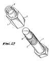
- the preferred embodiment in this case has a single piece of bolt as can be seen in Figure 2 (please note however although Figure 2 shows the single piece bolt it can be used with any of the variations of nut shown in Figures 1, 2 or 3).
- the bolt 1 is a single piece with the tapered section 4 not being detachable when the bolt one is screwed into the nut 6, the roller bearings 8 will hold it in place and it will not be possible to unscrew the bolt 1 once it is fitted.
- the only way in which the bolt 1 can be removed is by physically breaking of the head of the bolt 1.
- An alternative embodiment with either the single piece bolt 1 which is shown in Figure 2 or the multi-piece bolt 1 with a detachable tapered section 4 shown in Figures 1 and 3, is that instead of having a separate one way clutch bearing 7 either inserted into a recess of the nut as shown in Figure 1, or attached to the end of the nut as shown in Figure 2, there is simply roller bearings 8 provided on the inside surface of the nut 6 (as shown in Figure 3) .
Landscapes
- Engineering & Computer Science (AREA)
- General Engineering & Computer Science (AREA)
- Mechanical Engineering (AREA)
- Mechanical Operated Clutches (AREA)
- Mounting Of Bearings Or Others (AREA)
- Details Of Spanners, Wrenches, And Screw Drivers And Accessories (AREA)
- Braking Arrangements (AREA)
- Rolling Contact Bearings (AREA)
- Forging (AREA)
- Dowels (AREA)
Claims (10)
- Mutter- und Bolzenanordnung, umfassend eine Mutter (6) mit einer wenigstens teilweise mit Gewinde versehenen axial verlaufenden Öffnung und einen Bolzen (1), der einen Kopf und einen Schaft umfasst, dadurch gekennzeichnet, dass der Innenumfang der Mutter wenigstens ein zur Drehung in nur einer Richtung angeordnetes Rollenlager (8) umfasst und dass der Schaft des Bolzens mit einem Gewindeteil (2), der für den Eingriff mit dem Gewindeabschnitt der Mutter (6) ausgeführt ist, und einem relativ glatten Teil (4), der für den Eingriff mit dem wenigstens einen Rollenlager (8) ausgeführt ist, versehen ist.
- Mutter- und Bolzenanordnung nach Anspruch 1, bei der die Rollenlager (8) Teil eines Einwegkupplungslagers (7) sind.
- Mutter- und Bolzenanordnung nach Anspruch 2, bei der sich in der Mutternöffnung eine Aussparung befindet, in die das Kupplungslager (7) eingesetzt und durch Presspassung in ihr in Solllage gehalten werden kann.
- Mutter- und Bolzenanordnung nach Anspruch 1 und Anspruch 2, bei der die Rollenlager Teil eines Kupplungslagers sein können, das am Ende einer Mutter (6) angebracht werden kann.
- Mutter- und Bolzenanordnung nach einem der vorhergehenden Ansprüche, bei der der Bolzen(1) einstückig bereitgestellt ist.
- Mutter- und Bolzenanordnung nach den Ansprüchen 1 bis 4, bei der der Bolzen (1) mit einem abnehmbaren glatten Teil (4) am Ende des Schaftes versehen sein kann.
- Mutter- und Bolzenanordnung nach Anspruch 6, bei der der abnehmbare glatte Teil (4) mit einer mit Gewinde versehenen Öffnung durch seine Längsachse versehen ist.
- Mutter- und Bolzenanordnung nach Anspruch 6 und Anspruch 7, bei der der Schaft eine mit Gewinde versehene Aussparung (3) hat.
- Mutter- und Bolzenanordnung nach Anspruch 8, bei der der abnehmbare glatte Teil (4) mithilfe einer Sicherungsschraube (5), die durch die Öffnung im glatten Teil (4) und in die Aussparung (3) am Ende des Schaftes verläuft, am Schaft (2) angebracht ist.
- Mutter- und Bolzenanordnung nach einem der vorhergehenden Ansprüche, bei der das Gewinde an der Außenseite des Schaftes (2) und/oder das Gewinde in der Öffnung (3) durch die Längsachse des Schaftes links- oder rechtsgängig sein kann.
Applications Claiming Priority (9)
| Application Number | Priority Date | Filing Date | Title |
|---|---|---|---|
| GB0212949 | 2002-06-06 | ||
| GB0212949A GB0212949D0 (en) | 2002-06-06 | 2002-06-06 | Safety nut & bolt |
| GB0217100A GB0217100D0 (en) | 2002-06-06 | 2002-07-24 | Safety nut & bolt |
| GB0217100 | 2002-07-24 | ||
| GB0218819 | 2002-08-14 | ||
| GB0218819A GB0218819D0 (en) | 2002-08-14 | 2002-08-14 | Safety nutbolt |
| GB0221381A GB0221381D0 (en) | 2002-09-14 | 2002-09-14 | Safety nut and bolt |
| GB0221381 | 2002-09-14 | ||
| PCT/GB2003/002415 WO2003104661A2 (en) | 2002-06-06 | 2003-06-03 | Safety nut and bolt |
Publications (2)
| Publication Number | Publication Date |
|---|---|
| EP1534963A2 EP1534963A2 (de) | 2005-06-01 |
| EP1534963B1 true EP1534963B1 (de) | 2007-08-01 |
Family
ID=29740911
Family Applications (1)
| Application Number | Title | Priority Date | Filing Date |
|---|---|---|---|
| EP03732683A Expired - Lifetime EP1534963B1 (de) | 2002-06-06 | 2003-06-03 | Vorrichtung einer bolzen- und muttersicherheitskupplung |
Country Status (5)
| Country | Link |
|---|---|
| EP (1) | EP1534963B1 (de) |
| AT (1) | ATE368805T1 (de) |
| AU (1) | AU2003240069A1 (de) |
| DE (1) | DE60315309D1 (de) |
| WO (1) | WO2003104661A2 (de) |
Cited By (1)
| Publication number | Priority date | Publication date | Assignee | Title |
|---|---|---|---|---|
| WO2009024093A1 (fr) * | 2007-08-21 | 2009-02-26 | Beijing 3-D Spinal Orthopedics S & T Co. Ltd | Dispositif de fixation sous forme de boulon verrouillable et antirouille |
Families Citing this family (1)
| Publication number | Priority date | Publication date | Assignee | Title |
|---|---|---|---|---|
| CN112576605A (zh) * | 2020-12-28 | 2021-03-30 | 河南航天精工制造有限公司 | 一种螺母防松脱组件及防松脱螺栓螺母组件 |
Family Cites Families (3)
| Publication number | Priority date | Publication date | Assignee | Title |
|---|---|---|---|---|
| US2660212A (en) * | 1951-06-14 | 1953-11-24 | Gilbert S Allen | Roller wedge lock nut |
| CH666093A5 (de) * | 1985-05-30 | 1988-06-30 | Sulzer Ag | Schraubverbindung. |
| US4874275A (en) * | 1987-06-22 | 1989-10-17 | Gene W. Arant | Secure three-piece threaded fastener, and method |
-
2003
- 2003-06-03 AU AU2003240069A patent/AU2003240069A1/en not_active Abandoned
- 2003-06-03 EP EP03732683A patent/EP1534963B1/de not_active Expired - Lifetime
- 2003-06-03 AT AT03732683T patent/ATE368805T1/de not_active IP Right Cessation
- 2003-06-03 WO PCT/GB2003/002415 patent/WO2003104661A2/en not_active Ceased
- 2003-06-03 DE DE60315309T patent/DE60315309D1/de not_active Expired - Lifetime
Cited By (1)
| Publication number | Priority date | Publication date | Assignee | Title |
|---|---|---|---|---|
| WO2009024093A1 (fr) * | 2007-08-21 | 2009-02-26 | Beijing 3-D Spinal Orthopedics S & T Co. Ltd | Dispositif de fixation sous forme de boulon verrouillable et antirouille |
Also Published As
| Publication number | Publication date |
|---|---|
| WO2003104661A2 (en) | 2003-12-18 |
| WO2003104661A3 (en) | 2005-03-24 |
| AU2003240069A1 (en) | 2003-12-22 |
| EP1534963A2 (de) | 2005-06-01 |
| ATE368805T1 (de) | 2007-08-15 |
| DE60315309D1 (de) | 2007-09-13 |
| AU2003240069A8 (en) | 2003-12-22 |
Similar Documents
| Publication | Publication Date | Title |
|---|---|---|
| US6517301B2 (en) | Fastener assembly including a screw element and a supporting element | |
| US20110097174A1 (en) | Locking axle nut | |
| GB2491466A (en) | Security fastener | |
| KR930700782A (ko) | 록킹 패스너 | |
| US6896463B2 (en) | Spindle nut retainer | |
| CA2282712A1 (en) | Free running prevailing torque nut | |
| KR20160130663A (ko) | 볼트와 너트의 풀림방지구조 | |
| US4478458A (en) | Locking and anti-loosening construction for vehicle rim | |
| CN101105195A (zh) | 锁定式紧固螺栓 | |
| CN106979212A (zh) | 一种螺栓防松结构及其防松方法 | |
| DE69622200T2 (de) | Einzelmutter für leichtmetall-radanordnung eines kraftfahrzeuges | |
| WO2017020870A1 (zh) | 一种车轮 | |
| US3951076A (en) | Trolley construction | |
| EP1534963B1 (de) | Vorrichtung einer bolzen- und muttersicherheitskupplung | |
| CN101922496A (zh) | 一种螺栓及其螺栓连接结构 | |
| EP2754902A2 (de) | Schraubverbindungssystem | |
| CN201575036U (zh) | 组合式防拆卸圆螺母 | |
| WO2009024093A1 (fr) | Dispositif de fixation sous forme de boulon verrouillable et antirouille | |
| CN105402237A (zh) | 六角形组合式滚花滚柱防卸防盗螺母 | |
| CN203627497U (zh) | 一种轴端锁紧机构 | |
| EP1318316A3 (de) | Scheibe, Befestiger mit einer Scheibe sowie Verfahren und Kraftwerkzeug zu einer die Scheibe benutzenden Befestigung | |
| JPH11303840A (ja) | 悪事・脱落防止用のロック機構付きボルト及びナット | |
| CN111473035A (zh) | 一种止动槽螺母防松装置 | |
| KR20100012955A (ko) | 볼트와 너트의 풀림방지장치 | |
| JP2001050237A (ja) | ナット外し防止構造及びナット外し防止具並びにナット外し防止方法 |
Legal Events
| Date | Code | Title | Description |
|---|---|---|---|
| PUAI | Public reference made under article 153(3) epc to a published international application that has entered the european phase |
Free format text: ORIGINAL CODE: 0009012 |
|
| 17P | Request for examination filed |
Effective date: 20050105 |
|
| AK | Designated contracting states |
Kind code of ref document: A2 Designated state(s): AT BE BG CH CY CZ DE DK EE ES FI FR GB GR HU IE IT LI LU MC NL PT RO SE SI SK TR |
|
| AX | Request for extension of the european patent |
Extension state: AL LT LV MK |
|
| DAX | Request for extension of the european patent (deleted) | ||
| GRAP | Despatch of communication of intention to grant a patent |
Free format text: ORIGINAL CODE: EPIDOSNIGR1 |
|
| GRAS | Grant fee paid |
Free format text: ORIGINAL CODE: EPIDOSNIGR3 |
|
| GRAA | (expected) grant |
Free format text: ORIGINAL CODE: 0009210 |
|
| AK | Designated contracting states |
Kind code of ref document: B1 Designated state(s): AT BE BG CH CY CZ DE DK EE ES FI FR GB GR HU IE IT LI LU MC NL PT RO SE SI SK TR |
|
| REG | Reference to a national code |
Ref country code: GB Ref legal event code: FG4D |
|
| REG | Reference to a national code |
Ref country code: CH Ref legal event code: EP |
|
| REG | Reference to a national code |
Ref country code: IE Ref legal event code: FG4D |
|
| REF | Corresponds to: |
Ref document number: 60315309 Country of ref document: DE Date of ref document: 20070913 Kind code of ref document: P |
|
| PG25 | Lapsed in a contracting state [announced via postgrant information from national office to epo] |
Ref country code: ES Free format text: LAPSE BECAUSE OF FAILURE TO SUBMIT A TRANSLATION OF THE DESCRIPTION OR TO PAY THE FEE WITHIN THE PRESCRIBED TIME-LIMIT Effective date: 20071112 Ref country code: BG Free format text: LAPSE BECAUSE OF FAILURE TO SUBMIT A TRANSLATION OF THE DESCRIPTION OR TO PAY THE FEE WITHIN THE PRESCRIBED TIME-LIMIT Effective date: 20071101 Ref country code: FI Free format text: LAPSE BECAUSE OF FAILURE TO SUBMIT A TRANSLATION OF THE DESCRIPTION OR TO PAY THE FEE WITHIN THE PRESCRIBED TIME-LIMIT Effective date: 20070801 Ref country code: NL Free format text: LAPSE BECAUSE OF FAILURE TO SUBMIT A TRANSLATION OF THE DESCRIPTION OR TO PAY THE FEE WITHIN THE PRESCRIBED TIME-LIMIT Effective date: 20070801 |
|
| NLV1 | Nl: lapsed or annulled due to failure to fulfill the requirements of art. 29p and 29m of the patents act | ||
| REG | Reference to a national code |
Ref country code: CH Ref legal event code: PL |
|
| PG25 | Lapsed in a contracting state [announced via postgrant information from national office to epo] |
Ref country code: CH Free format text: LAPSE BECAUSE OF FAILURE TO SUBMIT A TRANSLATION OF THE DESCRIPTION OR TO PAY THE FEE WITHIN THE PRESCRIBED TIME-LIMIT Effective date: 20070801 Ref country code: LI Free format text: LAPSE BECAUSE OF FAILURE TO SUBMIT A TRANSLATION OF THE DESCRIPTION OR TO PAY THE FEE WITHIN THE PRESCRIBED TIME-LIMIT Effective date: 20070801 Ref country code: AT Free format text: LAPSE BECAUSE OF FAILURE TO SUBMIT A TRANSLATION OF THE DESCRIPTION OR TO PAY THE FEE WITHIN THE PRESCRIBED TIME-LIMIT Effective date: 20070801 |
|
| EN | Fr: translation not filed | ||
| PG25 | Lapsed in a contracting state [announced via postgrant information from national office to epo] |
Ref country code: BE Free format text: LAPSE BECAUSE OF FAILURE TO SUBMIT A TRANSLATION OF THE DESCRIPTION OR TO PAY THE FEE WITHIN THE PRESCRIBED TIME-LIMIT Effective date: 20070801 |
|
| PG25 | Lapsed in a contracting state [announced via postgrant information from national office to epo] |
Ref country code: DK Free format text: LAPSE BECAUSE OF FAILURE TO SUBMIT A TRANSLATION OF THE DESCRIPTION OR TO PAY THE FEE WITHIN THE PRESCRIBED TIME-LIMIT Effective date: 20070801 Ref country code: GR Free format text: LAPSE BECAUSE OF FAILURE TO SUBMIT A TRANSLATION OF THE DESCRIPTION OR TO PAY THE FEE WITHIN THE PRESCRIBED TIME-LIMIT Effective date: 20071102 |
|
| PG25 | Lapsed in a contracting state [announced via postgrant information from national office to epo] |
Ref country code: PT Free format text: LAPSE BECAUSE OF FAILURE TO SUBMIT A TRANSLATION OF THE DESCRIPTION OR TO PAY THE FEE WITHIN THE PRESCRIBED TIME-LIMIT Effective date: 20080102 Ref country code: SK Free format text: LAPSE BECAUSE OF FAILURE TO SUBMIT A TRANSLATION OF THE DESCRIPTION OR TO PAY THE FEE WITHIN THE PRESCRIBED TIME-LIMIT Effective date: 20070801 Ref country code: CZ Free format text: LAPSE BECAUSE OF FAILURE TO SUBMIT A TRANSLATION OF THE DESCRIPTION OR TO PAY THE FEE WITHIN THE PRESCRIBED TIME-LIMIT Effective date: 20070801 |
|
| PLBE | No opposition filed within time limit |
Free format text: ORIGINAL CODE: 0009261 |
|
| STAA | Information on the status of an ep patent application or granted ep patent |
Free format text: STATUS: NO OPPOSITION FILED WITHIN TIME LIMIT |
|
| PG25 | Lapsed in a contracting state [announced via postgrant information from national office to epo] |
Ref country code: SE Free format text: LAPSE BECAUSE OF FAILURE TO SUBMIT A TRANSLATION OF THE DESCRIPTION OR TO PAY THE FEE WITHIN THE PRESCRIBED TIME-LIMIT Effective date: 20071101 Ref country code: RO Free format text: LAPSE BECAUSE OF FAILURE TO SUBMIT A TRANSLATION OF THE DESCRIPTION OR TO PAY THE FEE WITHIN THE PRESCRIBED TIME-LIMIT Effective date: 20070801 |
|
| 26N | No opposition filed |
Effective date: 20080506 |
|
| PG25 | Lapsed in a contracting state [announced via postgrant information from national office to epo] |
Ref country code: FR Free format text: LAPSE BECAUSE OF FAILURE TO SUBMIT A TRANSLATION OF THE DESCRIPTION OR TO PAY THE FEE WITHIN THE PRESCRIBED TIME-LIMIT Effective date: 20080328 Ref country code: DE Free format text: LAPSE BECAUSE OF FAILURE TO SUBMIT A TRANSLATION OF THE DESCRIPTION OR TO PAY THE FEE WITHIN THE PRESCRIBED TIME-LIMIT Effective date: 20071103 |
|
| PG25 | Lapsed in a contracting state [announced via postgrant information from national office to epo] |
Ref country code: MC Free format text: LAPSE BECAUSE OF NON-PAYMENT OF DUE FEES Effective date: 20080630 |
|
| PG25 | Lapsed in a contracting state [announced via postgrant information from national office to epo] |
Ref country code: EE Free format text: LAPSE BECAUSE OF FAILURE TO SUBMIT A TRANSLATION OF THE DESCRIPTION OR TO PAY THE FEE WITHIN THE PRESCRIBED TIME-LIMIT Effective date: 20070801 Ref country code: IE Free format text: LAPSE BECAUSE OF NON-PAYMENT OF DUE FEES Effective date: 20080603 |
|
| PG25 | Lapsed in a contracting state [announced via postgrant information from national office to epo] |
Ref country code: SI Free format text: LAPSE BECAUSE OF FAILURE TO SUBMIT A TRANSLATION OF THE DESCRIPTION OR TO PAY THE FEE WITHIN THE PRESCRIBED TIME-LIMIT Effective date: 20070801 |
|
| PG25 | Lapsed in a contracting state [announced via postgrant information from national office to epo] |
Ref country code: CY Free format text: LAPSE BECAUSE OF FAILURE TO SUBMIT A TRANSLATION OF THE DESCRIPTION OR TO PAY THE FEE WITHIN THE PRESCRIBED TIME-LIMIT Effective date: 20070801 |
|
| PG25 | Lapsed in a contracting state [announced via postgrant information from national office to epo] |
Ref country code: LU Free format text: LAPSE BECAUSE OF NON-PAYMENT OF DUE FEES Effective date: 20080603 Ref country code: HU Free format text: LAPSE BECAUSE OF FAILURE TO SUBMIT A TRANSLATION OF THE DESCRIPTION OR TO PAY THE FEE WITHIN THE PRESCRIBED TIME-LIMIT Effective date: 20080202 |
|
| PG25 | Lapsed in a contracting state [announced via postgrant information from national office to epo] |
Ref country code: TR Free format text: LAPSE BECAUSE OF FAILURE TO SUBMIT A TRANSLATION OF THE DESCRIPTION OR TO PAY THE FEE WITHIN THE PRESCRIBED TIME-LIMIT Effective date: 20070801 |
|
| PG25 | Lapsed in a contracting state [announced via postgrant information from national office to epo] |
Ref country code: IT Free format text: LAPSE BECAUSE OF NON-PAYMENT OF DUE FEES Effective date: 20080630 |
|
| PGFP | Annual fee paid to national office [announced via postgrant information from national office to epo] |
Ref country code: GB Payment date: 20140602 Year of fee payment: 12 |
|
| GBPC | Gb: european patent ceased through non-payment of renewal fee |
Effective date: 20150603 |
|
| PG25 | Lapsed in a contracting state [announced via postgrant information from national office to epo] |
Ref country code: GB Free format text: LAPSE BECAUSE OF NON-PAYMENT OF DUE FEES Effective date: 20150603 |