EP0129931A1 - A rail vehicle brake system - Google Patents
A rail vehicle brake system Download PDFInfo
- Publication number
- EP0129931A1 EP0129931A1 EP84200869A EP84200869A EP0129931A1 EP 0129931 A1 EP0129931 A1 EP 0129931A1 EP 84200869 A EP84200869 A EP 84200869A EP 84200869 A EP84200869 A EP 84200869A EP 0129931 A1 EP0129931 A1 EP 0129931A1
- Authority
- EP
- European Patent Office
- Prior art keywords
- brake
- valve
- conduit
- piston
- pressure
- Prior art date
- Legal status (The legal status is an assumption and is not a legal conclusion. Google has not performed a legal analysis and makes no representation as to the accuracy of the status listed.)
- Granted
Links
Images


Classifications
-
- B—PERFORMING OPERATIONS; TRANSPORTING
- B60—VEHICLES IN GENERAL
- B60T—VEHICLE BRAKE CONTROL SYSTEMS OR PARTS THEREOF; BRAKE CONTROL SYSTEMS OR PARTS THEREOF, IN GENERAL; ARRANGEMENT OF BRAKING ELEMENTS ON VEHICLES IN GENERAL; PORTABLE DEVICES FOR PREVENTING UNWANTED MOVEMENT OF VEHICLES; VEHICLE MODIFICATIONS TO FACILITATE COOLING OF BRAKES
- B60T17/00—Component parts, details, or accessories of power brake systems not covered by groups B60T8/00, B60T13/00 or B60T15/00, or presenting other characteristic features
- B60T17/08—Brake cylinders other than ultimate actuators
- B60T17/085—Spring loaded brake actuators
-
- B—PERFORMING OPERATIONS; TRANSPORTING
- B60—VEHICLES IN GENERAL
- B60T—VEHICLE BRAKE CONTROL SYSTEMS OR PARTS THEREOF; BRAKE CONTROL SYSTEMS OR PARTS THEREOF, IN GENERAL; ARRANGEMENT OF BRAKING ELEMENTS ON VEHICLES IN GENERAL; PORTABLE DEVICES FOR PREVENTING UNWANTED MOVEMENT OF VEHICLES; VEHICLE MODIFICATIONS TO FACILITATE COOLING OF BRAKES
- B60T13/00—Transmitting braking action from initiating means to ultimate brake actuator with power assistance or drive; Brake systems incorporating such transmitting means, e.g. air-pressure brake systems
- B60T13/10—Transmitting braking action from initiating means to ultimate brake actuator with power assistance or drive; Brake systems incorporating such transmitting means, e.g. air-pressure brake systems with fluid assistance, drive, or release
- B60T13/24—Transmitting braking action from initiating means to ultimate brake actuator with power assistance or drive; Brake systems incorporating such transmitting means, e.g. air-pressure brake systems with fluid assistance, drive, or release the fluid being gaseous
- B60T13/26—Compressed-air systems
- B60T13/38—Brakes applied by springs or weights and released by compressed air
-
- B—PERFORMING OPERATIONS; TRANSPORTING
- B60—VEHICLES IN GENERAL
- B60T—VEHICLE BRAKE CONTROL SYSTEMS OR PARTS THEREOF; BRAKE CONTROL SYSTEMS OR PARTS THEREOF, IN GENERAL; ARRANGEMENT OF BRAKING ELEMENTS ON VEHICLES IN GENERAL; PORTABLE DEVICES FOR PREVENTING UNWANTED MOVEMENT OF VEHICLES; VEHICLE MODIFICATIONS TO FACILITATE COOLING OF BRAKES
- B60T15/00—Construction arrangement, or operation of valves incorporated in power brake systems and not covered by groups B60T11/00 or B60T13/00
- B60T15/02—Application and release valves
- B60T15/36—Other control devices or valves characterised by definite functions
Definitions
- This invention relates to a rail vehicle brake system, comprising an air brake cylinder with a piston, which is spring-biased for brake application on one side thereof, and a control system for selectively supplying pressurized air from a supply thereof to spaces in said cylinder on both sides of the piston.
- the braking force is obtained by supplying pressurized air to the brake cylinder at one side of the piston therein.
- the brake is released by discharging the air from the cylinder, the air thus being lost.
- the purpose of the invention is to provide a new and for many uses advantageous rail vehicle brake system, which reduces the losses of pressurized air at the brake operation and which provides a high-speed operation and can be of reduced size as compared with prior art brake systems particularly as far as the air brake cylinder is concerned.
- the high-speed operation is especially useful - together with the reduced air consumption - in systems with anti-skid function, where applications releases can occur with high frequency.
- the invention provides a rail vehicle brake system of the type referred to above, which is characterized in that a control system common for said two spaces - by selectively controlling the supply and discharge of pressurized air to and from, respectively, said brake cylinder spaces - is arranged to accomplish a continuously or stepwise controllable pressure differential between said spaces for service braking or for parking braking under the influence of the spring bias only.
- This brake system according to the invention will be referred to below as a differential brake.
- the differential brake unit shown therein includes an air brake cylinder comprising a cylinder housing 10 with a bolted-on lid 11, and a piston 12.
- An annular diaphragm 13 is attached to the piston 12 and is clamped between the cylinder housing 10 and the lid 11.
- the piston is connected to a piston rod 14, which in turn is connected to a conventional slack adjuster of pulling type, per se forming no part of the invention, the housing 15 of which is connected to the cylinder housing 10 and preferably is integral therewith.
- Two cup springs 16 are arranged between the cylinder housing 10 and the piston 12 on one side thereof, air conduits 17 and 18, respectively, being connected to the cylinder spaces on said one side of the piston and the opposite side of the piston.
- a bracket 19 projects from the cylinder housing 10 and preferably is integral therewith, and a brake lever 20 is pivoted to said bracket at one end thereof.
- the opposite end of the brake lever 20 is provided with a pivotal brake pad holder 21 having a replaceable brake pad 22.
- the slack adjuster is pivotally connected to the brake lever 20 at an intermediate point at 23.
- the cylinder housing 10 forms a second brake pad holder 24 having a replaceable brake pad 25.
- the brake unit thus described is suspended from an underframe or bogie of a rail vehicle in a manner well known in the art by means not shown in the drawing, with the brake pads 22 and 25 located one at each side of a disc, fragmentarily shown at 26 and connected to a wheel shaft to be braked.
- the springs 16 are effective to bias the piston 12 to the right as seen in the drawing forcing the brake lever 20 to swing in the counter -clockwise direction around the pivot thereof on the bracket 19, so that the brake pads 22 and 25 will be applied against the disc 26. Due to the existence of the slack adjuster the slack between the brake pads 22 and 25 and the disc 26 will always be held at the proper value irrespective of the wear of the brake pads 22 and 25. Accordingly a limited movement only of the piston 12 will be necessary for application of the brake.
- the differential brake unit accordingly is applied by the force of the springs 16.
- the braking force can be increased by supplying pressurized air through the conduit 17 to the cylinder space on the left side of the piston 12, and the brake will be released if the conduit 17 is vented to the atmosphere and pressurized air is supplied to the cylinder space on the right side of the piston 12 through the conduit 18 against the spring bias.
- the differential brake unit operates as a parking brake by the braking force applied by the springs 16, when no pressurized air is supplied through conduits 17 and 18.
- Fig. 2 having no reference numerals as the design and function of the unit shown therein is clear for any person skilled in the art, shows a pushing actuator of the same general type as the pulling unit according to Fig. 1. Also a tread brake unit or actuator of the spring brake type may be used in a differential system of the invention. In the examples presented below under reference to Figs. 3-5 the actuator is of the pulling type, whereas Figs. 6-8 show pushing actuators.
- the differential brake system disclosed therein is connected to a brake air conduit 27 extending through a rail vehicle.
- This conduit is for the supply of pressurized air to the brake system, and normally a predetermined pressure is maintained therein.
- the pressure of the pressurized air in the conduit 27 is decreased by the driver's brake control valve being operated.
- a relay valve 28 of a known type and forming no part of the present invention is connected to conduit 27, and under normal conditions (no braking) the relay valve connects conduit 27 to an air reservoir 29, which can comprise an auxiliary reservoir and an emergency reservoir as is known in the art.
- the relay valve also connects conduit 27 with a conduit 30 permanently connected to the reservoir 29 and extending to a differential valve 31.
- the differential valve 31 comprises a valve housing 32, which forms a central cavity 33 having a valve disc 34 biased by a helical pressure spring 35 against a seat 36 formed by the valve housing.
- a piston 37 forms a seat 38 and is held with this seat positioned substantially concentrically in the opening surrounded by the seat 36 by means of annular diaphragms 39 and 40, clamped to the valve housing 32 at the outer periphery thereof and to the piston 37 at the inner periphery thereof.
- the piston 37 is biased by a helical pressure spring 41 towards the valve disc 34, the spring being engaged between the piston and a cover 42 attached to the valve housing 32 and covering the piston 37 and the diaphragms 39 and 40.
- the cover has a central opening 43, through which the space defined between the valve housing 32 and the cover 42 is vented to the atmosphere.
- Diaphragms 39 and 40 defines an annular closed space 44 which communicates with a passage 45 in the valve housing 32, and a space 46 defined between the piston 37 and the valve housing 32 communicates with a passage 47 in the valve housing 32. Finally, there is provided in the valve housing 32 a third passage 48 communicating with the cavity 33. Conduit 30 is connected to this latter passage 48, while passages 45 and 47 are connected to conduits 17 and 18, respectively, mentioned above in connection with the description of the differential brake unit disclosed in Fig. 1.
- a conduit 49 extends between relay valve 28 and conduit 17. Normally, conduit 49 is vented to the atmosphere at relay valve 28, but when the pressure in conduit 27 is decreased, conduit 49 will be connected to reservoir 29, the communication between the reservoir and conduit 30 at one hand and conduit 27 at the other hand being interrupted.
- the brake unit Since the cylinder space on the side of the piston, where the cup springs 16 are arranged, is at zero pressure, conduit 49 being vented to the atmosphere through relay valve 28, the brake unit will be moved to the released position.
- the pressure of the pressurized air acts on the piston 37 in the space 46 against the bias of the spring 41, and at a predetermined pressure, which is lower than the maximum pressure of the pressurized air and preferably exerts on piston 12 a force which equals the force exerted on the piston by the cup springs 16, the piston 37 will have been displaced against the bias of the spring 41, such that the valve disc 34 rests again against the seat 36 and thus interrupts further supply of pressurized air to the brake cylinder.
- Pressurized air will be supplied at the pressure determined by the pressure decrease in conduit 27 from reservoir 29 to the space in the brake cylinder 11 where the cup springs 16 are arranged, while the cylinder space on the opposite side of piston 12 will be connected to the atmosphere. Accordingly, the brake will be applied under the bias of cup springs 16.
- the piston 37 is stabilized, i.e. the valve disc 34 is in engagement with the two seats 36 and 38, when the force exerted on the piston 37 by the pressures in space 44 (brake pressure) and in space 46 (differential pressure) equals the force of the spring 41.
- the braking force can be increased to a maximum value by continuously decreasing the pressure in conduit 27.
- the maximum service braking pressure can be adjusted in relation to the emergency braking pressure by arranging different relationships between the pressure area of the piston 37 in the space 46 and the pressure area of said piston in the space 44 and by adjusting the force of the spring 41.
- the share in the total brake force of the force from the cup springs 16 can be increased if the relationships are so chosen that at maximum braking force a reduced pressure is maintained on the side of the piston 12 which is opposite the cup springs 16.
- the differential valve 31 in the differential brake system disclosed therein is combined with an amplifier valve 50.
- This valve comprises a valve housing 51, which forms a cavity 52 with a valve disc 53 mounted therein and biased by a spring 54.
- the valve disc has a hollow valve rod 55 forming a through passage opening into the atmosphere.
- a diaphragm 56 is clamped in the housing at the periphery thereof and has a seat 57 at the side of the diaphragm facing the valve disc 53.
- a space 58 is defined in the valve housing 51 at said side of the diaphragm 56, and at the opposite side of the diaphragm a space 59 is defined between the valve housing 51 of the amplifier valve 50 and the valve housing 32 of the differential valve 31, said valve housings being attached to one another.
- the valve disc 53 is engaged with a seat 60, formed by the valve housing 51, under the bias of the spring 54, and also the seat 57 concentrical with the seat 60 is arranged to co-operate with the valve disc 53.
- Conduit 49 connected to passage 45 of the differential valve 31 is connected also to a passage 61 provided in the valve housing 32 and communicating with space 59 of the amplifier valve 50, and conduit 30 connected to passage 48 of the differential valve 31 is connected also to a passage 62 in the valve housing 51 of the amplifier valve 50, said passage 62 communicating with the cavity 52.
- the space 58 in valve housing 51 is connected by a passage 63 to conduit 17, communicating with the space in the air brake cylinder wherein the cup springs 16 are arranged, while the space on the opposite side of the piston 12 of the air brake cylinder communicates through conduit 18 with passage 47 in the valve housing 32 of the differential valve 31 as shown also in Fig. 3.
- the brake system of Fig. 4 comprises a motor 64 driving an air compressor 65, which supplies pressurized air to the reservoir 29 via a check valve 66 (but a traditional brake air supply system as in Fig. 3 may alternatively be used).
- a conduit 67 connects the reservoir 29 withrelay valve 28 which in Fig. 4 is shown to include a control valve 68 for continuous braking and a valve 69 for emergency braking.
- These valves are solenoid-type valves, whose solenoids are connected to an electronic control unit 70 of a type known in the art. This unit is operatively connected to a manually operated brake control and to automatic means for anti-skid, etc.
- valve 68 When the valve 68 is de-energized it is in the position shown in Fig. 4, connecting conduits 67 and 49 with each other. However, when the brake is released the valve 68 is energized so as to be adjusted to its other position, in which the connection between conduits 67 and 49 is interrupted and space 44 of differential valve 31 and space 59 of amplifier valve 50 are vented to the atmosphere. Reservoir 29 is connected through conduits 67 and 30 and passage 48 to the cavity 33 of the differential valve 31 and through conduits 67 and 30 and passage 62 to the cavity 52 of the amplifier valve 50.
- the differential valve 31 will be adjusted for the supply of pressurized air at maximum pressure through conduit 18 to the brake cylinder on the side of the piston 12 therein which is opposite to the cup springs 16 in the manner described with reference to Fig. 3.
- the pressurized air in the cavity 52 of the amplifier valve 50 will hold the valve disc 53 against the seat 60, so that the connection between the cavity 52 and the space 58 is interrupted.
- the brake cylinder on the side of the piston 12 on which the cup springs 16 are provided will be vented through conduit 17, passage 63, space 58 and the passage of the hollow rod 55 to the atmosphere, the diaphragm seat 57 being lifted from the valve disc 53.
- the brake unit will be adjusted to the released position as described previously with reference to Fig. 3.
- conduit 67 will be connected to conduit 49.
- the pressure of the pressurized air in the conduit 49 and the space 44 of the differential valve adjusted as described with reference to Fig. 3 will not act directly in the brake cylinder 10 on the side of the piston 12 where the cup springs 16 are arranged.
- This pressure will instead be transferred through passage 61 to the space 59 of the amplifier valve 50, where it will act on the movable seat 57, which will be pressed against the valve disc 53. Accordingly, the valve disc will be lifted from the seat.
- the pressure supplied to said space in the brake cylinder will be stabilized at a value determined by the pressure established in conduit 49 by the adjustment of the valve 69, the valve disc 53 being engaged with the seat 60 under the force applied by the spring 54 and the air pressure in the cavity 58 against the force exerted on the valve disc by the pressurized air in the space 59 over the movable seat 57.
- the pressure in the brake cylinder 10 is proportionally reduced through conduit 18 via the differential valve in the same manner as described previously with reference to Fig. 3.
- Fig. 4 provides the advantage that the valve 58 can be of a simple construction and can have small dimensions due to the fact that the supply of pressurized air to the brake cylinder is accomplished by means of the amplifier valve 50.
- Emergency braking is effected by de-energizing the valve 69 so as to provide a direct connection between the reservoir 29 and the conduit 49 in order to raise to the maximum value the pressure in the brake cylinder on the side of the piston 12 where the cup springs 16 are provided.
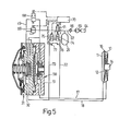
- Fig. 5 shows the same brake system as that shown in Fig. 4 but with an arrangement for reducing the air consumption in the brake system and thus reducing the energy consumption in the system.
- a solenoid valve 71 operatively connected to the electronic control unit 70. When de-energized this valve is open; it will be closed when energized.
- Conduits 72 and 73 are connected to conduits 17 and 18, respectively. Also these valves are operatively connected to the electronic control unit 70, and they are in the closed position when de-energized. They will be adjusted to the open position when energized under the control of the control unit 70.
- solenoid valves 71, 74, and 75 are in the de-energized position as shown in Fig. 5.
- solenoid valves 71 and 75 will be energized so as to interrupt the supply of pressurized air from the reservoir 29 and to connect the brake cylinder on the side of the piston 12 which is opposite to the cup springs 16 via valve 75 with conduit 67, so that the pressurized air expelled from the cylinder on said side of the piston 12 will be supplied to the brake cylinder on the side of the piston 12, where the cup springs 16 are arranged, under the control of the differential valve 31 and the amplifier valve 50 in the manner described with reference to Fig. 4.
- Sensors 76 and 77 sensing the pressure in the brake cylinder on opposite sides of the piston 12 supply signals to the electronic control unit 70, which are proportional to said pressures, and at a predetermined lower value of the difference between the pressures indicated by the sensors, the electronic unit de-energizes valves 71 and 75 for the supply of pressurized air to the brake cylinder from the reservoir 29 during the final phase of the operation for applying the brake in the manner described with reference to Fig. 4.
- solenoid valves 71 and 74 When the brake is to be released solenoid valves 71 and 74 will be energized under the control of the electronic control unit 70, so that pressurized air will be transferred from the space of the brake cylinder where the cup springs 16 are arranged to the opposite side of the piston 12 via the solenoid valve 74 in a manner analogous to that described with reference to the application of the brake, and also in this case valves 71 and 74 will be de-energized at a predetermined lower pressure difference between the pressures indicated by the sensors 76 and 77 for the supply of pressurized air from the reservoir 29 during the final phase of the operation for releasing the brake.
- the brake system of Fig. 6, to which reference now is made, is of the step control type contrary to the systems of the continuous control type previously decribed herein.
- a conduit 78 for pressurized air three brake systems are connected, associated e.g. one to each bogie of a rail vehicle.
- Each brake system comprises a reservoir 29 connected to conduit 78 via a check valve 66.
- the reservoir is connected through a conduit 67 to two brake units of the same general type as previously described herein and generally indicated at 79 over a brake control valve 80.
- This valve is operatively connected to an electronic control unit 70, which can be of a type well-known in the art and to which control signals are supplied, such as a brake command signal, an emergency brake signal, a skid indication signal, a load weight signal, etc.
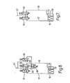
- the brake control valve 80 is arranged as shown in Fig. 7 and comprises two solenoid valves 81 and 82. Both valves are shown in a de-energized condition in Fig. 7.
- valve 81 connects conduit 67 through conduit 17 with the brake cylinder 79 at the side of the piston 12 therein on which the cup springs 16 are arranged, while the other valve 82 vents the cylinder space on the opposite side of the piston 12 to the atmosphere through conduit 18.
- valve 81 vents the associated brake cylinder space to the atmosphere
- valve 82 connects the associated brake cylinder space with conduit 67.
- both valves 81 and 82 are energized, and accordingly the cylinder space wherein the cup springs 16 are arranged is vented to the atmosphere, and the cylinder space on the opposite side of the piston 12 is under the maximum pressure maintained in the reservoir 29.
- the brake can be partly applied by de-energizing valve 81, so that the brake cylinder spaces on opposite sides of the piston 12 both will be connected to the maximum air pressure.
- the brake is fully applied by de-energizing both valves 81 and 82 - the condition shown in Fig. 7 - wherein the brake cylinder space associated with valve 81 is still under maximum pressure, while the opposite cylinder space is vented to the atmosphere.
- valves 81 and 82 have no connection for venting conduits 17 and 18 to the atmosphere, a third solenoid valve 83 being provided for this purpose.
- valve 81 In the de-energized position shown in Fig. 8 valve 81 connects conduit 67 to conduit 17, and in the energized position this valve connects conduit 17 to a conduit 84.
- This conduit is connected via a check valve 85 and a pressure reduction valve 86 to the valve 83, which in the de-energized position shown vents conduit 84 via the check valve 85 to the atmosphere.
- valve 82 vents conduit 18 via conduit 84 and check valve 85 to the atmosphere via valve 83, and when valve 82 is energized conduit 18 is connected to conduit 67.
- Valve 83 when energized connects conduit 84 via the pressure reduction valve 86 to conduit 67 and then, depending on the operational condition of valve 81 and 82, respectively, conduit 17 and 18, respectively, will be connected to conduit 67 via pressure reduction valve 86 and valve 83. In this case it is assumed that the pressure reduction valve 86 reduces the pressure maintained in conduit 67 by 50%.
- valves 81 and 82 are energized while valve 83 is de-energized, and accordingly the maximum pressure maintained in reservoir 29 is supplied through conduit 18 to the space in the brake cylinder 79 which is opposite to the cup springs 16, while the space containing the cup springs is vented to the atmosphere via check valve 85 and valve 83.
- valves 81, 82, and 83 are all energized, which means that maximum pressure is supplied through conduit 18, while half the maximum pressure is supplied through conduit 17 via the reduction valve 86. This step corresponds to 1/4 of the maximum braking effect.
- a second step valve 82 only is energized, and maximum pressure is supplied through both conduits 17 and 18, which corresponds to 1/2 of the maximum braking effect.
- valve 83 In a third step valve 83 only is energized, and accordingly the maximum pressure is supplied through conduit 17, while the pressure which is reduced by 50% is supplied through conduit 18. This condition corresponds to 3/4 of the maximum braking effect.
Abstract
Description
- This invention relates to a rail vehicle brake system, comprising an air brake cylinder with a piston, which is spring-biased for brake application on one side thereof, and a control system for selectively supplying pressurized air from a supply thereof to spaces in said cylinder on both sides of the piston.
- In a conventional air brake system the braking force is obtained by supplying pressurized air to the brake cylinder at one side of the piston therein. The brake is released by discharging the air from the cylinder, the air thus being lost.
- In a known modification of this brake the braking force is obtained by means of a very heavy pretensioned spring, which acts on one side of the piston, the brake being released by the supply of pressurized air on the opposite side of the piston. When the brake is to be applied again, also in this case air has to be discharged and will be lost.
- The purpose of the invention is to provide a new and for many uses advantageous rail vehicle brake system, which reduces the losses of pressurized air at the brake operation and which provides a high-speed operation and can be of reduced size as compared with prior art brake systems particularly as far as the air brake cylinder is concerned. The high-speed operation is especially useful - together with the reduced air consumption - in systems with anti-skid function, where applications releases can occur with high frequency.
- For said purpose the invention provides a rail vehicle brake system of the type referred to above, which is characterized in that a control system common for said two spaces - by selectively controlling the supply and discharge of pressurized air to and from, respectively, said brake cylinder spaces - is arranged to accomplish a continuously or stepwise controllable pressure differential between said spaces for service braking or for parking braking under the influence of the spring bias only.
- This brake system according to the invention will be referred to below as a differential brake.
- The invention will be described in more detail below with reference to the accompanying drawings in which
- Fig. 1 is a side view, partly in axial cross-section, of one embodiment of a differential brake unit for use in a system according to the invention,
- Fig. 2 is a partly sectional view of a modification of the brake unit in Fig. 1,
- Fig. 3 is a diagrammatic view of a differential brake system of the invention including a differential valve shown in axial cross-sectional view,
- Fig. 4 is a diagrammatic view of a differential brake system, similar to that in Fig. 3, wherein the differential valve is combined with an amplifier valve,
- Fig. 5 is a diagrammatic view similar to Fig. 4 and showing a modification of the brake system shown in Fig. 4,
- Fig. 6 is a diagrammatic view of a further embodiment of the brake system, and
- Figs. 7 and 8 are diagrammatic detail views of two embodiments of the brake control valve arrangement in the system of Fig. 6. Description of Preferred Embodiments
- Referring to Fig. 1, the differential brake unit shown therein includes an air brake cylinder comprising a
cylinder housing 10 with a bolted-onlid 11, and apiston 12. Anannular diaphragm 13 is attached to thepiston 12 and is clamped between thecylinder housing 10 and thelid 11. The piston is connected to apiston rod 14, which in turn is connected to a conventional slack adjuster of pulling type, per se forming no part of the invention, thehousing 15 of which is connected to thecylinder housing 10 and preferably is integral therewith. Twocup springs 16 are arranged between thecylinder housing 10 and thepiston 12 on one side thereof,air conduits - A
bracket 19 projects from thecylinder housing 10 and preferably is integral therewith, and abrake lever 20 is pivoted to said bracket at one end thereof. The opposite end of thebrake lever 20 is provided with a pivotalbrake pad holder 21 having areplaceable brake pad 22. The slack adjuster is pivotally connected to thebrake lever 20 at an intermediate point at 23. Thecylinder housing 10 forms a secondbrake pad holder 24 having areplaceable brake pad 25. - The brake unit thus described is suspended from an underframe or bogie of a rail vehicle in a manner well known in the art by means not shown in the drawing, with the
brake pads - The
springs 16 are effective to bias thepiston 12 to the right as seen in the drawing forcing the brake lever 20 to swing in the counter -clockwise direction around the pivot thereof on thebracket 19, so that thebrake pads disc 26. Due to the existence of the slack adjuster the slack between thebrake pads disc 26 will always be held at the proper value irrespective of the wear of thebrake pads piston 12 will be necessary for application of the brake. - Provided that no air pressure is maintained in the cylinder space on the right side of the
piston 12,conduit 18 being connected to the atmosphere, the differential brake unit accordingly is applied by the force of thesprings 16. The braking force can be increased by supplying pressurized air through theconduit 17 to the cylinder space on the left side of thepiston 12, and the brake will be released if theconduit 17 is vented to the atmosphere and pressurized air is supplied to the cylinder space on the right side of thepiston 12 through theconduit 18 against the spring bias. - As will be seen, the differential brake unit operates as a parking brake by the braking force applied by the
springs 16, when no pressurized air is supplied throughconduits - Fig. 2, having no reference numerals as the design and function of the unit shown therein is clear for any person skilled in the art, shows a pushing actuator of the same general type as the pulling unit according to Fig. 1. Also a tread brake unit or actuator of the spring brake type may be used in a differential system of the invention. In the examples presented below under reference to Figs. 3-5 the actuator is of the pulling type, whereas Figs. 6-8 show pushing actuators.
- Referring now to Fig. 3, the differential brake system disclosed therein is connected to a
brake air conduit 27 extending through a rail vehicle. This conduit is for the supply of pressurized air to the brake system, and normally a predetermined pressure is maintained therein. When braking is to be initiated the pressure of the pressurized air in theconduit 27 is decreased by the driver's brake control valve being operated. - A
relay valve 28 of a known type and forming no part of the present invention is connected toconduit 27, and under normal conditions (no braking) the relay valve connectsconduit 27 to anair reservoir 29, which can comprise an auxiliary reservoir and an emergency reservoir as is known in the art. The relay valve also connectsconduit 27 with aconduit 30 permanently connected to thereservoir 29 and extending to adifferential valve 31. - The
differential valve 31 comprises avalve housing 32, which forms a central cavity 33 having avalve disc 34 biased by ahelical pressure spring 35 against a seat 36 formed by the valve housing. Apiston 37 forms aseat 38 and is held with this seat positioned substantially concentrically in the opening surrounded by the seat 36 by means ofannular diaphragms valve housing 32 at the outer periphery thereof and to thepiston 37 at the inner periphery thereof. Thepiston 37 is biased by ahelical pressure spring 41 towards thevalve disc 34, the spring being engaged between the piston and acover 42 attached to thevalve housing 32 and covering thepiston 37 and thediaphragms central opening 43, through which the space defined between thevalve housing 32 and thecover 42 is vented to the atmosphere. -
Diaphragms space 44 which communicates with apassage 45 in thevalve housing 32, and aspace 46 defined between thepiston 37 and thevalve housing 32 communicates with apassage 47 in thevalve housing 32. Finally, there is provided in the valve housing 32 athird passage 48 communicating with the cavity 33.Conduit 30 is connected to thislatter passage 48, whilepassages conduits - A
conduit 49 extends betweenrelay valve 28 andconduit 17. Normally,conduit 49 is vented to the atmosphere atrelay valve 28, but when the pressure inconduit 27 is decreased,conduit 49 will be connected toreservoir 29, the communication between the reservoir andconduit 30 at one hand andconduit 27 at the other hand being interrupted. - When the pressure of the air in
conduit 27 is at maximum, the brake is released. In this operational condition of the differential brake system, thereservoir 29 is connected toconduit 27, and this conduit and the reservoir are connected throughconduit 30 andpassage 48 to the cavity 33. Thevalve disc 34 in this cavity is engaged by thepiston 37 and is held in a position in which it is lifted from the seat 36 under the bias of thespring 41, which is stronger than thespring 35. Thus, pressurized air at maximum pressure will be supplied from cavity 33 topassage 47 and then throughconduit 18 to thebrake cylinder 11 on the side of thepiston 12 therein which is opposite to thecup springs 16. Since the cylinder space on the side of the piston, where thecup springs 16 are arranged, is at zero pressure,conduit 49 being vented to the atmosphere throughrelay valve 28, the brake unit will be moved to the released position. The pressure of the pressurized air acts on thepiston 37 in thespace 46 against the bias of thespring 41, and at a predetermined pressure, which is lower than the maximum pressure of the pressurized air and preferably exerts on piston 12 a force which equals the force exerted on the piston by thecup springs 16, thepiston 37 will have been displaced against the bias of thespring 41, such that thevalve disc 34 rests again against the seat 36 and thus interrupts further supply of pressurized air to the brake cylinder. - It is now assumed that the brake is to be applied by service pressure. Then, the pressure of the pressurized air in
conduit 27 is decreased to a predetermined value, at which therelay valve 28 will be adjusted to the position in whichreservoir 29 andconduit 30 are disconnected fromconduit 27 andconduit 49 is connected toreservoir 29 in parallel withconduit 30. However, the pressure inconduit 49 will not be at the same value as the pressure inreservoir 29, which equals the maximum pressure maintained inconduit 27.Relay valve 28 is of the type well known in the art, which supplies to conduit 49 a pressure which is inversely proportional to the decrease of the pressure inconduit 27. Thus (and somewhat simplified), if the brake regulating part of the pressure inconduit 27 is decreased by for example 20%, the pressure inconduit 49 will be increased from zero to a pressure which equals 20% of the pressure in thereservoir 29. This means that the pressurized air now acts on thepiston 37 not only in thespace 46 but also in thespace 44 defined between thediaphragms space 44 throughpassage 45. Under the pressure acting thereon thepiston 37 will be lifted fromvalve disc 34, engaging seat 36, against the bias ofspring 41 such thatspace 46 and accordinglypassage 47 andconduit 18 will be vented to the atmosphere throughopening 43. Pressurized air will be supplied at the pressure determined by the pressure decrease inconduit 27 fromreservoir 29 to the space in thebrake cylinder 11 where the cup springs 16 are arranged, while the cylinder space on the opposite side ofpiston 12 will be connected to the atmosphere. Accordingly, the brake will be applied under the bias of cup springs 16. - When the
piston 12 is displaced to the left as seen in Fig. 3 under the bias of cup springs 16, the cylinder space on the side of the piston which is opposite to the cup springs will be vented to the atmosphere throughconduit 18,passage 47,space 46, andopening 43, until the force on thepiston 37 exerted by the pressure inspaces spring 41, at which time the connection for venting the cylinder space on the side of thepiston 12, which is opposite to the cup springs 16, throughconduit 18 will be interrupted due to the fact that thepiston 37 will engage thevalve disc 34, which is firmly held against the seat 36 under the pressure of the pressurized air in thereservoir 29. The braking force will be determined by the pressure decrease inconduit 27, and (again somewhat simplified) if this decrease is 20% as was assumed above, 20% of the maximum braking force will be applied. - The
piston 37 is stabilized, i.e. thevalve disc 34 is in engagement with the twoseats 36 and 38, when the force exerted on thepiston 37 by the pressures in space 44 (brake pressure) and in space 46 (differential pressure) equals the force of thespring 41. - The braking force can be increased to a maximum value by continuously decreasing the pressure in
conduit 27. The maximum service braking pressure can be adjusted in relation to the emergency braking pressure by arranging different relationships between the pressure area of thepiston 37 in thespace 46 and the pressure area of said piston in thespace 44 and by adjusting the force of thespring 41. - Correspondingly, the share in the total brake force of the force from the cup springs 16 can be increased if the relationships are so chosen that at maximum braking force a reduced pressure is maintained on the side of the
piston 12 which is opposite the cup springs 16. - Referring now to Fig. 4, the
differential valve 31 in the differential brake system disclosed therein is combined with anamplifier valve 50. This valve comprises avalve housing 51, which forms a cavity 52 with avalve disc 53 mounted therein and biased by aspring 54. The valve disc has a hollow valve rod 55 forming a through passage opening into the atmosphere. Adiaphragm 56 is clamped in the housing at the periphery thereof and has a seat 57 at the side of the diaphragm facing thevalve disc 53. A space 58 is defined in thevalve housing 51 at said side of thediaphragm 56, and at the opposite side of the diaphragm aspace 59 is defined between thevalve housing 51 of theamplifier valve 50 and thevalve housing 32 of thedifferential valve 31, said valve housings being attached to one another. Thevalve disc 53 is engaged with a seat 60, formed by thevalve housing 51, under the bias of thespring 54, and also the seat 57 concentrical with the seat 60 is arranged to co-operate with thevalve disc 53. -
Conduit 49 connected topassage 45 of thedifferential valve 31 is connected also to a passage 61 provided in thevalve housing 32 and communicating withspace 59 of theamplifier valve 50, andconduit 30 connected topassage 48 of thedifferential valve 31 is connected also to apassage 62 in thevalve housing 51 of theamplifier valve 50, saidpassage 62 communicating with the cavity 52. The space 58 invalve housing 51 is connected by apassage 63 toconduit 17, communicating with the space in the air brake cylinder wherein the cup springs 16 are arranged, while the space on the opposite side of thepiston 12 of the air brake cylinder communicates throughconduit 18 withpassage 47 in thevalve housing 32 of thedifferential valve 31 as shown also in Fig. 3. - The brake system of Fig. 4 comprises a
motor 64 driving anair compressor 65, which supplies pressurized air to thereservoir 29 via a check valve 66 (but a traditional brake air supply system as in Fig. 3 may alternatively be used). Aconduit 67 connects thereservoir 29withrelay valve 28 which in Fig. 4 is shown to include acontrol valve 68 for continuous braking and avalve 69 for emergency braking. These valves are solenoid-type valves, whose solenoids are connected to anelectronic control unit 70 of a type known in the art. This unit is operatively connected to a manually operated brake control and to automatic means for anti-skid, etc. - When the
valve 68 is de-energized it is in the position shown in Fig. 4, connectingconduits valve 68 is energized so as to be adjusted to its other position, in which the connection betweenconduits space 44 ofdifferential valve 31 andspace 59 ofamplifier valve 50 are vented to the atmosphere.Reservoir 29 is connected throughconduits passage 48 to the cavity 33 of thedifferential valve 31 and throughconduits passage 62 to the cavity 52 of theamplifier valve 50. Accordingly, thedifferential valve 31 will be adjusted for the supply of pressurized air at maximum pressure throughconduit 18 to the brake cylinder on the side of thepiston 12 therein which is opposite to the cup springs 16 in the manner described with reference to Fig. 3. Moreover, the pressurized air in the cavity 52 of theamplifier valve 50 will hold thevalve disc 53 against the seat 60, so that the connection between the cavity 52 and the space 58 is interrupted. Thus, the brake cylinder on the side of thepiston 12 on which the cup springs 16 are provided will be vented throughconduit 17,passage 63, space 58 and the passage of the hollow rod 55 to the atmosphere, the diaphragm seat 57 being lifted from thevalve disc 53. As will be understood, the brake unit will be adjusted to the released position as described previously with reference to Fig. 3. - If it is assumed that the brake is to be applied by service pressure, the
valve 28 is operated, and accordinglyconduit 67 will be connected toconduit 49. In this case the pressure of the pressurized air in theconduit 49 and thespace 44 of the differential valve adjusted as described with reference to Fig. 3 will not act directly in thebrake cylinder 10 on the side of thepiston 12 where the cup springs 16 are arranged. This pressure will instead be transferred through passage 61 to thespace 59 of theamplifier valve 50, where it will act on the movable seat 57, which will be pressed against thevalve disc 53. Accordingly, the valve disc will be lifted from the seat. 60 against the bias of thespring 54, so that pressurized air at the maximum pressure can pass from thereservoir 29 through theconduit 67, theconduit 30, thepassage 62, the space 58, thepassage 63, and theconduit 17 to the brake cylinder on the side of thepiston 12, where the cup springs 16 are arranged. - The pressure supplied to said space in the brake cylinder will be stabilized at a value determined by the pressure established in
conduit 49 by the adjustment of thevalve 69, thevalve disc 53 being engaged with the seat 60 under the force applied by thespring 54 and the air pressure in the cavity 58 against the force exerted on the valve disc by the pressurized air in thespace 59 over the movable seat 57. The pressure in thebrake cylinder 10 is proportionally reduced throughconduit 18 via the differential valve in the same manner as described previously with reference to Fig. 3. - The embodiment of Fig. 4 provides the advantage that the valve 58 can be of a simple construction and can have small dimensions due to the fact that the supply of pressurized air to the brake cylinder is accomplished by means of the
amplifier valve 50. - Emergency braking is effected by de-energizing the
valve 69 so as to provide a direct connection between thereservoir 29 and theconduit 49 in order to raise to the maximum value the pressure in the brake cylinder on the side of thepiston 12 where the cup springs 16 are provided. - Fig. 5 shows the same brake system as that shown in Fig. 4 but with an arrangement for reducing the air consumption in the brake system and thus reducing the energy consumption in the system. With reference to Fig. 5 there is provided in conduit 67 a solenoid valve 71 operatively connected to the
electronic control unit 70. When de-energized this valve is open; it will be closed when energized.Conduits conduits electronic control unit 70, and they are in the closed position when de-energized. They will be adjusted to the open position when energized under the control of thecontrol unit 70. - When the brake is in the released position, the
solenoid valves solenoid valves 71 and 75 will be energized so as to interrupt the supply of pressurized air from thereservoir 29 and to connect the brake cylinder on the side of thepiston 12 which is opposite to the cup springs 16 viavalve 75 withconduit 67, so that the pressurized air expelled from the cylinder on said side of thepiston 12 will be supplied to the brake cylinder on the side of thepiston 12, where the cup springs 16 are arranged, under the control of thedifferential valve 31 and theamplifier valve 50 in the manner described with reference to Fig. 4.Sensors piston 12 supply signals to theelectronic control unit 70, which are proportional to said pressures, and at a predetermined lower value of the difference between the pressures indicated by the sensors, the electronic unit de-energizesvalves 71 and 75 for the supply of pressurized air to the brake cylinder from thereservoir 29 during the final phase of the operation for applying the brake in the manner described with reference to Fig. 4. - When the brake is to be released
solenoid valves 71 and 74 will be energized under the control of theelectronic control unit 70, so that pressurized air will be transferred from the space of the brake cylinder where the cup springs 16 are arranged to the opposite side of thepiston 12 via thesolenoid valve 74 in a manner analogous to that described with reference to the application of the brake, and also in thiscase valves 71 and 74 will be de-energized at a predetermined lower pressure difference between the pressures indicated by thesensors reservoir 29 during the final phase of the operation for releasing the brake. - By the arrangement described with reference to Fig. 5 a considerable reduction of the consumption of pressurized air will be obtained, and it is estimated that only about 30% of the pressurized air supplied in a conventional spring brake system will be consumed in the brake system shown in Fig. 5.
- Another important advantage with an arrangement of this kind is the improved possibility to obtain fast and efficient anti-skid function also with reduced air consumption. This advantage is likewise inherent in the systems according to Figs. 6-8 decribed below.
- The brake system of Fig. 6, to which reference now is made, is of the step control type contrary to the systems of the continuous control type previously decribed herein. To a
conduit 78 for pressurized air three brake systems are connected, associated e.g. one to each bogie of a rail vehicle. Each brake system comprises areservoir 29 connected toconduit 78 via acheck valve 66. The reservoir is connected through aconduit 67 to two brake units of the same general type as previously described herein and generally indicated at 79 over abrake control valve 80. This valve is operatively connected to anelectronic control unit 70, which can be of a type well-known in the art and to which control signals are supplied, such as a brake command signal, an emergency brake signal, a skid indication signal, a load weight signal, etc. - In a two-step control embodiment the
brake control valve 80 is arranged as shown in Fig. 7 and comprises twosolenoid valves condition valve 81 connectsconduit 67 throughconduit 17 with thebrake cylinder 79 at the side of thepiston 12 therein on which the cup springs 16 are arranged, while theother valve 82 vents the cylinder space on the opposite side of thepiston 12 to the atmosphere throughconduit 18. In the energized position of saidvalves valve 81 vents the associated brake cylinder space to the atmosphere, whilevalve 82 connects the associated brake cylinder space withconduit 67. - When the brake is released, both
valves piston 12 is under the maximum pressure maintained in thereservoir 29. The brake can be partly applied by de-energizingvalve 81, so that the brake cylinder spaces on opposite sides of thepiston 12 both will be connected to the maximum air pressure. The brake is fully applied by de-energizing bothvalves 81 and 82 - the condition shown in Fig. 7 - wherein the brake cylinder space associated withvalve 81 is still under maximum pressure, while the opposite cylinder space is vented to the atmosphere. - Any number of brake control steps can be arranged, and in Fig. 8 there is shown an arrangement with four steps. In this
case valves conduits third solenoid valve 83 being provided for this purpose. In the de-energized position shown in Fig. 8valve 81 connectsconduit 67 toconduit 17, and in the energized position this valve connectsconduit 17 to aconduit 84. This conduit is connected via acheck valve 85 and apressure reduction valve 86 to thevalve 83, which in the de-energized position shown ventsconduit 84 via thecheck valve 85 to the atmosphere. - In the de-energized position shown in Fig. 8
valve 82vents conduit 18 viaconduit 84 andcheck valve 85 to the atmosphere viavalve 83, and whenvalve 82 is energizedconduit 18 is connected toconduit 67.Valve 83 when energized connectsconduit 84 via thepressure reduction valve 86 toconduit 67 and then, depending on the operational condition ofvalve conduit conduit 67 viapressure reduction valve 86 andvalve 83. In this case it is assumed that thepressure reduction valve 86 reduces the pressure maintained inconduit 67 by 50%. - When the brake is released,
valves valve 83 is de-energized, and accordingly the maximum pressure maintained inreservoir 29 is supplied throughconduit 18 to the space in thebrake cylinder 79 which is opposite to the cup springs 16, while the space containing the cup springs is vented to the atmosphere viacheck valve 85 andvalve 83. - In a first
braking step valves conduit 18, while half the maximum pressure is supplied throughconduit 17 via thereduction valve 86. This step corresponds to 1/4 of the maximum braking effect. - In a
second step valve 82 only is energized, and maximum pressure is supplied through bothconduits - In a
third step valve 83 only is energized, and accordingly the maximum pressure is supplied throughconduit 17, while the pressure which is reduced by 50% is supplied throughconduit 18. This condition corresponds to 3/4 of the maximum braking effect. - In a fourth and last step no solenoid valve is energized, and this condition corresponds to that disclosed in Fig. 8. Maximum pressure is supplied through
conduit 17, whileconduit 18 is vented to the atmosphere viacheck valve 85 andvalve 83. This corresponds to fully applied brake.
Claims (4)
Applications Claiming Priority (2)
| Application Number | Priority Date | Filing Date | Title |
|---|---|---|---|
| SE8303579 | 1983-06-22 | ||
| SE8303579A SE447231B (en) | 1983-06-22 | 1983-06-22 | BRAKE SYSTEM FOR A RAILWAY VEHICLE |
Publications (2)
| Publication Number | Publication Date |
|---|---|
| EP0129931A1 true EP0129931A1 (en) | 1985-01-02 |
| EP0129931B1 EP0129931B1 (en) | 1988-04-27 |
Family
ID=20351720
Family Applications (1)
| Application Number | Title | Priority Date | Filing Date |
|---|---|---|---|
| EP84200869A Expired EP0129931B1 (en) | 1983-06-22 | 1984-06-15 | A rail vehicle brake system |
Country Status (5)
| Country | Link |
|---|---|
| US (1) | US4575159A (en) |
| EP (1) | EP0129931B1 (en) |
| BR (1) | BR8403063A (en) |
| DE (1) | DE3470716D1 (en) |
| SE (1) | SE447231B (en) |
Cited By (2)
| Publication number | Priority date | Publication date | Assignee | Title |
|---|---|---|---|---|
| WO1999038744A1 (en) * | 1998-02-03 | 1999-08-05 | Neway Anchorlok International, Inc. | Submersible brake actuator |
| US6232393B1 (en) | 1996-09-26 | 2001-05-15 | Albemarle Corporation | Polymers flame retarded with brominated polystyrenic resins |
Families Citing this family (7)
| Publication number | Priority date | Publication date | Assignee | Title |
|---|---|---|---|---|
| FR2580572B1 (en) * | 1985-04-22 | 1987-07-10 | Regie Autonome Transports | HYDRAULIC BRAKING SYSTEM FOR RAIL VEHICLES |
| DE19945704A1 (en) * | 1999-09-23 | 2001-04-12 | Knorr Bremse Systeme | Method for controlling a braking process and fluid-controlled vehicle brake |
| DE10250821A1 (en) * | 2002-10-31 | 2004-05-13 | Knorr-Bremse Systeme für Schienenfahrzeuge GmbH | Braking device with a pressure-operated actuator |
| DE10324438A1 (en) * | 2003-05-28 | 2004-12-16 | Knorr-Bremse Systeme für Schienenfahrzeuge GmbH | Braking device of a rail vehicle |
| DE10360879B4 (en) * | 2003-12-23 | 2011-04-28 | Knorr-Bremse Systeme für Nutzfahrzeuge GmbH | Combi pneumatic cylinder and method for its control |
| FR3048400B1 (en) * | 2016-03-04 | 2018-04-13 | Faiveley Transport Amiens | RAILWAY BRAKING SYSTEM FOR A RAILWAY VEHICLE AND METHOD OF BRAKING A RAILWAY VEHICLE COMPRISING SUCH A SYSTEM |
| CN108639089A (en) * | 2018-06-15 | 2018-10-12 | 中车青岛四方机车车辆股份有限公司 | A kind of bogie of rail vehicle |
Citations (7)
| Publication number | Priority date | Publication date | Assignee | Title |
|---|---|---|---|---|
| DE223608C (en) * | ||||
| FR404410A (en) * | 1900-01-01 | |||
| US3295422A (en) * | 1964-11-16 | 1967-01-03 | James L Bostwick | Safety brake actuator |
| GB1063078A (en) * | 1964-04-02 | 1967-03-30 | Neway Equipment Co | Improvements in or relating to brake operating structures |
| DE2150160A1 (en) * | 1970-10-07 | 1972-05-25 | Girling Ltd | Brake actuation device |
| US3713702A (en) * | 1971-02-02 | 1973-01-30 | Berg Manufacturing Co | Modulated spring brake |
| FR2373431A1 (en) * | 1976-12-10 | 1978-07-07 | Fortschritt Veb K | Compressed air operated steering brake - ensures independence from service brake with directional valve and return spring receiver |
Family Cites Families (2)
| Publication number | Priority date | Publication date | Assignee | Title |
|---|---|---|---|---|
| DE2008052A1 (en) * | 1970-02-21 | 1971-09-02 | ||
| US4057297A (en) * | 1976-06-28 | 1977-11-08 | Beck Henry E | Brake mechanism with spring applied fluid pressure released assembly |
-
1983
- 1983-06-22 SE SE8303579A patent/SE447231B/en not_active IP Right Cessation
-
1984
- 1984-06-15 DE DE8484200869T patent/DE3470716D1/en not_active Expired
- 1984-06-15 EP EP84200869A patent/EP0129931B1/en not_active Expired
- 1984-06-19 US US06/622,175 patent/US4575159A/en not_active Expired - Fee Related
- 1984-06-22 BR BR8403063A patent/BR8403063A/en unknown
Patent Citations (7)
| Publication number | Priority date | Publication date | Assignee | Title |
|---|---|---|---|---|
| DE223608C (en) * | ||||
| FR404410A (en) * | 1900-01-01 | |||
| GB1063078A (en) * | 1964-04-02 | 1967-03-30 | Neway Equipment Co | Improvements in or relating to brake operating structures |
| US3295422A (en) * | 1964-11-16 | 1967-01-03 | James L Bostwick | Safety brake actuator |
| DE2150160A1 (en) * | 1970-10-07 | 1972-05-25 | Girling Ltd | Brake actuation device |
| US3713702A (en) * | 1971-02-02 | 1973-01-30 | Berg Manufacturing Co | Modulated spring brake |
| FR2373431A1 (en) * | 1976-12-10 | 1978-07-07 | Fortschritt Veb K | Compressed air operated steering brake - ensures independence from service brake with directional valve and return spring receiver |
Cited By (2)
| Publication number | Priority date | Publication date | Assignee | Title |
|---|---|---|---|---|
| US6232393B1 (en) | 1996-09-26 | 2001-05-15 | Albemarle Corporation | Polymers flame retarded with brominated polystyrenic resins |
| WO1999038744A1 (en) * | 1998-02-03 | 1999-08-05 | Neway Anchorlok International, Inc. | Submersible brake actuator |
Also Published As
| Publication number | Publication date |
|---|---|
| US4575159A (en) | 1986-03-11 |
| EP0129931B1 (en) | 1988-04-27 |
| SE447231B (en) | 1986-11-03 |
| SE8303579D0 (en) | 1983-06-22 |
| SE8303579L (en) | 1984-12-23 |
| BR8403063A (en) | 1985-05-28 |
| DE3470716D1 (en) | 1988-06-01 |
Similar Documents
| Publication | Publication Date | Title |
|---|---|---|
| CA1275136A (en) | Electropneumatic brake control system for railway transit vehicle | |
| CA2351915C (en) | Apparatus and method for pneumatically controlled graduated brake pressure release for freight train brake system | |
| US5332297A (en) | Charging cut-off valve arrangement for microprocessor-based electropneumatic locomotive brake control system | |
| EP0261282B1 (en) | Truck mounted pneumatic brake control system | |
| EP0837806B1 (en) | Brake system for a trailer vehicle and a valve for use therein | |
| JP2670425B2 (en) | Brake control device for locomotive | |
| US4575159A (en) | Rail vehicle brake system | |
| US5788338A (en) | Train brake pipe remote pressure control system and motor-driven regulating valve therefor | |
| CA1111465A (en) | Railway vehicle brake apparatus arranged to accommodate reduced emergency reservoir volume | |
| US3945689A (en) | Combined load-sensing proportion and relay valve | |
| GB1584598A (en) | Load-dependant brake force regulating device | |
| US3716274A (en) | Combined electronic and fluid pressure brake control apparatus | |
| US4040673A (en) | Fluid pressure operable brake apparatus with load-compensating means for vehicles with tandem rear axles | |
| GB2045880A (en) | Vehicle-load responsive pressure medium -operated brake systems | |
| US4611858A (en) | Hydraulic brake system | |
| US5269595A (en) | Empty/load changeover valve for railway car | |
| US3945690A (en) | Fluid-pressure regulating valve | |
| GB1565208A (en) | Vehicle braking systems | |
| SU795446A3 (en) | Pneumocontrolled valve of car braking system | |
| US4586755A (en) | Railway brake control system arranged to limit maximum brake pressure during combined independent and automatic brake operation | |
| US3709564A (en) | Combined electronic and fluid pressure brake apparatus | |
| US4498712A (en) | Empty/load brake control arrangement | |
| GB1599867A (en) | Pressure-control valve assemblies | |
| US4828331A (en) | Brake system for automotive vehicles | |
| EP1273498B1 (en) | Apparatus and method for pneumatically controlled graduated brake pressure release for freight train brake system |
Legal Events
| Date | Code | Title | Description |
|---|---|---|---|
| PUAI | Public reference made under article 153(3) epc to a published international application that has entered the european phase |
Free format text: ORIGINAL CODE: 0009012 |
|
| AK | Designated contracting states |
Designated state(s): CH DE FR GB IT LI |
|
| 17P | Request for examination filed |
Effective date: 19850705 |
|
| 17Q | First examination report despatched |
Effective date: 19860606 |
|
| ITF | It: translation for a ep patent filed |
Owner name: GUZZI E RAVIZZA S.R.L. |
|
| GRAA | (expected) grant |
Free format text: ORIGINAL CODE: 0009210 |
|
| AK | Designated contracting states |
Kind code of ref document: B1 Designated state(s): CH DE FR GB IT LI |
|
| REF | Corresponds to: |
Ref document number: 3470716 Country of ref document: DE Date of ref document: 19880601 |
|
| ET | Fr: translation filed | ||
| PLBI | Opposition filed |
Free format text: ORIGINAL CODE: 0009260 |
|
| 26 | Opposition filed |
Opponent name: KNORR-BREMSE AG Effective date: 19881208 |
|
| PGFP | Annual fee paid to national office [announced via postgrant information from national office to epo] |
Ref country code: GB Payment date: 19890430 Year of fee payment: 6 |
|
| PGFP | Annual fee paid to national office [announced via postgrant information from national office to epo] |
Ref country code: CH Payment date: 19890531 Year of fee payment: 6 |
|
| ITTA | It: last paid annual fee | ||
| PGFP | Annual fee paid to national office [announced via postgrant information from national office to epo] |
Ref country code: FR Payment date: 19890630 Year of fee payment: 6 |
|
| PGFP | Annual fee paid to national office [announced via postgrant information from national office to epo] |
Ref country code: DE Payment date: 19890822 Year of fee payment: 6 |
|
| RDAG | Patent revoked |
Free format text: ORIGINAL CODE: 0009271 |
|
| STAA | Information on the status of an ep patent application or granted ep patent |
Free format text: STATUS: PATENT REVOKED |
|
| 27W | Patent revoked |
Effective date: 19900515 |
|
| GBPR | Gb: patent revoked under art. 102 of the ep convention designating the uk as contracting state | ||
| REG | Reference to a national code |
Ref country code: CH Ref legal event code: PL |