EP0837806B1 - Brake system for a trailer vehicle and a valve for use therein - Google Patents
Brake system for a trailer vehicle and a valve for use therein Download PDFInfo
- Publication number
- EP0837806B1 EP0837806B1 EP97920881A EP97920881A EP0837806B1 EP 0837806 B1 EP0837806 B1 EP 0837806B1 EP 97920881 A EP97920881 A EP 97920881A EP 97920881 A EP97920881 A EP 97920881A EP 0837806 B1 EP0837806 B1 EP 0837806B1
- Authority
- EP
- European Patent Office
- Prior art keywords
- valve
- inlet
- brake
- outlet
- fluid pressure
- Prior art date
- Legal status (The legal status is an assumption and is not a legal conclusion. Google has not performed a legal analysis and makes no representation as to the accuracy of the status listed.)
- Expired - Lifetime
Links
Images

Classifications
-
- B—PERFORMING OPERATIONS; TRANSPORTING
- B60—VEHICLES IN GENERAL
- B60T—VEHICLE BRAKE CONTROL SYSTEMS OR PARTS THEREOF; BRAKE CONTROL SYSTEMS OR PARTS THEREOF, IN GENERAL; ARRANGEMENT OF BRAKING ELEMENTS ON VEHICLES IN GENERAL; PORTABLE DEVICES FOR PREVENTING UNWANTED MOVEMENT OF VEHICLES; VEHICLE MODIFICATIONS TO FACILITATE COOLING OF BRAKES
- B60T8/00—Arrangements for adjusting wheel-braking force to meet varying vehicular or ground-surface conditions, e.g. limiting or varying distribution of braking force
- B60T8/32—Arrangements for adjusting wheel-braking force to meet varying vehicular or ground-surface conditions, e.g. limiting or varying distribution of braking force responsive to a speed condition, e.g. acceleration or deceleration
- B60T8/321—Arrangements for adjusting wheel-braking force to meet varying vehicular or ground-surface conditions, e.g. limiting or varying distribution of braking force responsive to a speed condition, e.g. acceleration or deceleration deceleration
- B60T8/3255—Systems in which the braking action is dependent on brake pedal data
- B60T8/327—Pneumatic systems
-
- B—PERFORMING OPERATIONS; TRANSPORTING
- B60—VEHICLES IN GENERAL
- B60T—VEHICLE BRAKE CONTROL SYSTEMS OR PARTS THEREOF; BRAKE CONTROL SYSTEMS OR PARTS THEREOF, IN GENERAL; ARRANGEMENT OF BRAKING ELEMENTS ON VEHICLES IN GENERAL; PORTABLE DEVICES FOR PREVENTING UNWANTED MOVEMENT OF VEHICLES; VEHICLE MODIFICATIONS TO FACILITATE COOLING OF BRAKES
- B60T13/00—Transmitting braking action from initiating means to ultimate brake actuator with power assistance or drive; Brake systems incorporating such transmitting means, e.g. air-pressure brake systems
- B60T13/10—Transmitting braking action from initiating means to ultimate brake actuator with power assistance or drive; Brake systems incorporating such transmitting means, e.g. air-pressure brake systems with fluid assistance, drive, or release
- B60T13/66—Electrical control in fluid-pressure brake systems
- B60T13/68—Electrical control in fluid-pressure brake systems by electrically-controlled valves
- B60T13/683—Electrical control in fluid-pressure brake systems by electrically-controlled valves in pneumatic systems or parts thereof
-
- B—PERFORMING OPERATIONS; TRANSPORTING
- B60—VEHICLES IN GENERAL
- B60T—VEHICLE BRAKE CONTROL SYSTEMS OR PARTS THEREOF; BRAKE CONTROL SYSTEMS OR PARTS THEREOF, IN GENERAL; ARRANGEMENT OF BRAKING ELEMENTS ON VEHICLES IN GENERAL; PORTABLE DEVICES FOR PREVENTING UNWANTED MOVEMENT OF VEHICLES; VEHICLE MODIFICATIONS TO FACILITATE COOLING OF BRAKES
- B60T15/00—Construction arrangement, or operation of valves incorporated in power brake systems and not covered by groups B60T11/00 or B60T13/00
- B60T15/02—Application and release valves
- B60T15/025—Electrically controlled valves
- B60T15/027—Electrically controlled valves in pneumatic systems
-
- B—PERFORMING OPERATIONS; TRANSPORTING
- B60—VEHICLES IN GENERAL
- B60T—VEHICLE BRAKE CONTROL SYSTEMS OR PARTS THEREOF; BRAKE CONTROL SYSTEMS OR PARTS THEREOF, IN GENERAL; ARRANGEMENT OF BRAKING ELEMENTS ON VEHICLES IN GENERAL; PORTABLE DEVICES FOR PREVENTING UNWANTED MOVEMENT OF VEHICLES; VEHICLE MODIFICATIONS TO FACILITATE COOLING OF BRAKES
- B60T17/00—Component parts, details, or accessories of power brake systems not covered by groups B60T8/00, B60T13/00 or B60T15/00, or presenting other characteristic features
- B60T17/18—Safety devices; Monitoring
-
- B—PERFORMING OPERATIONS; TRANSPORTING
- B60—VEHICLES IN GENERAL
- B60T—VEHICLE BRAKE CONTROL SYSTEMS OR PARTS THEREOF; BRAKE CONTROL SYSTEMS OR PARTS THEREOF, IN GENERAL; ARRANGEMENT OF BRAKING ELEMENTS ON VEHICLES IN GENERAL; PORTABLE DEVICES FOR PREVENTING UNWANTED MOVEMENT OF VEHICLES; VEHICLE MODIFICATIONS TO FACILITATE COOLING OF BRAKES
- B60T8/00—Arrangements for adjusting wheel-braking force to meet varying vehicular or ground-surface conditions, e.g. limiting or varying distribution of braking force
- B60T8/32—Arrangements for adjusting wheel-braking force to meet varying vehicular or ground-surface conditions, e.g. limiting or varying distribution of braking force responsive to a speed condition, e.g. acceleration or deceleration
- B60T8/321—Arrangements for adjusting wheel-braking force to meet varying vehicular or ground-surface conditions, e.g. limiting or varying distribution of braking force responsive to a speed condition, e.g. acceleration or deceleration deceleration
- B60T8/323—Systems specially adapted for tractor-trailer combinations
-
- B—PERFORMING OPERATIONS; TRANSPORTING
- B60—VEHICLES IN GENERAL
- B60T—VEHICLE BRAKE CONTROL SYSTEMS OR PARTS THEREOF; BRAKE CONTROL SYSTEMS OR PARTS THEREOF, IN GENERAL; ARRANGEMENT OF BRAKING ELEMENTS ON VEHICLES IN GENERAL; PORTABLE DEVICES FOR PREVENTING UNWANTED MOVEMENT OF VEHICLES; VEHICLE MODIFICATIONS TO FACILITATE COOLING OF BRAKES
- B60T8/00—Arrangements for adjusting wheel-braking force to meet varying vehicular or ground-surface conditions, e.g. limiting or varying distribution of braking force
- B60T8/32—Arrangements for adjusting wheel-braking force to meet varying vehicular or ground-surface conditions, e.g. limiting or varying distribution of braking force responsive to a speed condition, e.g. acceleration or deceleration
- B60T8/88—Arrangements for adjusting wheel-braking force to meet varying vehicular or ground-surface conditions, e.g. limiting or varying distribution of braking force responsive to a speed condition, e.g. acceleration or deceleration with failure responsive means, i.e. means for detecting and indicating faulty operation of the speed responsive control means
- B60T8/92—Arrangements for adjusting wheel-braking force to meet varying vehicular or ground-surface conditions, e.g. limiting or varying distribution of braking force responsive to a speed condition, e.g. acceleration or deceleration with failure responsive means, i.e. means for detecting and indicating faulty operation of the speed responsive control means automatically taking corrective action
- B60T8/94—Arrangements for adjusting wheel-braking force to meet varying vehicular or ground-surface conditions, e.g. limiting or varying distribution of braking force responsive to a speed condition, e.g. acceleration or deceleration with failure responsive means, i.e. means for detecting and indicating faulty operation of the speed responsive control means automatically taking corrective action on a fluid pressure regulator
-
- Y—GENERAL TAGGING OF NEW TECHNOLOGICAL DEVELOPMENTS; GENERAL TAGGING OF CROSS-SECTIONAL TECHNOLOGIES SPANNING OVER SEVERAL SECTIONS OF THE IPC; TECHNICAL SUBJECTS COVERED BY FORMER USPC CROSS-REFERENCE ART COLLECTIONS [XRACs] AND DIGESTS
- Y10—TECHNICAL SUBJECTS COVERED BY FORMER USPC
- Y10T—TECHNICAL SUBJECTS COVERED BY FORMER US CLASSIFICATION
- Y10T137/00—Fluid handling
- Y10T137/8593—Systems
- Y10T137/86493—Multi-way valve unit
- Y10T137/86574—Supply and exhaust
- Y10T137/86582—Pilot-actuated
- Y10T137/86614—Electric
-
- Y—GENERAL TAGGING OF NEW TECHNOLOGICAL DEVELOPMENTS; GENERAL TAGGING OF CROSS-SECTIONAL TECHNOLOGIES SPANNING OVER SEVERAL SECTIONS OF THE IPC; TECHNICAL SUBJECTS COVERED BY FORMER USPC CROSS-REFERENCE ART COLLECTIONS [XRACs] AND DIGESTS
- Y10—TECHNICAL SUBJECTS COVERED BY FORMER USPC
- Y10T—TECHNICAL SUBJECTS COVERED BY FORMER US CLASSIFICATION
- Y10T137/00—Fluid handling
- Y10T137/8593—Systems
- Y10T137/86493—Multi-way valve unit
- Y10T137/86574—Supply and exhaust
- Y10T137/86622—Motor-operated
Definitions
- This invention relates to a brake system for a trailer vehicle comprising, provided on the trailer vehicle, a trailer fluid pressure supply system comprising a reservoir and a coupling connectable to a fluid pressure outlet of a tractor vehicle, transducer means responsive to a fluid pressure brake demand signal, delivered to the transducer means from a further coupling connectable to a fluid pressure brake demand signal outlet of the tractor vehicle, to provide an electrical brake demand signal; electronic control means responsive to the electrical brake demand signal to provide an electrical brake operating signal; a brake valve means responsive to said electrical brake operating signal for brake application; said brake valve means comprising a supply valve means and an electrically operable valve means having an inlet and an outlet and responsive to said electrical brake operating signal to provide, at said electrically operable valve outlet, a fluid pressure brake operating signal which is dependent on said fluid pressure brake demand signal; means to connect said electrically operable valve outlet to a fluid pressure brake operating signal inlet of the supply valve means and said supply valve means being responsive to said fluid pressure brake operating signal to supply fluid from said source to at least one actuator for
- the electrically operable demand signal control valve is provided as a discrete valve separate from the pressure responsive emergency valve. Accordingly, the system is relatively complex and expensive to produce.
- a valve which is operable to supply fluid pressure from a first inlet via an electrically operated pilot valve to connect a second inlet and an outlet is known from A Schmitt: 'Der Hydraulik Trainer', 1981, GL Rexroth Gmbh.
- a relay valve is known from WO97/32767, which comprises state of the art under Art. 54(3) EPC, in which the supply of fluid pressure from a second inlet and outlet is controlled by a piston movable in response to the supply of fluid pressure from a first inlet by a solenoid valve.
- An object of the invention is to provide a brake system of the kind specified which is less complex and more economical to produce.
- a brake system of the kind specified characterised in that the brake system has a combined electrically operable demand signal control valve and emergency valve comprising a first inlet connected to the supply line, a second inlet connected to the reservoir, and an outlet connectable to the fluid pressure brake operating signal inlet of the supply valve means, a valve member to control flow of fluid pressure between the second inlet and the outlet and said valve member being movable by electrical means responsive to said presence or absence of electrical supply to the system and by fluid pressure means responsive to said pressure in the supply falling below said predetermined value.
- the combined valve may have a third inlet to which the fluid pressure brake demand signal is supplied and the outlet may be connectable to the fluid pressure brake operating signal inlet of the supply valve means.
- the outlet of the combined valve may be connected to one inlet of a selector valve which has a second inlet to which the fluid pressure brake demand signal is supplied and an outlet connected to the fluid pressure brake operating signal inlet of the supply valve means and means to select between connection of the first inlet or the second inlet to the outlet according to the pressure difference between the first and second inlets.
- the valve member may be moveable between a first position in which it prevents flow between the second inlet and the outlet and a second position in which it permits flow between the second inlet and the outlet.
- valve member when in the first position may permit flow between the third inlet and the outlet whilst when in the second position may prevent flow between the third inlet and the outlet.
- a valve for use in a brake system said valve comprising a first inlet, a second inlet and an outlet, a valve member to control flow of fluid pressure between the second inlet and the outlet and said valve member being movable by electrical means and by fluid pressure means, said valve member being biased to a first position in which it prevents fluid flow between the second inlet and the outlet and being movable to a second position by said fluid pressure means in which it permits fluid flow between said second input and said outlet, characterised in that said fluid pressure is operable to move said valve member to said second position in response to pressure at said first inlet falling below a predetermined value.
- the combined valve may have a third inlet.
- the outlet of the combined valve may be connected to one inlet of a selector valve which has a second inlet and an outlet and means to select between connection of the first inlet or the second inlet to the outlet according to the pressure difference between the first and second inlets.
- the valve member may be movable between the first position and the second position by said electrical means.
- valve member when in the first position may permit flow between the third inlet and the outlet whilst when in the second position may prevent flow between the third inlet and the outlet.
- Said electrical means may comprise a solenoid.
- Said fluid pressure means may comprise a pressure responsive member, such as a piston or a diaphragm, movable in a chamber which is in communication with said first inlet so as to move in a first direction when the pressure at the first inlet falls below a predetermined pressure and there being an element movable with the pressure responsive member to cause movement of the valve member.
- a pressure responsive member such as a piston or a diaphragm
- Said element may be adapted to move the valve member to said second position on movement of the element in said first direction.
- Said element may be permitted to move away from the valve member as a result of movement of the element in the opposite direction.
- a non-return valve means may be provided to permit flow between the first inlet and the second inlet and prevent flow from the second inlet to the first inlet.
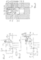
- a tractor vehicle is shown at 10 and a trailer at 11.
- the trailer is a conventional full trailer having a front axle with wheels at opposite ends thereof and a rear axle, again with wheels at opposite ends thereof.
- the wheels on the front axle each have a brake, the brakes being operated by brake actuators 12 a , 12 b respectively.
- the rear wheels also each have a brake, the brakes being operated by a brake actuator 13 a and a brake actuator 13 b .
- the brake actuators 12 a 12 b , and 13 a , 13 b are responsive to brake pressure, in the present example compressed air, supplied thereto as hereinafter to be described by the brake system.
- the brake system also has a reservoir 14 and air is supplied to the reservoir by a main air supply line 15 which is provided with suitable couplings 16 between the tractor and the trailer.
- a fluid pressure brake demand signal is generated on the tractor by the operator's brake pedal 17 in conventional manner and is fed by suitable couplings 18 and a fluid pressure brake demand signal supply line 19 to a pressure transducer 20 associated with an electronic control unit 21 but which may be provided separate therefrom at a desired location and connected to the control unit 21 via an electrical line.
- the transducer 20 is responsive to the fluid pressure brake demand signal provided on the line 19 and supplies a corresponding electrical brake demand signal to the controller 21.
- the controller 21 provides an electrical brake operating signal on electrical lines 32a and 32b to two electro-pneumatic relay valves (EPRV) 33 and 34.
- EPRV electro-pneumatic relay valves
- the controller 21 is also associated with two further pressure transducers 22, 23 which are responsive to pressure from a front air suspension 24 and a rear air suspension 25 of the vehicle so that the controller is responsive to variation in load imposed on the front and rear suspensions.
- the controller 21 is also provided with electrical signals on lines from wheel speed sensors 29-29 a -30-31 associated with each of the front wheels and each of the rear wheels respectively.
- the controller 21 provides electrical brake operating signals on electrical lines 32 a and 32 b in accordance with driver brake demand as indicated by the fluid pressure brake demand signal modulated as necessary according to the programming of the electronic control unit by the load imposed from the front and rear suspensions 24, 25 and by skid conditions of the wheels of the front axle or each of the wheels of the rear axle sensed by the speed sensors 29, 29 a , 30, 31.
- the EPRV 33 supplies brake pressure to both of the actuators, 12 a , 12 b , of the front axle.
- the EPRV 33 provides brake pressure to the actuators 12 a , 12 b which is modulated not only in accordance with anti-skid requirements but also in accordance with the front axle load of the trailer.
- the controller 21 also provides on lines 32 b an electrical brake operating signal to the EPRV 34 which modulates the pressure fed therefrom only in accordance with the rear axle load of the trailer.
- the controller 21 also provides an electrical brake operating signal to the ABS valve 35 on line 32 c and a separate electrical brake operating signal on line 32 d to the ABS valve 36.
- the brake pressure supplied to the actuators 13 a , 13 b respectively is modulated by the associated ABS valves 35, 36 in accordance with anti-skid requirements.
- Each EPRV 33-34 and ABS valves 35-36 is similar and comprises an electrically operable valve means and a supply valve means.
- the supply valve means in this example comprises a conventional relay valve 40 to which main air supply is fed from the reservoir 14 on a respective line 41-43.
- the magnitude of the air pressure at the exit port of each relay valve 40 is modulated by the relay valve in accordance with a fluid pressure brake operating signal fed to the relay valve on line 44 from the electrically operable valve means which comprises a pair of solenoid valves a , b .
- Air is fed to the solenoid valves a - b of each EPRV 33-34 and ABS valves 35-36 on lines 45, 46, 47 a and 47b respectively.
- the lines 47 a and 47 b branch from a line 47 which is connected to the output of the relay valve 40 of the EPRV 34. Hence the fluid pressure brake operating signal fed on the lines 44 to the relay valves 40 of the ABS valves 35 and 36 is, at all times, air which has been supplied from the reservoir 14 on line 42 via the EPRV 34.
- the fluid pressure brake operating signal may be supplied from the reservoir 14 or may be supplied from the fluid pressure brake demand signal depending upon the operating condition of the brake system as hereafter to be described.
- an emergency supply valve (ESV) 50 which, in the present example, includes a manoeuvring valve 51 of conventional kind connected in series only with the EPRV 33 for the brakes of the front axle. Since the manoeuvring valve operates in a conventional manner further discussion thereof is not necessary.
- the ESV 50 includes a combined electrically operable and pressure operable valve which provides a demand signal control valve and an emergency valve operable in the event of failure in pressure supply to the brake system on line 15.
- the combined valve is indicated generally at 52 and has a first inlet 53 connected to the main supply line 15 upstream of a one-way check valve 54 which is disposed upstream of the reservoir 14 so as to prevent air from reservoir 14 and the remainder of the brake system downstream of the check valve 54 exhausting to atmosphere in the event of failure in the pipe 15 or upstream thereof.
- the valve 52 has a second inlet 55 which is connected by a line 56 to the reservoir 14.
- a third inlet port 57 of the valve 52 is connected by a line 58 incorporating a quick release one-way exhaust valve 59 to the fluid pressure brake demand signal supply line 19.
- An outlet port 60 of the valve 52 is connected by line 61 to the line 45 and to the line 46 which provides an input to the solenoid valves a , b of the EPRV's 33, 34.
- valve 52 comprises a valve body 62 in which the first to third inlet ports 53, 55, 57 and outlet port 60 are provided.
- the first inlet port 53 communicates with a first chamber 64 in which a piston 65 is slidably mounted the piston being biased by a coil compression spring 66 upward, as viewed in Figure 4 in a first direction.
- the part of the chamber 64 below the piston 65 is connected to atmosphere through an exhaust port 67.
- the piston 65 has a piston rod 68 which passes through a passage 69 in a one-way valve member 70 which is biased by coil compression springs 71 into engagement with a valve seat 72 so as to prevent communication between the second inlet port and the first inlet port whilst permitting communication between the first inlet port and the second inlet port when the pressure differential therebetween overcomes the bias of the spring 71.
- any other pressure responsive member may be provided, such as a diaphragm.
- the piston rod 68 is adapted to engage a valve member 72 a which is movably mounted in a second chamber 73.
- the valve member 72A comprises the armature of a solenoid the coil of which is indicated at 74 and the valve 72 a is normally biased downwardly in Figure 4 by a coil compression spring 75 to a first position.
- the valve member 72 a is provided with a sealing member 76 for sealing engagement with a valve seat 77 to obstruct flow of air from the second inlet port 55 into the chamber 73.
- valve member 72 a At its upper end the valve member 72 a is provided with a further sealing member 78 for sealing engagement with a second valve seat 79 to prevent communication between the third inlet port 57 and the chamber 73 when the valve member 72 a is in a second position.
- the chamber 73 is in constant communication with the outlet port 60.
- the system In use, during normal operation when air under pressure is supplied from the tractor 10 by the couplings 16 to the supply line 15 at normal pressure and when a normal electrical supply is provided to the brake system, ie a permanent supply such as ISO 7638 on line 80 or stop lightpower according to ISO 1185 on line 81 the system operates as follows. In the presence of electrical supply when the driver demands the application of the brakes the transducer 20 monitors the magnitude of the fluid pressure brake demand signal on the line 19 and causes the solenoid coil 74 to be energised to move the valve member 72 a to the second position to block the passage of the brake pressure demand signal from the third inlet 57 to the outlet 60 and to permit flow of air from the reservoir 14 via line 56 and second inlet port 55 to the outlet 60.
- a permanent supply such as ISO 7638 on line 80 or stop lightpower according to ISO 1185 on line 81
- reservoir air is supplied on lines 45 and 46 to the solenoid valves a , b of the EPRV's 33, 34 to provide a brake pressure operating signal to the associated relay valve 40 thereby modulating the reservoir pressure on the lines 41 and 42 to provide the desired brake pressure.
- the valves a , b of the EPRV 33 modulate the air supply line 45 to accordingly provide brake pressure which is modulated for ABS control.
- the solenoid valves a , b of the EPRV 34 similarly modulate the air from the reservoir 14 in the line 46 in accordance with the rear axle load of the trailer.
- the output from the EPRV 34 is fed on lines 47 a , 47 b to provide the control input air for the solenoid valves a , b of the ABS valves 35, 36 which modulate the control pressure in accordance with anti-skid control to provide an appropriately modulated brake pressure to the actuators 13 a , 13 b .
- valve number 78 will remain in the first position shown in Figure 4 under the bias of the spring 75 so that reservoir air from reservoir 14 supplied to the inlet port 55 will be blocked from flow to the outlet 60 whilst the fluid pressure brake demand signal will alternatively be fed from the third inlet 57 to the outlet 60 and thus provide the control air on lines 45, 46 to the control solenoids, a , b to the EPRV valves 33, 34. Since the electrical system is inoperative, these valves will remain in their first spring biased position illustrated in Figure 1 and will pass the fluid pressure brake demand signal therethrough to provide a control signal to their associated relay valves. Otherwise, operation is as described before.
- the reservoir air is fed directly, without modulation, to the control side of the relay valves 40 of the EPRV's 33, 34 and hence reservoir air is fed, without modulation, to provide the control air for the solenoid valves a , b of the ABS valves 35, 36 so that, again, reservoir air is fed by the solenoid valves, without modulation, to the actuators 13 a , 13 b .
- solenoid valves a and b are configured as described and illustrated hereinbefore, if desired the solenoid valves may be alternatively configured so as to provide control pressure supply, hold and exhaust modes in conventional manner and as described for example in GB-A-2131508.
- Figure 3 shows a further modification in which the fluid pressure brake demand signal, instead of being fed into the third port 57, is fed to a first inlet 90 of a selector valve 91 such as a shuttle valve, having a valve member movable in dependence on the pressure difference between the inlets to select between connecting the first inlet or the second inlet to the outlet.
- the second inlet 92 of the shuttle valve is connected to the outlet 60 (of course, in this embodiment no inlet corresponding to the third inlet 57 of the previously described embodiments is provided).
- An outlet 93 of the selector valve 91 is connected to line 61 and in other respects the device is as described previously.
- the modified valve 52 when energised permits reservoir air to pass to the second inlet 92 to close the first inlet 90 of the selector valve 91 so that reservoir air is fed to line 61 and hence downstream thereof as described in connection with the first embodiment.
- the modified valve 52 When electrical supply fails the modified valve 52 will revert to the position shown in Figure 3 so that reservoir 14 is blocked and the second inlet 92 is connected to exhaust as shown at 94. As a result, the fluid pressure brake demand signal supplied to the first inlet 90 on line 58 will be fed to line 61 and hence downstream thereof so that the system operates in the same way as described hereinbefore in connection with Figure 1. It will be appreciated that in Figure 3 the modified valve 52 achieves the same function as the valve 52 described in connection with Figures 1 and 2 but relies upon the presence of the selector valve 91 rather than controlling the supply of fluid pressure brake demand signal directly by the valve member 72 a .
- the hereabove described brake systems may be utilised in a semi-trailer having only a rear axle.
- the EPRV 33 feeds brake pressure to a brake actuator for one of the wheels of the rear axle whilst the EPRV 34 feeds brake pressure to the actuator for the other wheel of the rear axle.
- the controller 21 is programmed so as to provide load sensitive and anti-skid control for both EPRV's.
- the ABS valves 35 and 36 are not provided.
Description
Claims (18)
- A brake system for a trailer vehicle (11) comprising, provided on the trailer vehicle, a trailer fluid pressure supply system comprising a reservoir (14) and a coupling (16) connectable to a fluid pressure outlet of a tractor vehicle, transducer means (20) responsive to a fluid pressure brake demand signal, delivered to the transducer means (20) from a further coupling (18) connectable to a fluid pressure brake demand signal outlet of the tractor vehicle, to provide an electrical brake demand signal; electronic control means (21) responsive to the electrical brake demand signal to provide an electrical brake operating signal; a brake valve means (33) responsive to said electrical brake operating signal for brake application; said brake valve means (33) comprising a supply valve means (40) and an electrically operable valve means (33a, 34b) having an inlet and an outlet and responsive to said electrical brake operating signal to provide, at said electrically operable valve outlet, a fluid pressure brake operating signal which is dependant on said fluid pressure brake demand signal; means to connect said electrically operable valve outlet to a fluid pressure brake operating signal inlet of the supply valve means and said supply valve means (40) being responsive to said fluid pressure brake operating signal to supply fluid from said source to at least one actuator (12a, 12b)for brake application under a brake pressure controlled by said supply valve means (40) in accordance with the said received fluid pressure brake operating signal and an electrically operable demand signal control valve (52) responsive to presence or absence of electrical supply to said system respectively to prevent or to permit delivery of said fluid pressure brake demand signal to the supply valve means (40) to provide an alternative fluid brake operating signal for the supply valve means, and a pressure responsive emergency valve (50) to connect said reservoir (14) to the supply valve means (40) to provide an alternative fluid pressure brake operating signal therefor when the pressure in the supply to said reservoir (14) falls below a predetermined value, characterised in that said brake system has a combined electrically operable demand signal control valve and emergency valve (50) comprising a first inlet (53) connected to the supply line, a second inlet (55) connected to the reservoir (14) and an outlet (60) connectable to the fluid pressure brake operating signal inlet of the supply valve means, a valve member (72a) to control flow of fluid between the second inlet (55) and the outlet (60) and said valve member (72a) being moveable by electrical means responsive to said presence or absence of electrical supply to the system and by fluid pressure means (68) responsive to said pressure in the supply falling below said predetermined value.
- A brake system according to Claim 1 where the combined valve (50) has a third inlet (57) to which the fluid pressure brake demand signal is supplied.
- A brake system according to Claim 1 or 2 where the outlet (60) is connected to the fluid pressure brake operating signal inlet of the supply valve means.
- A braking system according to Claim 1 where the outlet of the combined valve is connected to one inlet (92) of a selector valve (91) which has a second inlet (90) to which the fluid pressure brake demand signal is supplied and an outlet (93) connected to the fluid pressure brake operating signal inlet of the supply valve means (40) and means to select between connection of the first inlet (92) or the second inlet (90) to the outlet (93) according to the pressure difference between the first and second inlets.
- A brake system according to any one of the preceding claims wherein the valve member (72a) is movable between a first position in which it prevents flow between the second inlet (55) and the outlet (60) and a second position in which it permits flow between the second inlet (55) at the outlet (60).
- A brake system according to Claim 2 or any one of Claims 3 to 5 where dependant on Claim 2 where the valve member (72a) when in the first position may permit flow between the third inlet (57) and the outlet (60) whilst when in the second position may prevent flow between the third inlet (57) and the outlet (60).
- A valve (52) for use in a brake system said valve comprising a first inlet (53), a second inlet (55) and an outlet (60), a valve member (72a) to control flow of fluid pressure between the second inlet (55) and the outlet (60) and said valve member (72a) being movable by electrical means and by fluid pressure means, said valve member being biased to a first position in which it prevents fluid flow between the second inlet and the outlet and being movable to a second position by said fluid pressure means to a second position in which it permits fluid flow between said second inlet and said outlet characterised in that said fluid pressure means is operable to move said valve member to said second position in response to pressure at said first inlet (53) falling below a predetermined value.
- A valve according to Claim 7 where the valve has a third inlet.
- A valve according to Claim 7 where the outlet of the valve is connected to one inlet (92) of a selector valve (91) which has a second inlet (90) and an outlet (93) and means to select between connection of the first inlet (92) or second inlet (90) to the outlet (93) according to the pressure difference between the first and second inlets.
- A valve according to any one of Claims 7 to 9 where the valve member (72a) is moveable between the first position and the second position by said electrical means.
- A valve according to Claim 8 or Claim 10 where dependant on Claim 8 where the valve member (72a) when in the first position may permit flow between the third inlet (57) and the outlet (60) when in the second position may prevent flow between the third inlet (57) and the outlet (60).
- A brake system according to Claims 1 to 6 or a valve according to Claims 7 to 11 where said electrical means comprises a solenoid.
- A brake system according to Claims 1 to 6 or Claim 12 or a valve system according to Claims 7 to 11 or Claim 12 where said fluid pressure means comprises a pressure responsive member (65) moveable in a chamber (64) which is in communication with said first inlet (53) so as to move in a first direction when the pressure at the first inlet (53) falls below a predetermined pressure and there being an element (68) moveable with the pressure responsive member (65) to cause movement of the valve member (72a).
- A brake system or a valve according to Claim 13 where the pressure responsive member is a piston.
- A brake system or a valve according to Claim 13 where the pressure responsive member is a diaphragm.
- A brake system or a valve according to any one of Claims 13 to 15 where said element (68) is about to move the valve member to said second position on movement of the element in said first direction.
- A brake system or valve according to Claim 16 where said element (68) is permitted to move away from the valve member (72a) as a result of movement of the element in the opposite direction.
- A brake system according to any one of the claims 1-6, 12-17 or a valve according to any one of the claims 7-11, 12-17 wherein a non-return valve means (70) is provided to permit flow between the first inlet and the second inlet and prevent flow from the second inlet to the first inlet.
Applications Claiming Priority (3)
| Application Number | Priority Date | Filing Date | Title |
|---|---|---|---|
| GBGB9610068.0A GB9610068D0 (en) | 1996-05-14 | 1996-05-14 | Brake system for a trailer vehicle and a valve for use therein |
| GB9610068 | 1996-05-14 | ||
| PCT/GB1997/001275 WO1997043155A1 (en) | 1996-05-14 | 1997-05-13 | Brake system for a trailer vehicle and a valve for use therein |
Publications (2)
| Publication Number | Publication Date |
|---|---|
| EP0837806A1 EP0837806A1 (en) | 1998-04-29 |
| EP0837806B1 true EP0837806B1 (en) | 2001-08-08 |
Family
ID=10793684
Family Applications (1)
| Application Number | Title | Priority Date | Filing Date |
|---|---|---|---|
| EP97920881A Expired - Lifetime EP0837806B1 (en) | 1996-05-14 | 1997-05-13 | Brake system for a trailer vehicle and a valve for use therein |
Country Status (9)
| Country | Link |
|---|---|
| US (1) | US6079790A (en) |
| EP (1) | EP0837806B1 (en) |
| JP (1) | JP4156031B2 (en) |
| AU (1) | AU2709597A (en) |
| BR (1) | BR9702212A (en) |
| DE (1) | DE69706017T2 (en) |
| ES (1) | ES2162286T3 (en) |
| GB (1) | GB9610068D0 (en) |
| WO (1) | WO1997043155A1 (en) |
Families Citing this family (21)
| Publication number | Priority date | Publication date | Assignee | Title |
|---|---|---|---|---|
| DE19928113C1 (en) * | 1999-06-19 | 2000-10-26 | Haldex Brake Prod Gmbh | Trailer brake valve for anti-lock compressed air trailer braking system has independent control electronics driving valve in brake line, valve for controlled venting of control chamber |
| DE10137148A1 (en) * | 2001-07-30 | 2003-02-13 | Knorr Bremse Systeme | Braking circuit for commercial vehicle trailer with steered front axle has anti-blocking braking valve for rear braking cylinders controlled in dependence on differential slip |
| US6655750B2 (en) | 2001-10-19 | 2003-12-02 | Meritor Wabco Vehicle Control Systems | Combination inversion and relay or quick release valve assembly |
| ITTO20011201A1 (en) * | 2001-12-21 | 2003-06-21 | Knorr Bremse Systeme | BRAKING SYSTEM FOR A TRAILER VEHICLE. |
| DE10301096A1 (en) * | 2003-01-14 | 2004-08-05 | Wabco Gmbh & Co. Ohg | Method for driving dynamics control for a vehicle train |
| AU2004215405B2 (en) * | 2003-02-24 | 2010-06-24 | Bendix Commercial Vehicle Systems Llc | Electro-pneumatic latching valve system |
| US7354118B2 (en) * | 2005-02-25 | 2008-04-08 | Bendix Commercial Vehicle Systems, Inc. | Control valve system |
| AU2012201087B2 (en) * | 2006-05-12 | 2014-01-09 | Bendix Commercial Vehicle Systems Llc | Service work brake arrangement, method, system |
| US7690735B2 (en) * | 2006-05-12 | 2010-04-06 | Bendix Commercial Vehicle Systems Llc | Service work brake arrangement |
| GB0615837D0 (en) * | 2006-08-09 | 2006-09-20 | Univ Cambridge Tech | Air braking system |
| DE102006041012A1 (en) * | 2006-08-31 | 2008-03-06 | Wabco Gmbh | Valve unit, brake control device, vehicle brake system and vehicle |
| DE102007002020A1 (en) | 2007-01-13 | 2008-07-17 | Wabco Gmbh | Towing vehicle brake and air suspension system |
| DE102008022026A1 (en) * | 2008-05-02 | 2009-11-05 | Wabco Gmbh | EBS system for drawbar trailers |
| GB0813822D0 (en) * | 2008-07-29 | 2008-09-03 | Knorr Bremse Systeme | Trailer electronic breaking system |
| DE102009059900A1 (en) * | 2009-12-21 | 2011-06-22 | Knorr-Bremse Systeme für Nutzfahrzeuge GmbH, 80809 | Valve means, electrically operated parking brake system and method of controlling an electrically actuated parking brake system |
| DE102011011634B4 (en) * | 2011-02-17 | 2012-12-06 | Knorr-Bremse Systeme für Nutzfahrzeuge GmbH | Compressed air supply device for commercial vehicles |
| EP3353027B1 (en) * | 2015-09-23 | 2021-05-12 | AGCO International GmbH | A vehicle trailer brake system and method |
| DE102016205125A1 (en) * | 2016-03-29 | 2017-10-05 | Siemens Aktiengesellschaft | Brake system, rail vehicle with a braking system and method for operating a brake system |
| WO2018056971A1 (en) * | 2016-09-22 | 2018-03-29 | Newyork Air Brake, Llc | Electronically controlled pneumatic (ecp) overlay control valve |
| EP3691941B1 (en) * | 2017-10-04 | 2021-07-07 | Volvo Lastvagnar AB | By-pass of air supply protection for electronic parking brake system and vehicle comprising such system |
| CN108725418A (en) * | 2018-06-15 | 2018-11-02 | 江苏柳工机械有限公司 | The urgent auxiliary braking system of engineering truck |
Citations (1)
| Publication number | Priority date | Publication date | Assignee | Title |
|---|---|---|---|---|
| WO1997032767A1 (en) * | 1996-03-09 | 1997-09-12 | Robert Bosch Gmbh | Trailer control valve for a motor-vehicle compressed-air brake system |
Family Cites Families (12)
| Publication number | Priority date | Publication date | Assignee | Title |
|---|---|---|---|---|
| DE3327888A1 (en) * | 1983-08-02 | 1985-02-14 | Knorr-Bremse GmbH, 8000 München | CONTROL VALVE FOR AIR BRAKES OF RAIL VEHICLES |
| US4638837A (en) * | 1984-11-13 | 1987-01-27 | Allied Corporation | Electro/pneumatic proportional valve |
| DE3514949A1 (en) * | 1985-04-25 | 1986-10-30 | Wabco Westinghouse Fahrzeugbremsen GmbH, 3000 Hannover | PRESSURE BRAKE SYSTEM FOR THE TRAILER OF A VEHICLE |
| US4755008A (en) * | 1985-12-25 | 1988-07-05 | Nippondenso Co., Ltd. | Braking system with power brake, braking force proportioning, anti-skid, and traction control functions |
| DE4030981A1 (en) * | 1990-10-01 | 1992-04-02 | Bosch Gmbh Robert | ELECTRIC PNEUMATIC TRAILER BRAKE SYSTEM |
| US5222788A (en) * | 1991-09-16 | 1993-06-29 | Westinghouse Air Brake Company | Microprocessor based electro-pneumatic locomotive brake control system having brake assurance circuit |
| JPH0680064A (en) * | 1992-07-13 | 1994-03-22 | Sumitomo Electric Ind Ltd | Fluid pressure control device |
| ES2096213T3 (en) * | 1992-09-03 | 1997-03-01 | Grau Ltd | BREAK SYSTEM. |
| GB2270355B (en) * | 1992-09-03 | 1995-10-04 | Grau Ltd | Braking systems |
| FR2701531B1 (en) * | 1993-02-12 | 1995-04-28 | Alliedsignal Europ Services | Proportional pneumatic solenoid valve. |
| US5615929A (en) * | 1993-11-17 | 1997-04-01 | Grau Limited | Brake system for a vehicle train |
| US5881768A (en) * | 1997-03-31 | 1999-03-16 | Westinghouse Air Brake Company | Combination motor/pneumatic driven train brake pipe pressure exhaust valve |
-
1996
- 1996-05-14 GB GBGB9610068.0A patent/GB9610068D0/en active Pending
-
1997
- 1997-05-13 WO PCT/GB1997/001275 patent/WO1997043155A1/en active IP Right Grant
- 1997-05-13 US US08/981,763 patent/US6079790A/en not_active Expired - Lifetime
- 1997-05-13 DE DE69706017T patent/DE69706017T2/en not_active Expired - Lifetime
- 1997-05-13 BR BR9702212A patent/BR9702212A/en not_active IP Right Cessation
- 1997-05-13 EP EP97920881A patent/EP0837806B1/en not_active Expired - Lifetime
- 1997-05-13 AU AU27095/97A patent/AU2709597A/en not_active Abandoned
- 1997-05-13 JP JP54064497A patent/JP4156031B2/en not_active Expired - Fee Related
- 1997-05-13 ES ES97920881T patent/ES2162286T3/en not_active Expired - Lifetime
Patent Citations (1)
| Publication number | Priority date | Publication date | Assignee | Title |
|---|---|---|---|---|
| WO1997032767A1 (en) * | 1996-03-09 | 1997-09-12 | Robert Bosch Gmbh | Trailer control valve for a motor-vehicle compressed-air brake system |
Non-Patent Citations (1)
| Title |
|---|
| A.SCHMITT: "Der Hydraulik Trainer", November 1980, G.L.REXROTH GMBH, LOHR AM MAIN * |
Also Published As
| Publication number | Publication date |
|---|---|
| DE69706017T2 (en) | 2001-11-22 |
| JP4156031B2 (en) | 2008-09-24 |
| DE69706017D1 (en) | 2001-09-13 |
| ES2162286T3 (en) | 2001-12-16 |
| US6079790A (en) | 2000-06-27 |
| WO1997043155A1 (en) | 1997-11-20 |
| EP0837806A1 (en) | 1998-04-29 |
| AU2709597A (en) | 1997-12-05 |
| BR9702212A (en) | 1999-07-20 |
| JPH11509807A (en) | 1999-08-31 |
| GB9610068D0 (en) | 1996-07-17 |
Similar Documents
| Publication | Publication Date | Title |
|---|---|---|
| EP0837806B1 (en) | Brake system for a trailer vehicle and a valve for use therein | |
| US5443306A (en) | Electrohydraulic brake control system | |
| JP2801130B2 (en) | Brake system | |
| US5042883A (en) | Trailer braking system for a towing vehicle | |
| US5615929A (en) | Brake system for a vehicle train | |
| US4861115A (en) | Electrically-controlled motor vehicle brake system | |
| US4919492A (en) | Multiple-circuit brake system | |
| EP2750945B1 (en) | Vehicle braking system | |
| US5294190A (en) | Brake system with at least one brake circuit | |
| US5586813A (en) | Electro-pneumatic freight brake control system | |
| GB2176857A (en) | Electropneumatic brake system for a railway vehicle | |
| CA2174910C (en) | Pneumatic empty/load proportioning for electro-pneumatic brake | |
| US20220227342A1 (en) | Electropneumatic control module | |
| US5277485A (en) | Vehicle braking system | |
| EP0825940B1 (en) | Vehicle braking system with drive wheel slip control | |
| EP0956227B1 (en) | Pneumatically-operated braking system for tractor-trailer combinations | |
| WO1991011353A1 (en) | Vehicle braking system | |
| GB2270355A (en) | Braking systems | |
| EP4227172A1 (en) | Trailer control module and trailer control valve arrangement | |
| JPH11505788A (en) | Vehicle brake system | |
| EP0516348A2 (en) | Fluid pressure modulator valve apparatus |
Legal Events
| Date | Code | Title | Description |
|---|---|---|---|
| PUAI | Public reference made under article 153(3) epc to a published international application that has entered the european phase |
Free format text: ORIGINAL CODE: 0009012 |
|
| 17P | Request for examination filed |
Effective date: 19971229 |
|
| AK | Designated contracting states |
Kind code of ref document: A1 Designated state(s): BE DE ES FR IT SE |
|
| RAP1 | Party data changed (applicant data changed or rights of an application transferred) |
Owner name: HALDEX BRAKE PRODUCTS LIMITED |
|
| 17Q | First examination report despatched |
Effective date: 19990507 |
|
| GRAG | Despatch of communication of intention to grant |
Free format text: ORIGINAL CODE: EPIDOS AGRA |
|
| GRAG | Despatch of communication of intention to grant |
Free format text: ORIGINAL CODE: EPIDOS AGRA |
|
| GRAG | Despatch of communication of intention to grant |
Free format text: ORIGINAL CODE: EPIDOS AGRA |
|
| GRAG | Despatch of communication of intention to grant |
Free format text: ORIGINAL CODE: EPIDOS AGRA |
|
| GRAH | Despatch of communication of intention to grant a patent |
Free format text: ORIGINAL CODE: EPIDOS IGRA |
|
| RBV | Designated contracting states (corrected) |
Designated state(s): BE DE ES FR IT SE |
|
| GRAH | Despatch of communication of intention to grant a patent |
Free format text: ORIGINAL CODE: EPIDOS IGRA |
|
| GRAA | (expected) grant |
Free format text: ORIGINAL CODE: 0009210 |
|
| AK | Designated contracting states |
Kind code of ref document: B1 Designated state(s): BE DE ES FR IT SE |
|
| RAP1 | Party data changed (applicant data changed or rights of an application transferred) |
Owner name: HALDEX BRAKE PRODUCTS LIMITED |
|
| REF | Corresponds to: |
Ref document number: 69706017 Country of ref document: DE Date of ref document: 20010913 |
|
| ITF | It: translation for a ep patent filed |
Owner name: RACHELI & C. S.R.L. |
|
| ET | Fr: translation filed | ||
| REG | Reference to a national code |
Ref country code: ES Ref legal event code: FG2A Ref document number: 2162286 Country of ref document: ES Kind code of ref document: T3 |
|
| PLBE | No opposition filed within time limit |
Free format text: ORIGINAL CODE: 0009261 |
|
| STAA | Information on the status of an ep patent application or granted ep patent |
Free format text: STATUS: NO OPPOSITION FILED WITHIN TIME LIMIT |
|
| 26N | No opposition filed | ||
| PGFP | Annual fee paid to national office [announced via postgrant information from national office to epo] |
Ref country code: SE Payment date: 20040506 Year of fee payment: 8 |
|
| PGFP | Annual fee paid to national office [announced via postgrant information from national office to epo] |
Ref country code: ES Payment date: 20040518 Year of fee payment: 8 |
|
| PGFP | Annual fee paid to national office [announced via postgrant information from national office to epo] |
Ref country code: BE Payment date: 20040716 Year of fee payment: 8 |
|
| PG25 | Lapsed in a contracting state [announced via postgrant information from national office to epo] |
Ref country code: IT Free format text: LAPSE BECAUSE OF NON-PAYMENT OF DUE FEES Effective date: 20050513 |
|
| PG25 | Lapsed in a contracting state [announced via postgrant information from national office to epo] |
Ref country code: SE Free format text: LAPSE BECAUSE OF NON-PAYMENT OF DUE FEES Effective date: 20050514 Ref country code: ES Free format text: LAPSE BECAUSE OF NON-PAYMENT OF DUE FEES Effective date: 20050514 |
|
| PG25 | Lapsed in a contracting state [announced via postgrant information from national office to epo] |
Ref country code: BE Free format text: LAPSE BECAUSE OF NON-PAYMENT OF DUE FEES Effective date: 20050531 |
|
| BERE | Be: lapsed |
Owner name: *HALDEX BRAKE PRODUCTS LTD Effective date: 20050531 |
|
| EUG | Se: european patent has lapsed | ||
| REG | Reference to a national code |
Ref country code: ES Ref legal event code: FD2A Effective date: 20050514 |
|
| BERE | Be: lapsed |
Owner name: *HALDEX BRAKE PRODUCTS LTD Effective date: 20050531 |
|
| REG | Reference to a national code |
Ref country code: FR Ref legal event code: PLFP Year of fee payment: 20 |
|
| PGFP | Annual fee paid to national office [announced via postgrant information from national office to epo] |
Ref country code: DE Payment date: 20160510 Year of fee payment: 20 |
|
| PGFP | Annual fee paid to national office [announced via postgrant information from national office to epo] |
Ref country code: FR Payment date: 20160412 Year of fee payment: 20 |
|
| REG | Reference to a national code |
Ref country code: DE Ref legal event code: R071 Ref document number: 69706017 Country of ref document: DE |