EP2750945B1 - Vehicle braking system - Google Patents
Vehicle braking system Download PDFInfo
- Publication number
- EP2750945B1 EP2750945B1 EP12707894.7A EP12707894A EP2750945B1 EP 2750945 B1 EP2750945 B1 EP 2750945B1 EP 12707894 A EP12707894 A EP 12707894A EP 2750945 B1 EP2750945 B1 EP 2750945B1
- Authority
- EP
- European Patent Office
- Prior art keywords
- valve
- braking
- actuator
- control
- brake
- Prior art date
- Legal status (The legal status is an assumption and is not a legal conclusion. Google has not performed a legal analysis and makes no representation as to the accuracy of the status listed.)
- Active
Links
- 239000012530 fluid Substances 0.000 claims description 67
- 230000001010 compromised effect Effects 0.000 claims description 5
- 238000000034 method Methods 0.000 claims description 3
- 230000001133 acceleration Effects 0.000 description 1
- 238000011144 upstream manufacturing Methods 0.000 description 1
Images


Classifications
-
- B—PERFORMING OPERATIONS; TRANSPORTING
- B60—VEHICLES IN GENERAL
- B60T—VEHICLE BRAKE CONTROL SYSTEMS OR PARTS THEREOF; BRAKE CONTROL SYSTEMS OR PARTS THEREOF, IN GENERAL; ARRANGEMENT OF BRAKING ELEMENTS ON VEHICLES IN GENERAL; PORTABLE DEVICES FOR PREVENTING UNWANTED MOVEMENT OF VEHICLES; VEHICLE MODIFICATIONS TO FACILITATE COOLING OF BRAKES
- B60T8/00—Arrangements for adjusting wheel-braking force to meet varying vehicular or ground-surface conditions, e.g. limiting or varying distribution of braking force
- B60T8/17—Using electrical or electronic regulation means to control braking
- B60T8/1755—Brake regulation specially adapted to control the stability of the vehicle, e.g. taking into account yaw rate or transverse acceleration in a curve
-
- B—PERFORMING OPERATIONS; TRANSPORTING
- B60—VEHICLES IN GENERAL
- B60T—VEHICLE BRAKE CONTROL SYSTEMS OR PARTS THEREOF; BRAKE CONTROL SYSTEMS OR PARTS THEREOF, IN GENERAL; ARRANGEMENT OF BRAKING ELEMENTS ON VEHICLES IN GENERAL; PORTABLE DEVICES FOR PREVENTING UNWANTED MOVEMENT OF VEHICLES; VEHICLE MODIFICATIONS TO FACILITATE COOLING OF BRAKES
- B60T13/00—Transmitting braking action from initiating means to ultimate brake actuator with power assistance or drive; Brake systems incorporating such transmitting means, e.g. air-pressure brake systems
- B60T13/10—Transmitting braking action from initiating means to ultimate brake actuator with power assistance or drive; Brake systems incorporating such transmitting means, e.g. air-pressure brake systems with fluid assistance, drive, or release
- B60T13/66—Electrical control in fluid-pressure brake systems
- B60T13/68—Electrical control in fluid-pressure brake systems by electrically-controlled valves
-
- B—PERFORMING OPERATIONS; TRANSPORTING
- B60—VEHICLES IN GENERAL
- B60T—VEHICLE BRAKE CONTROL SYSTEMS OR PARTS THEREOF; BRAKE CONTROL SYSTEMS OR PARTS THEREOF, IN GENERAL; ARRANGEMENT OF BRAKING ELEMENTS ON VEHICLES IN GENERAL; PORTABLE DEVICES FOR PREVENTING UNWANTED MOVEMENT OF VEHICLES; VEHICLE MODIFICATIONS TO FACILITATE COOLING OF BRAKES
- B60T7/00—Brake-action initiating means
- B60T7/02—Brake-action initiating means for personal initiation
-
- B—PERFORMING OPERATIONS; TRANSPORTING
- B60—VEHICLES IN GENERAL
- B60T—VEHICLE BRAKE CONTROL SYSTEMS OR PARTS THEREOF; BRAKE CONTROL SYSTEMS OR PARTS THEREOF, IN GENERAL; ARRANGEMENT OF BRAKING ELEMENTS ON VEHICLES IN GENERAL; PORTABLE DEVICES FOR PREVENTING UNWANTED MOVEMENT OF VEHICLES; VEHICLE MODIFICATIONS TO FACILITATE COOLING OF BRAKES
- B60T7/00—Brake-action initiating means
- B60T7/12—Brake-action initiating means for automatic initiation; for initiation not subject to will of driver or passenger
- B60T7/20—Brake-action initiating means for automatic initiation; for initiation not subject to will of driver or passenger specially for trailers, e.g. in case of uncoupling of or overrunning by trailer
-
- B—PERFORMING OPERATIONS; TRANSPORTING
- B60—VEHICLES IN GENERAL
- B60T—VEHICLE BRAKE CONTROL SYSTEMS OR PARTS THEREOF; BRAKE CONTROL SYSTEMS OR PARTS THEREOF, IN GENERAL; ARRANGEMENT OF BRAKING ELEMENTS ON VEHICLES IN GENERAL; PORTABLE DEVICES FOR PREVENTING UNWANTED MOVEMENT OF VEHICLES; VEHICLE MODIFICATIONS TO FACILITATE COOLING OF BRAKES
- B60T8/00—Arrangements for adjusting wheel-braking force to meet varying vehicular or ground-surface conditions, e.g. limiting or varying distribution of braking force
- B60T8/17—Using electrical or electronic regulation means to control braking
- B60T8/1701—Braking or traction control means specially adapted for particular types of vehicles
- B60T8/1708—Braking or traction control means specially adapted for particular types of vehicles for lorries or tractor-trailer combinations
-
- B—PERFORMING OPERATIONS; TRANSPORTING
- B60—VEHICLES IN GENERAL
- B60T—VEHICLE BRAKE CONTROL SYSTEMS OR PARTS THEREOF; BRAKE CONTROL SYSTEMS OR PARTS THEREOF, IN GENERAL; ARRANGEMENT OF BRAKING ELEMENTS ON VEHICLES IN GENERAL; PORTABLE DEVICES FOR PREVENTING UNWANTED MOVEMENT OF VEHICLES; VEHICLE MODIFICATIONS TO FACILITATE COOLING OF BRAKES
- B60T8/00—Arrangements for adjusting wheel-braking force to meet varying vehicular or ground-surface conditions, e.g. limiting or varying distribution of braking force
- B60T8/17—Using electrical or electronic regulation means to control braking
- B60T8/1755—Brake regulation specially adapted to control the stability of the vehicle, e.g. taking into account yaw rate or transverse acceleration in a curve
- B60T8/17554—Brake regulation specially adapted to control the stability of the vehicle, e.g. taking into account yaw rate or transverse acceleration in a curve specially adapted for enhancing stability around the vehicles longitudinal axle, i.e. roll-over prevention
-
- B—PERFORMING OPERATIONS; TRANSPORTING
- B60—VEHICLES IN GENERAL
- B60T—VEHICLE BRAKE CONTROL SYSTEMS OR PARTS THEREOF; BRAKE CONTROL SYSTEMS OR PARTS THEREOF, IN GENERAL; ARRANGEMENT OF BRAKING ELEMENTS ON VEHICLES IN GENERAL; PORTABLE DEVICES FOR PREVENTING UNWANTED MOVEMENT OF VEHICLES; VEHICLE MODIFICATIONS TO FACILITATE COOLING OF BRAKES
- B60T8/00—Arrangements for adjusting wheel-braking force to meet varying vehicular or ground-surface conditions, e.g. limiting or varying distribution of braking force
- B60T8/24—Arrangements for adjusting wheel-braking force to meet varying vehicular or ground-surface conditions, e.g. limiting or varying distribution of braking force responsive to vehicle inclination or change of direction, e.g. negotiating bends
- B60T8/241—Lateral vehicle inclination
- B60T8/243—Lateral vehicle inclination for roll-over protection
-
- B—PERFORMING OPERATIONS; TRANSPORTING
- B60—VEHICLES IN GENERAL
- B60T—VEHICLE BRAKE CONTROL SYSTEMS OR PARTS THEREOF; BRAKE CONTROL SYSTEMS OR PARTS THEREOF, IN GENERAL; ARRANGEMENT OF BRAKING ELEMENTS ON VEHICLES IN GENERAL; PORTABLE DEVICES FOR PREVENTING UNWANTED MOVEMENT OF VEHICLES; VEHICLE MODIFICATIONS TO FACILITATE COOLING OF BRAKES
- B60T8/00—Arrangements for adjusting wheel-braking force to meet varying vehicular or ground-surface conditions, e.g. limiting or varying distribution of braking force
- B60T8/32—Arrangements for adjusting wheel-braking force to meet varying vehicular or ground-surface conditions, e.g. limiting or varying distribution of braking force responsive to a speed condition, e.g. acceleration or deceleration
- B60T8/321—Arrangements for adjusting wheel-braking force to meet varying vehicular or ground-surface conditions, e.g. limiting or varying distribution of braking force responsive to a speed condition, e.g. acceleration or deceleration deceleration
- B60T8/323—Systems specially adapted for tractor-trailer combinations
Definitions
- the present invention relates to a vehicle braking system, particularly, to a braking system for a trailer or semi-trailer of a road vehicle comprising a tractor and trailer combination.
- a common configuration for example, is a semi-trailer with three axles, the front of which has service actuators and the middle and rear of which has service/spring actuators. Other combinations are possible, however.
- the present invention relates to a system for actuating the service brake of a trailer or semi-trailer.
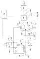
- FIGS 1 a and 1 b show a schematic illustration of a prior art trailer service braking system 10 comprising a service actuator 12 which is connected to a delivery port 14a of braking control valve assembly, which in this embodiment of the invention is an anti-lock braking system (ABS) modulator valve assembly 14.
- the modulator valve assembly 14 has an exhaust port 14c which is connected to a low pressure region (typically the atmosphere), and a control port 14d.
- the control port 14d is connected to the outlet 22a of a pilot operated emergency apply valve 22.
- the emergency apply valve 22 has a first inlet 22b, a second inlet 22c, and a control port 22d, the first inlet 22b being connected to a control line 24, the second inlet 22c and the control port 22d being connected to a supply line 16.
- the emergency apply valve 22 is a two position valve which is movable between a first position (illustrated in Figure 1 a) in which the first inlet 22b is connected to the outlet 22a whilst the second inlet 22c is closed, and a second position (illustrated in Figure 1 b) in which the first inlet 22b is closed whilst the second inlet 22c is connected to the outlet 22a.
- the emergency apply valve 22 is provided with resilient biasing means (a spring) which urges it to the second position, and will move to the first position when the fluid pressure at the control port 22d is sufficient to overcome the biasing force of the spring.
- the supply line 16 is, in use, connected to a source of pressurised fluid (typically compressed air).
- a source of pressurised fluid typically compressed air
- the supply line 16 extends to a pneumatic or hydraulic supply connector 18 which is adapted, in use, to be connected to the source of pressurised fluid via a corresponding connector on the tractor.
- a non-return (or one-way) valve 20 is provided in the supply line 16, the non-return valve 20 permitting flow of fluid along the supply line 16 to the emergency apply valve whilst substantially preventing flow of pressurised fluid in the opposite direction from the emergency apply valve to the supply connector 18.
- the control port 22d of the emergency apply valve 22 is connected to the supply line 16 upstream of the non-return valve 20, so that the non-return valve 20 is located in the supply line between the emergency apply valve 22 and the connection to the control port 22d.
- the control line 24 is connected to a source of a pressurised fluid braking demand signal.
- the pressurised fluid braking demand signal typically originates on the tractor and is typically generated by a driver operating a foot pedal provided on the tractor.
- the control line 24 extends to a pneumatic or hydraulic control connector 26 which is adapted, in use, to be connected to the source of pressurised fluid braking demand signal via a corresponding connector on the tractor.
- a pressure transducer 28 is provided to measure the fluid pressure in the control line 24.
- the modulator valve assembly 14 is operable to move between a build position in which the delivery port 14a is connected to a source of pressurised fluid whilst the exhaust port 14c is closed, a hold position in which the delivery port 14a and the exhaust port are 14c are closed, and an exhaust position in which the delivery port 14a is connected to the exhaust port 14c.
- the modulator valve assembly 14 may be configured such that, when the valve is in the build configuration, the control port 14d is connected to the delivery port 14a. In this case, the control pressure provides the source of pressurised fluid transmitted to the brake actuator 12a.
- the modulator valve assembly 14 is typically, however, a relay valve in which the control port 14d is connected to a control chamber, the delivery port 14a being connected to a separate source of pressurised fluid (reservoir 30 for example) when the modulator valve assembly 14 is in the build position.
- the modulator valve assembly is also provided with an electrically operable dump valve and hold valve.
- the modulator valve assembly 14 is configured such that, when there is no supply of electrical current to either the dump valve or the hold valve, the supply of pressurised fluid at the control port 14d causes the modulator valve assembly to move to the build position until the pressure at the delivery port 14a is balanced with the pressure at the control port 14d, at which point the modulator valve assembly 14 moves to the hold position.
- the pressure supplied to the brake actuator 12a is thus determined by the pressure at the control port 14d as required for normal service braking.
- the modulator valve assembly 14 is configured to move to the hold position when there is supply of electrical current to the hold valve but not to the dump valve, and to move to the exhaust position when there is supply of electrical current to the dump valve and to the hold valve.
- the modulator valve assembly 14 could equally be configured to adopt the exhaust position when there is supply of electrical current to the dump valve but not the hold valve.
- the braking system 10 is provided with a pressurised fluid reservoir 30 which is connected to the supply line 16 downstream of the non-return valve 20.
- the braking system 10 adopts the configuration shown in Figure 1 a.
- Fluid pressure in the supply line 16 causes the emergency apply valve 22 to move against the biasing force of its spring into its first position.
- any fluid pressure braking demand signal generated by driver demand for braking is flows via the emergency apply valve 22 and to the control inlet 14d of the modulator valve assembly 14. Pressurised fluid is thus supplied to the actuator 12, which causes it to move to the brake apply position. A braking force is thus applied to the vehicle.
- the braking system 10 is also provided with an electronic braking control unit (ECU) 32 which controls operation of the at least one electrically operable valve in the modulator valve assembly 14.
- ECU electronic braking control unit
- At least one wheel speed sensor (not shown) is provided to monitor the speed of a wheel of the trailer, and conventional anti-lock braking algorithms are employed to detect locking of the wheel. If wheel lock is detected, the braking ECU 32 controls the electrically operable valves in the modulator valve assembly 14 so that it moves to either the hold position or the exhaust position in accordance with standard ABS control procedures.
- a stability control intervention could be the automatic reduction in the driving torque from the engine, or automatic application of the vehicle brakes.
- EBS electronic braking system
- EP0586203 discloses a pneumatic braking system for a vehicle in which electrically/electronically initiated braking is achieved using an arrangement of an electrically operable valve and shuttle valve which are placed between the emergency apply valve and the modulator valve assembly.
- a trailer/semi-trailer vehicle braking system comprising a brake actuator which is operable to adopt a brake apply position in which the actuator may apply a braking force to a vehicle wheel and a brake release position in which the actuator may release any braking force applied to a vehicle wheel, supply of pressurised fluid to the actuator causing the brake actuator to move to the brake apply position and release of pressurised fluid from the actuator causing the brake actuator to move to the brake release position, a braking control valve assembly having a delivery port which is connected to the actuator by means of which pressurised fluid may be supplied to the actuator, a supply line which is connected to a source of pressurised fluid, and a braking control line which is adapted in use to be connected to a source of a fluid pressure braking demand signal, the system further including an emergency apply valve having a control port which is connected to the supply line by means of a further control line and which is movable in response to fluid pressure at the control port between a first position
- the brake apply valve is provided with an electrically operable valve actuator which moves the valve from the first position to the second position, when there is supply of sufficient electrical power to the valve actuator.
- the brake apply valve may be provided with a resilient biasing element which moves the valve from the second position to the first position when there is no electrical power supplied to the valve actuator.
- the emergency apply valve is provided with a resilient biasing element which moves the valve to its second position when the fluid pressure at its control port is below a predetermined level.
- the emergency apply valve may be configured to move to its first position when the fluid pressure at its control port exceeds a predetermined level.
- system further comprises a pressurised fluid reservoir which is connected to the supply line.
- a one-way valve may be provided in the supply line between the emergency apply valve and the connection between the supply line and the further control line, the one-way valve permitting flow of fluid along the supply line towards the emergency apply valve whilst substantially preventing flow of fluid along the supply line in the opposite direction.
- the pressurised fluid reservoir is connected to the supply line between the one-way valve and the emergency apply valve.
- the braking control valve assembly may be an ABS modulator valve assembly.
- the braking control valve assembly further includes an exhaust port which connected to a low pressure region and is electrically operable to move between a build position in which its delivery port is connected to a source of pressurised fluid whilst its exhaust port is closed, a hold position in which flow of fluid through the delivery port and exhaust port is substantially prevented, and an exhaust position in which the delivery port is connected to the exhaust port.
- supply of electrical power of the braking control valve assembly is required to move the assembly to either the exhaust or hold positions.
- the system may further comprise an electronic braking controller which controls the supply of electrical power to the braking control valve assembly. In this case, preferably the electronic braking controller also controls the supply of electrical power to the brake apply valve.
- a vehicle stability control system including a braking system according to the first aspect of the invention and a sensor for determining if the stability of the vehicle is compromised.
- a third aspect of the invention we provide a method of operating a vehicle stability control system according to the second aspect of the invention wherein, if it is determined that the stability of the vehicle is compromised, sufficient electrical power is supplied to the brake apply valve so that the brake apply valve moves to its second position, and the service brake actuator acts to apply a braking force to the vehicle.
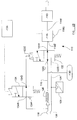
- a trailer braking system 110 which has a service brake actuator 112, a modulator valve assembly 114, a supply line 116, a supply connector 118, a non-return valve 120, an emergency apply valve 122, a control line 124, a control connector 126, a pressure transducer 128, a trailer pressurised fluid reservoir 130, and a braking ECU 132 all arranged just as described above in relation to the prior art system 10 shown in Figures 1 a and 1 b.
- valve 134 The difference between the prior art system 10 and system 110 shown in Figures 2a , 2b , 2c is that there is an electrically operated brake apply valve 134 provided in the line between the control port 122d of the emergency apply valve 122 and the supply line 116.
- This valve 134 has an inlet 134a which is connected to the supply line 116, an outlet 134b which is connected to the control port 122d of the emergency apply valve 122, and an exhaust port 134c which vents to a low pressure region, typically the atmosphere.
- the brake apply valve 134 is movable between a first position (illustrated in Figures 2a and 2b ) in which the inlet 134a is connected to the outlet 134b, and a second position (illustrated in Figure 2c ) in which the inlet 134a is closed and the outlet 134b is connected to the exhaust port 134c.
- the brake apply valve 134 is also provided with a resilient biasing element (a spring) which urges the valve 134 into the first position, and an electrically operable actuator (for example a solenoid or piezoelectric element) which, when supplied with electrical power, causes the valve to move against the biasing force of the spring into the second position.
- the brake apply valve 134a is electrically connected to the braking ECU 132 so that the braking ECU 132 controls the supply of electrical power to the electrical actuator of the brake apply valve 116.
- the braking system 110 may, however, be operated to apply a braking force to the trailer when the supply line 116 is connected to a supply of pressurised fluid and when there is no driver demand for braking-for example if a stability control system has determined that the stability of the vehicle is compromised and braking of the vehicle is required to improve the stability of the vehicle.
- electrical power is supplied to the brake apply valve 134. This causes it to move against the biasing force of its spring into its second position as illustrated in Figure 2c .
- the control port 122d of the emergency apply valve 122 is thus vented to atmosphere, and so the emergency apply valve 122 moves under the influence of its spring to its second position.
- the control port 114d of the modulator valve assembly 114 is thus connected to the trailer reservoir 130, and pressurised fluid is supplied to the brake actuator 112 which applies a braking force to the trailer just as occurs under emergency braking conditions.
- the braking ECU 132 may be operated, if desired, to provide conventional anti-lock protection during the braking event.
- the brake apply valve 134 When braking is no longer required, the supply of electrical power to the brake apply valve 134 is ceased, and the brake apply valve 134 and emergency apply valve 122 move back under the influence of their springs to their first positions as illustrated in Figure 2a .
- the ECU 132 is programmed to operate the electrically operable valve or valve of the modulator valve assembly 114 to move the modulator valve assembly 114 to the exhaust position, and thus to vent fluid pressure from the brake actuator 112. The brake is then released.
- the addition of the brake apply valve 134 thus means that the prior art ABS trailer braking system can be used in conjunction with a stability control system without the need to provide full electronic braking system (EBS) control.
- EBS electronic braking system
- the term "line” covers any type of conduit for pressurised fluid including a passage or bore through a housing, a hose, pipe or tube. It should also be appreciated that, whilst in this example, the modulator valve assembly 114 may be connected to more than one brake actuator.
Landscapes
- Engineering & Computer Science (AREA)
- Transportation (AREA)
- Mechanical Engineering (AREA)
- Regulating Braking Force (AREA)
Description
- The present invention relates to a vehicle braking system, particularly, to a braking system for a trailer or semi-trailer of a road vehicle comprising a tractor and trailer combination.
- Large commercial trailers are typically fitted with two types of brake actuator-a service actuator in which air pressure on a piston or diaphragm pushes a rod which applies mechanical turning force to the input shaft of the brake, and a service/spring actuator which includes, in addition to a service actuator, a spring actuator comprising an internal coil spring which acts on the pushrod, which can be compressed when a second chamber is pressurised. The brakes can be applied therefore by either increasing pressure supplied to the service actuator as normal, and/or by a reducing the pressure supplied to the spring actuator. A common configuration, for example, is a semi-trailer with three axles, the front of which has service actuators and the middle and rear of which has service/spring actuators. Other combinations are possible, however.
- In the normal driving condition the spring actuators are pressurised from the compressed air supply line (or trailer reservoir) to hold them off. Graduated braking in response to driver demand for braking is effected via the service actuators. The present invention relates to a system for actuating the service brake of a trailer or semi-trailer.
-
Figures 1 a and 1 b show a schematic illustration of a prior art trailerservice braking system 10 comprising aservice actuator 12 which is connected to adelivery port 14a of braking control valve assembly, which in this embodiment of the invention is an anti-lock braking system (ABS)modulator valve assembly 14. In addition to thedelivery port 14a, themodulator valve assembly 14 has an exhaust port 14c which is connected to a low pressure region (typically the atmosphere), and acontrol port 14d. - The
control port 14d is connected to theoutlet 22a of a pilot operated emergency applyvalve 22. In addition to theoutlet 22a, the emergency applyvalve 22 has afirst inlet 22b, a second inlet 22c, and acontrol port 22d, thefirst inlet 22b being connected to acontrol line 24, the second inlet 22c and thecontrol port 22d being connected to asupply line 16. The emergency applyvalve 22 is a two position valve which is movable between a first position (illustrated inFigure 1 a) in which thefirst inlet 22b is connected to theoutlet 22a whilst the second inlet 22c is closed, and a second position (illustrated inFigure 1 b) in which thefirst inlet 22b is closed whilst the second inlet 22c is connected to theoutlet 22a. The emergency applyvalve 22 is provided with resilient biasing means (a spring) which urges it to the second position, and will move to the first position when the fluid pressure at thecontrol port 22d is sufficient to overcome the biasing force of the spring. - The
supply line 16 is, in use, connected to a source of pressurised fluid (typically compressed air). When the trailer is pulled by a towing vehicle (tractor) the source of pressurised fluid is typically provided on the tractor, so thesupply line 16 extends to a pneumatic orhydraulic supply connector 18 which is adapted, in use, to be connected to the source of pressurised fluid via a corresponding connector on the tractor. A non-return (or one-way)valve 20 is provided in thesupply line 16, thenon-return valve 20 permitting flow of fluid along thesupply line 16 to the emergency apply valve whilst substantially preventing flow of pressurised fluid in the opposite direction from the emergency apply valve to thesupply connector 18. - The
control port 22d of the emergency applyvalve 22 is connected to thesupply line 16 upstream of thenon-return valve 20, so that thenon-return valve 20 is located in the supply line between the emergency applyvalve 22 and the connection to thecontrol port 22d. - The
control line 24 is connected to a source of a pressurised fluid braking demand signal. When the trailer is pulled by a towing vehicle (tractor) the pressurised fluid braking demand signal typically originates on the tractor and is typically generated by a driver operating a foot pedal provided on the tractor. As such, thecontrol line 24 extends to a pneumatic orhydraulic control connector 26 which is adapted, in use, to be connected to the source of pressurised fluid braking demand signal via a corresponding connector on the tractor. Typically apressure transducer 28 is provided to measure the fluid pressure in thecontrol line 24. - The
modulator valve assembly 14 is operable to move between a build position in which thedelivery port 14a is connected to a source of pressurised fluid whilst the exhaust port 14c is closed, a hold position in which thedelivery port 14a and the exhaust port are 14c are closed, and an exhaust position in which thedelivery port 14a is connected to the exhaust port 14c. Themodulator valve assembly 14 may be configured such that, when the valve is in the build configuration, thecontrol port 14d is connected to thedelivery port 14a. In this case, the control pressure provides the source of pressurised fluid transmitted to the brake actuator 12a. Themodulator valve assembly 14 is typically, however, a relay valve in which thecontrol port 14d is connected to a control chamber, thedelivery port 14a being connected to a separate source of pressurised fluid (reservoir 30 for example) when themodulator valve assembly 14 is in the build position. - The modulator valve assembly is also provided with an electrically operable dump valve and hold valve. The
modulator valve assembly 14 is configured such that, when there is no supply of electrical current to either the dump valve or the hold valve, the supply of pressurised fluid at thecontrol port 14d causes the modulator valve assembly to move to the build position until the pressure at thedelivery port 14a is balanced with the pressure at thecontrol port 14d, at which point themodulator valve assembly 14 moves to the hold position. The pressure supplied to the brake actuator 12a is thus determined by the pressure at thecontrol port 14d as required for normal service braking. - Typically, the
modulator valve assembly 14 is configured to move to the hold position when there is supply of electrical current to the hold valve but not to the dump valve, and to move to the exhaust position when there is supply of electrical current to the dump valve and to the hold valve. Themodulator valve assembly 14 could equally be configured to adopt the exhaust position when there is supply of electrical current to the dump valve but not the hold valve. - Various configurations of these type of modulator valve assembly for in use in ABS braking systems, and are well known to persons of skill in the art.
- It will be appreciated that when the
modulator valve assembly 14 is in the build position, and when there is a fluid pressure at thecontrol port 14d, this pressurised fluid (or, where the modulator valve assembly is a relay valve, fluid from the alternative source of pressurised fluid) is transmitted to theservice actuator 12, or more precisely a working chamber in theservice actuator 12, and theservice actuator 12 is configured to respond to this by actuating a brake to apply a braking force to the trailer. Similarly, when themodulator valve assembly 14 is in the exhaust position, pressurised fluid is exhausted from theservice actuator 12, or more precisely a working chamber in theservice actuator 12, and theservice actuator 12 is configured to respond to this by releasing the braking force. When themodulator valve assembly 14 is in the hold position, fluid pressure in theservice actuator 12 is maintained, and so any braking force applied by theactuator 12 is held at a substantially constant level. - Finally, the
braking system 10 is provided with apressurised fluid reservoir 30 which is connected to thesupply line 16 downstream of thenon-return valve 20. - During normal use, the
braking system 10 adopts the configuration shown inFigure 1 a. Fluid pressure in thesupply line 16 causes the emergency applyvalve 22 to move against the biasing force of its spring into its first position. Thus, any fluid pressure braking demand signal generated by driver demand for braking is flows via the emergency applyvalve 22 and to thecontrol inlet 14d of themodulator valve assembly 14. Pressurised fluid is thus supplied to theactuator 12, which causes it to move to the brake apply position. A braking force is thus applied to the vehicle. - The
braking system 10 is also provided with an electronic braking control unit (ECU) 32 which controls operation of the at least one electrically operable valve in themodulator valve assembly 14. At least one wheel speed sensor (not shown) is provided to monitor the speed of a wheel of the trailer, and conventional anti-lock braking algorithms are employed to detect locking of the wheel. If wheel lock is detected, thebraking ECU 32 controls the electrically operable valves in themodulator valve assembly 14 so that it moves to either the hold position or the exhaust position in accordance with standard ABS control procedures. - If, however, the
supply connector 18 becomes disconnected from its connection to the supply of pressurised fluid, the portion of thesupply line 16 up-stream of thenon-return valve 20 is exhausted to atmosphere. The resulting loss of fluid pressure at thecontrol port 22d of the emergency applyvalve 22 causes it to move under the action of its spring to its second position as illustrated inFigure 1 b. As a result, thecontrol port 14d of themodulator valve assembly 14 is connected to the trailer pressurisedfluid reservoir 30. The pressurised fluid therefore travels to thebrake actuator 12 to apply a braking force to the trailer. In other words, thisbraking system 10 provides for automatic application of the service brake in the event that the trailer becomes disconnected from its normal supply of pressurised fluid. The braking ECU 32 operates to provide conventional ABS control in the event of wheel slip during this emergency braking. - It is also known to provide trailer vehicles with a stability control system which detects (for example using wheel speed or lateral acceleration sensors) if the stability of the vehicle is comprised, e.g. if the vehicle is cornering so fast that the vehicle is likely to roll over, and initiates a stability control intervention if it is. A stability control intervention could be the automatic reduction in the driving torque from the engine, or automatic application of the vehicle brakes. The latter kind of stability control system is typically employed in trailers equipped with an electronic braking system (EBS), as such a system already provides a means for electrically/electronically initiated braking.
-
EP0586203 discloses a pneumatic braking system for a vehicle in which electrically/electronically initiated braking is achieved using an arrangement of an electrically operable valve and shuttle valve which are placed between the emergency apply valve and the modulator valve assembly. - According to a first aspect of the invention we provide a trailer/semi-trailer vehicle braking system comprising a brake actuator which is operable to adopt a brake apply position in which the actuator may apply a braking force to a vehicle wheel and a brake release position in which the actuator may release any braking force applied to a vehicle wheel, supply of pressurised fluid to the actuator causing the brake actuator to move to the brake apply position and release of pressurised fluid from the actuator causing the brake actuator to move to the brake release position, a braking control valve assembly having a delivery port which is connected to the actuator by means of which pressurised fluid may be supplied to the actuator, a supply line which is connected to a source of pressurised fluid, and a braking control line which is adapted in use to be connected to a source of a fluid pressure braking demand signal, the system further including an emergency apply valve having a control port which is connected to the supply line by means of a further control line and which is movable in response to fluid pressure at the control port between a first position in which the braking control line is connected to a control port of the braking control valve assembly, and a second position in which the supply line is connected to the control port of the braking control valve assembly, wherein the braking system is also provided with a electrically operable brake apply valve in the further control line, the brake apply valve being movable between a first position in which fluid flow along further control line is permitted and a second position in which fluid flow along the further control line is substantially prevented and the control port of the emergency apply valve is connected to a low pressure region.
- In one embodiment of the invention, the brake apply valve is provided with an electrically operable valve actuator which moves the valve from the first position to the second position, when there is supply of sufficient electrical power to the valve actuator. In this case, the brake apply valve may be provided with a resilient biasing element which moves the valve from the second position to the first position when there is no electrical power supplied to the valve actuator.
- In one embodiment of the invention the emergency apply valve is provided with a resilient biasing element which moves the valve to its second position when the fluid pressure at its control port is below a predetermined level. In this case, the emergency apply valve may be configured to move to its first position when the fluid pressure at its control port exceeds a predetermined level.
- In one embodiment of the invention the system further comprises a pressurised fluid reservoir which is connected to the supply line.
- A one-way valve may be provided in the supply line between the emergency apply valve and the connection between the supply line and the further control line, the one-way valve permitting flow of fluid along the supply line towards the emergency apply valve whilst substantially preventing flow of fluid along the supply line in the opposite direction. In this case, the pressurised fluid reservoir is connected to the supply line between the one-way valve and the emergency apply valve.
- The braking control valve assembly may be an ABS modulator valve assembly.
- In one embodiment of the invention, the braking control valve assembly further includes an exhaust port which connected to a low pressure region and is electrically operable to move between a build position in which its delivery port is connected to a source of pressurised fluid whilst its exhaust port is closed, a hold position in which flow of fluid through the delivery port and exhaust port is substantially prevented, and an exhaust position in which the delivery port is connected to the exhaust port. In this case, preferably supply of electrical power of the braking control valve assembly is required to move the assembly to either the exhaust or hold positions. Moreover, the system may further comprise an electronic braking controller which controls the supply of electrical power to the braking control valve assembly. In this case, preferably the electronic braking controller also controls the supply of electrical power to the brake apply valve.
- According to a second aspect of the invention we provide a vehicle stability control system including a braking system according to the first aspect of the invention and a sensor for determining if the stability of the vehicle is compromised.
- According to a third aspect of the invention we provide a method of operating a vehicle stability control system according to the second aspect of the invention wherein, if it is determined that the stability of the vehicle is compromised, sufficient electrical power is supplied to the brake apply valve so that the brake apply valve moves to its second position, and the service brake actuator acts to apply a braking force to the vehicle.
- An embodiment of the invention will now be described, by way of example only, with reference to the accompanying figures of which,
-
FIGURE 2a shows a schematic illustration of a trailer braking system in accordance with the invention in the normal braking configuration, -
FIGURE 2b shows a schematic illustration of the trailer braking system in accordance with the invention in the emergency braking configuration, and -
FIGURE 2c shows a schematic illustration of the trailer braking system in accordance with the invention in the electronic braking configuration. - Referring now to
Figures 2a ,2b ,2c , there is shown atrailer braking system 110 which has aservice brake actuator 112, amodulator valve assembly 114, asupply line 116, asupply connector 118, anon-return valve 120, an emergency applyvalve 122, acontrol line 124, acontrol connector 126, apressure transducer 128, a trailer pressurisedfluid reservoir 130, and abraking ECU 132 all arranged just as described above in relation to theprior art system 10 shown inFigures 1 a and 1 b. The difference between theprior art system 10 andsystem 110 shown inFigures 2a ,2b ,2c is that there is an electrically operated brake applyvalve 134 provided in the line between thecontrol port 122d of the emergency applyvalve 122 and thesupply line 116. Thisvalve 134 has aninlet 134a which is connected to thesupply line 116, anoutlet 134b which is connected to thecontrol port 122d of the emergency applyvalve 122, and an exhaust port 134c which vents to a low pressure region, typically the atmosphere. The brake applyvalve 134 is movable between a first position (illustrated inFigures 2a and2b ) in which theinlet 134a is connected to theoutlet 134b, and a second position (illustrated inFigure 2c ) in which theinlet 134a is closed and theoutlet 134b is connected to the exhaust port 134c. The brake applyvalve 134 is also provided with a resilient biasing element (a spring) which urges thevalve 134 into the first position, and an electrically operable actuator (for example a solenoid or piezoelectric element) which, when supplied with electrical power, causes the valve to move against the biasing force of the spring into the second position. Advantageously, the brake applyvalve 134a is electrically connected to thebraking ECU 132 so that thebraking ECU 132 controls the supply of electrical power to the electrical actuator of the brake applyvalve 116. - During normal use, no electrical power is supplied to the brake apply
valve 134, and thebraking system 110 operates in the same way as the priorart braking system 10 described in relation toFigure 1 a above. This is illustrated inFigure 2a . Similarly, if thesupply line 116 loses its connection to a supply of pressurised fluid, thebraking system 110 operates in the same way as the priorart braking system 10 as described in relation toFigure 1 b above. This is illustrated inFigure 2b . - The
braking system 110 according to the invention may, however, be operated to apply a braking force to the trailer when thesupply line 116 is connected to a supply of pressurised fluid and when there is no driver demand for braking-for example if a stability control system has determined that the stability of the vehicle is compromised and braking of the vehicle is required to improve the stability of the vehicle. To achieve this, electrical power is supplied to the brake applyvalve 134. This causes it to move against the biasing force of its spring into its second position as illustrated inFigure 2c . Thecontrol port 122d of the emergency applyvalve 122 is thus vented to atmosphere, and so the emergency applyvalve 122 moves under the influence of its spring to its second position. Thecontrol port 114d of themodulator valve assembly 114 is thus connected to thetrailer reservoir 130, and pressurised fluid is supplied to thebrake actuator 112 which applies a braking force to the trailer just as occurs under emergency braking conditions. Again, thebraking ECU 132 may be operated, if desired, to provide conventional anti-lock protection during the braking event. - When braking is no longer required, the supply of electrical power to the brake apply
valve 134 is ceased, and the brake applyvalve 134 and emergency applyvalve 122 move back under the influence of their springs to their first positions as illustrated inFigure 2a . TheECU 132 is programmed to operate the electrically operable valve or valve of themodulator valve assembly 114 to move themodulator valve assembly 114 to the exhaust position, and thus to vent fluid pressure from thebrake actuator 112. The brake is then released. The addition of the brake applyvalve 134 thus means that the prior art ABS trailer braking system can be used in conjunction with a stability control system without the need to provide full electronic braking system (EBS) control. When used in this specification and claims, the term "line" covers any type of conduit for pressurised fluid including a passage or bore through a housing, a hose, pipe or tube. It should also be appreciated that, whilst in this example, themodulator valve assembly 114 may be connected to more than one brake actuator.
Claims (15)
- A trailer/semi-trailer vehicle (110) braking system comprising a brake actuator (112) which is operable to adopt a brake apply position in which the actuator (112) may apply a braking force to a vehicle wheel and a brake release position in which the actuator (112) may release any braking force applied to a vehicle wheel, supply of pressurised fluid to the actuator (112) causing the actuator (112) to move to the brake apply position and release of pressurised fluid from the actuator (112) causing the actuator (112) to move to the brake release position, a braking control valve assembly (114) having a delivery port (114a) which is connected to the actuator (112) by means of which pressurised fluid may be supplied to the actuator (112), a supply line (116) which is connected to a source of pressurised fluid, and a braking control line (124) which is adapted in use to be connected to a source of a fluid pressure braking demand signal, the system further including an emergency apply valve (122) having a control port (122d) which is connected to the supply line (116) by means of a further control line and which is movable in response to fluid pressure at the control port (122d) between a first position in which the braking control line (124) is connected to a control port (114d) of the braking control valve assembly (114), and a second position in which the supply line (116) is connected to the control port (114d) of the braking control valve assembly (114), wherein the braking system (110) is also provided with an electrically operable brake apply valve (134) in the further control line, the brake apply valve (134) being movable between a first position in which fluid flow along further control line is permitted and a second position in which fluid flow along the further control line is substantially prevented and the control port (122d) of the emergency apply valve (122) is connected to a low pressure region.
- A braking system (110) according to claim 1 wherein the brake apply valve (134) is provided with an electrically operable valve actuator which moves the brake apply valve (134) from the first position to the second position, when there is supply of sufficient electrical power to the valve actuator.
- A braking system (110) according to claim 2 wherein the brake apply valve (134) is provided with a resilient biasing element which moves the brake apply valve (134) from the second position to the first position when there is no electrical power supplied to the valve actuator.
- A braking system (110) according to any preceding claim wherein the emergency apply valve (122) is provided with a resilient biasing element which moves the emergency apply valve (122) to its second position when the fluid pressure at its control port (122d) is below a predetermined level.
- A braking system (110) according to claim 4 wherein the emergency apply valve (122) is configured to move to its first position when the fluid pressure at its control port (122d) exceeds a predetermined level.
- A braking system (110) according to any preceding claim wherein the system further comprises a pressurised fluid reservoir (130) which is connected to the supply line (116).
- A braking system (110) according to any preceding claim wherein a one-way valve (120) is provided in the supply line (116) between the emergency apply valve (122) and the connection between the supply line (116) and the further control line, the one-way valve (120) permitting flow of fluid along the supply line (116) towards the emergency apply valve (122) whilst substantially preventing flow of fluid along the supply line (116) in the opposite direction.
- A braking system (110) according to claim 6 and 7 wherein the pressurised fluid reservoir (130) is connected to the supply line (116) between the one-way valve (120) and the emergency apply valve (122).
- A braking system (110) according to any preceding claim wherein the braking control valve assembly (114) is an ABS modulator valve assembly.
- A braking system (110) according to claim 9 wherein the braking control valve assembly (114) further includes an exhaust port (114c) which is connected to a low pressure region and is electrically operable to move between a build position in which its delivery port (114a) is connected to a source of pressurised fluid whilst its exhaust port (114c) is closed, a hold position in which flow of fluid through the delivery port (114a) and exhaust port (114c) is substantially prevented, and an exhaust position in which the delivery port (114c) is connected to the exhaust port (114c).
- A braking system (110) according to claim 10 wherein supply of electrical power of the braking control valve assembly (114) is required to move the assembly (114) to either the exhaust or hold positions.
- A braking system (110) according to claim 10 wherein the braking system (110) further comprises an electronic braking controller (132) which controls the supply of electrical power to the braking control valve assembly (114).
- A braking system (110) according to claim 12 wherein the electronic braking controller (132) also controls the supply of electrical power to the brake apply valve (134).
- A vehicle stability control system including a braking system (110) according to any preceding claim and a sensor for determining if the stability of the vehicle is compromised.
- A method of operating a vehicle stability control system according to claim 14 wherein, if it is determined that the stability of the vehicle is compromised, sufficient electrical power is supplied to the brake apply valve (134) so that the brake apply valve (134) moves to its second position, and the brake actuator (112) acts to apply a braking force to the vehicle.
Priority Applications (1)
| Application Number | Priority Date | Filing Date | Title |
|---|---|---|---|
| PL12707894T PL2750945T3 (en) | 2011-06-10 | 2012-02-22 | Vehicle braking system |
Applications Claiming Priority (2)
| Application Number | Priority Date | Filing Date | Title |
|---|---|---|---|
| GB1109730.0A GB2491639A (en) | 2011-06-10 | 2011-06-10 | Vehicle Braking System |
| PCT/GB2012/050401 WO2012168688A1 (en) | 2011-06-10 | 2012-02-22 | Vehicle braking system |
Publications (2)
| Publication Number | Publication Date |
|---|---|
| EP2750945A1 EP2750945A1 (en) | 2014-07-09 |
| EP2750945B1 true EP2750945B1 (en) | 2015-11-04 |
Family
ID=44357512
Family Applications (1)
| Application Number | Title | Priority Date | Filing Date |
|---|---|---|---|
| EP12707894.7A Active EP2750945B1 (en) | 2011-06-10 | 2012-02-22 | Vehicle braking system |
Country Status (8)
| Country | Link |
|---|---|
| US (1) | US9290166B2 (en) |
| EP (1) | EP2750945B1 (en) |
| CN (1) | CN103608225B (en) |
| BR (1) | BR112013030514B1 (en) |
| GB (1) | GB2491639A (en) |
| HU (1) | HUE025888T2 (en) |
| PL (1) | PL2750945T3 (en) |
| WO (1) | WO2012168688A1 (en) |
Families Citing this family (14)
| Publication number | Priority date | Publication date | Assignee | Title |
|---|---|---|---|---|
| EP2881595B1 (en) * | 2013-12-03 | 2018-08-22 | Ansaldo Energia IP UK Limited | Device for emergency operation of actuators |
| US10549742B2 (en) * | 2015-09-23 | 2020-02-04 | Agco International Gmbh | Vehicle trailer brake system and method |
| US10093296B2 (en) * | 2017-01-25 | 2018-10-09 | Goodrich Corporation | Electrically activated park and emergency valve with on-valve manual actuation feature |
| EP3379222B1 (en) | 2017-03-22 | 2020-12-30 | Methode Electronics Malta Ltd. | Magnetoelastic based sensor assembly |
| US11491832B2 (en) | 2018-02-27 | 2022-11-08 | Methode Electronics, Inc. | Towing systems and methods using magnetic field sensing |
| US11084342B2 (en) | 2018-02-27 | 2021-08-10 | Methode Electronics, Inc. | Towing systems and methods using magnetic field sensing |
| US11221262B2 (en) | 2018-02-27 | 2022-01-11 | Methode Electronics, Inc. | Towing systems and methods using magnetic field sensing |
| WO2019168565A1 (en) | 2018-02-27 | 2019-09-06 | Methode Electronics,Inc. | Towing systems and methods using magnetic field sensing |
| US11014417B2 (en) | 2018-02-27 | 2021-05-25 | Methode Electronics, Inc. | Towing systems and methods using magnetic field sensing |
| US11135882B2 (en) | 2018-02-27 | 2021-10-05 | Methode Electronics, Inc. | Towing systems and methods using magnetic field sensing |
| GB2575696B (en) * | 2018-07-20 | 2022-07-13 | Haldex Brake Prod Ab | Vehicle braking system |
| ES2916401T3 (en) * | 2019-11-18 | 2022-06-30 | Knorr Bremse Systeme Fuer Nutzfahrzeuge Gmbh | Brake system for an air supply and control module of motor vehicles and trailers |
| CN113479175B (en) * | 2021-08-23 | 2022-07-12 | 广州朗晴电动车有限公司 | But braking system device of self-propelled fire control trailer |
| US12060052B2 (en) * | 2021-09-10 | 2024-08-13 | Goodrich Corporation | Valve assembly for brake control system |
Family Cites Families (10)
| Publication number | Priority date | Publication date | Assignee | Title |
|---|---|---|---|---|
| GB8506978D0 (en) * | 1985-03-18 | 1985-04-24 | Lucas Ind Plc | Vehicle anti-skid air braking systems |
| DE3936726A1 (en) * | 1989-11-04 | 1991-05-08 | Wabco Westinghouse Fahrzeug | METHOD FOR BRAKING A VEHICLE TRAIN PRESSURIZED BRAKES |
| DE4130848C1 (en) * | 1991-09-17 | 1993-03-18 | Mercedes-Benz Aktiengesellschaft, 7000 Stuttgart, De | |
| DE69307057T2 (en) | 1992-09-03 | 1997-07-17 | Grau Ltd | Braking systems |
| DE19637484A1 (en) * | 1996-09-14 | 1998-03-19 | Wabco Gmbh | Two-line trailer brake system |
| US6741922B2 (en) * | 2002-05-30 | 2004-05-25 | Bendix Commercial Vehicle Systems Llc | Antilock braking system based roll over prevention |
| US7020551B2 (en) * | 2003-12-23 | 2006-03-28 | Bendix Commercial Vehicle Systems Llc | Roll stability control system |
| DE102005054089C5 (en) * | 2005-11-12 | 2012-04-12 | Haldex Brake Products Gmbh | Control unit for a compressed air brake system of a motor vehicle |
| US7971942B2 (en) * | 2006-09-19 | 2011-07-05 | Wabco Gmbh | Trailer brake system |
| DE102007047691A1 (en) * | 2007-10-05 | 2009-04-09 | Wabco Gmbh | Electro-pneumatic parking brake modulator for controlling a parking brake function of brakes of a trailer in a vehicle train |
-
2011
- 2011-06-10 GB GB1109730.0A patent/GB2491639A/en not_active Withdrawn
-
2012
- 2012-02-22 EP EP12707894.7A patent/EP2750945B1/en active Active
- 2012-02-22 HU HUE12707894A patent/HUE025888T2/en unknown
- 2012-02-22 BR BR112013030514-2A patent/BR112013030514B1/en active IP Right Grant
- 2012-02-22 CN CN201280028275.5A patent/CN103608225B/en not_active Expired - Fee Related
- 2012-02-22 PL PL12707894T patent/PL2750945T3/en unknown
- 2012-02-22 US US14/125,262 patent/US9290166B2/en active Active
- 2012-02-22 WO PCT/GB2012/050401 patent/WO2012168688A1/en active Application Filing
Also Published As
| Publication number | Publication date |
|---|---|
| GB201109730D0 (en) | 2011-07-27 |
| US9290166B2 (en) | 2016-03-22 |
| CN103608225B (en) | 2017-07-25 |
| PL2750945T3 (en) | 2016-04-29 |
| GB2491639A (en) | 2012-12-12 |
| BR112013030514A2 (en) | 2017-06-20 |
| WO2012168688A1 (en) | 2012-12-13 |
| EP2750945A1 (en) | 2014-07-09 |
| HUE025888T2 (en) | 2016-05-30 |
| BR112013030514B1 (en) | 2021-04-20 |
| US20140183935A1 (en) | 2014-07-03 |
| CN103608225A (en) | 2014-02-26 |
Similar Documents
| Publication | Publication Date | Title |
|---|---|---|
| EP2750945B1 (en) | Vehicle braking system | |
| EP2750949B1 (en) | Vehicle braking system | |
| EP3150450B1 (en) | Vehicle braking system | |
| US8651588B2 (en) | Electro-pneumatic brake control device | |
| US9446746B2 (en) | Method of vehicle stability control | |
| US11634109B2 (en) | Method for decelerating a vehicle, in particular a commercial vehicle, electro-pneumatic brake system for decelerating a vehicle, and vehicle having an electro-pneumatic brake system | |
| EP2067675B1 (en) | Brake control circuit | |
| US7658453B2 (en) | Service brake relay with integrated quick release valve | |
| CN108137022B (en) | Electropneumatic device for controlling the braking of a railway vehicle | |
| EP0837806B1 (en) | Brake system for a trailer vehicle and a valve for use therein | |
| EP3655295B1 (en) | Utilizing a park brake system to improve the deceleration of a vehicle in the event of failure of the service brake system | |
| EP3275747B1 (en) | Pneumatic trailer brake circuit with breakaway detection and method thereof | |
| GB2543037A (en) | Vehicle braking system and valve assembly for controlling a vehicle braking system | |
| GB2490925A (en) | Vehicle braking system | |
| CN112088115B (en) | Redundant brake unit for a brake system and system using the same | |
| KR102502927B1 (en) | Method for adjusting brake pressures of a vehicle via control of a pressure control valve, brake system for carrying out the method and motor vehicle | |
| GB2509806B (en) | Electrohydraulic antilock brake system with isolation valve | |
| US8777332B2 (en) | Braking control system | |
| US20180148025A1 (en) | Electronically slip-controllable braking system | |
| CN117597279A (en) | Electro-pneumatic valve installation with self-retaining safety valve |
Legal Events
| Date | Code | Title | Description |
|---|---|---|---|
| PUAI | Public reference made under article 153(3) epc to a published international application that has entered the european phase |
Free format text: ORIGINAL CODE: 0009012 |
|
| 17P | Request for examination filed |
Effective date: 20131127 |
|
| AK | Designated contracting states |
Kind code of ref document: A1 Designated state(s): AL AT BE BG CH CY CZ DE DK EE ES FI FR GB GR HR HU IE IS IT LI LT LU LV MC MK MT NL NO PL PT RO RS SE SI SK SM TR |
|
| DAX | Request for extension of the european patent (deleted) | ||
| GRAP | Despatch of communication of intention to grant a patent |
Free format text: ORIGINAL CODE: EPIDOSNIGR1 |
|
| INTG | Intention to grant announced |
Effective date: 20150717 |
|
| GRAS | Grant fee paid |
Free format text: ORIGINAL CODE: EPIDOSNIGR3 |
|
| GRAA | (expected) grant |
Free format text: ORIGINAL CODE: 0009210 |
|
| AK | Designated contracting states |
Kind code of ref document: B1 Designated state(s): AL AT BE BG CH CY CZ DE DK EE ES FI FR GB GR HR HU IE IS IT LI LT LU LV MC MK MT NL NO PL PT RO RS SE SI SK SM TR |
|
| REG | Reference to a national code |
Ref country code: GB Ref legal event code: FG4D |
|
| REG | Reference to a national code |
Ref country code: CH Ref legal event code: EP |
|
| REG | Reference to a national code |
Ref country code: AT Ref legal event code: REF Ref document number: 758959 Country of ref document: AT Kind code of ref document: T Effective date: 20151115 |
|
| REG | Reference to a national code |
Ref country code: IE Ref legal event code: FG4D |
|
| REG | Reference to a national code |
Ref country code: DE Ref legal event code: R096 Ref document number: 602012012134 Country of ref document: DE |
|
| REG | Reference to a national code |
Ref country code: FR Ref legal event code: PLFP Year of fee payment: 5 |
|
| REG | Reference to a national code |
Ref country code: NL Ref legal event code: MP Effective date: 20151104 |
|
| REG | Reference to a national code |
Ref country code: LT Ref legal event code: MG4D |
|
| REG | Reference to a national code |
Ref country code: AT Ref legal event code: MK05 Ref document number: 758959 Country of ref document: AT Kind code of ref document: T Effective date: 20151104 |
|
| PG25 | Lapsed in a contracting state [announced via postgrant information from national office to epo] |
Ref country code: HR Free format text: LAPSE BECAUSE OF FAILURE TO SUBMIT A TRANSLATION OF THE DESCRIPTION OR TO PAY THE FEE WITHIN THE PRESCRIBED TIME-LIMIT Effective date: 20151104 Ref country code: IT Free format text: LAPSE BECAUSE OF FAILURE TO SUBMIT A TRANSLATION OF THE DESCRIPTION OR TO PAY THE FEE WITHIN THE PRESCRIBED TIME-LIMIT Effective date: 20151104 Ref country code: IS Free format text: LAPSE BECAUSE OF FAILURE TO SUBMIT A TRANSLATION OF THE DESCRIPTION OR TO PAY THE FEE WITHIN THE PRESCRIBED TIME-LIMIT Effective date: 20160304 Ref country code: NO Free format text: LAPSE BECAUSE OF FAILURE TO SUBMIT A TRANSLATION OF THE DESCRIPTION OR TO PAY THE FEE WITHIN THE PRESCRIBED TIME-LIMIT Effective date: 20160204 Ref country code: NL Free format text: LAPSE BECAUSE OF FAILURE TO SUBMIT A TRANSLATION OF THE DESCRIPTION OR TO PAY THE FEE WITHIN THE PRESCRIBED TIME-LIMIT Effective date: 20151104 Ref country code: LT Free format text: LAPSE BECAUSE OF FAILURE TO SUBMIT A TRANSLATION OF THE DESCRIPTION OR TO PAY THE FEE WITHIN THE PRESCRIBED TIME-LIMIT Effective date: 20151104 Ref country code: ES Free format text: LAPSE BECAUSE OF FAILURE TO SUBMIT A TRANSLATION OF THE DESCRIPTION OR TO PAY THE FEE WITHIN THE PRESCRIBED TIME-LIMIT Effective date: 20151104 |
|
| REG | Reference to a national code |
Ref country code: HU Ref legal event code: AG4A Ref document number: E025888 Country of ref document: HU |
|
| PG25 | Lapsed in a contracting state [announced via postgrant information from national office to epo] |
Ref country code: FI Free format text: LAPSE BECAUSE OF FAILURE TO SUBMIT A TRANSLATION OF THE DESCRIPTION OR TO PAY THE FEE WITHIN THE PRESCRIBED TIME-LIMIT Effective date: 20151104 Ref country code: SE Free format text: LAPSE BECAUSE OF FAILURE TO SUBMIT A TRANSLATION OF THE DESCRIPTION OR TO PAY THE FEE WITHIN THE PRESCRIBED TIME-LIMIT Effective date: 20151104 Ref country code: PT Free format text: LAPSE BECAUSE OF FAILURE TO SUBMIT A TRANSLATION OF THE DESCRIPTION OR TO PAY THE FEE WITHIN THE PRESCRIBED TIME-LIMIT Effective date: 20160304 Ref country code: RS Free format text: LAPSE BECAUSE OF FAILURE TO SUBMIT A TRANSLATION OF THE DESCRIPTION OR TO PAY THE FEE WITHIN THE PRESCRIBED TIME-LIMIT Effective date: 20151104 Ref country code: GR Free format text: LAPSE BECAUSE OF FAILURE TO SUBMIT A TRANSLATION OF THE DESCRIPTION OR TO PAY THE FEE WITHIN THE PRESCRIBED TIME-LIMIT Effective date: 20160205 Ref country code: BE Free format text: LAPSE BECAUSE OF NON-PAYMENT OF DUE FEES Effective date: 20160229 Ref country code: AT Free format text: LAPSE BECAUSE OF FAILURE TO SUBMIT A TRANSLATION OF THE DESCRIPTION OR TO PAY THE FEE WITHIN THE PRESCRIBED TIME-LIMIT Effective date: 20151104 Ref country code: LV Free format text: LAPSE BECAUSE OF FAILURE TO SUBMIT A TRANSLATION OF THE DESCRIPTION OR TO PAY THE FEE WITHIN THE PRESCRIBED TIME-LIMIT Effective date: 20151104 |
|
| PG25 | Lapsed in a contracting state [announced via postgrant information from national office to epo] |
Ref country code: CZ Free format text: LAPSE BECAUSE OF FAILURE TO SUBMIT A TRANSLATION OF THE DESCRIPTION OR TO PAY THE FEE WITHIN THE PRESCRIBED TIME-LIMIT Effective date: 20151104 |
|
| REG | Reference to a national code |
Ref country code: DE Ref legal event code: R097 Ref document number: 602012012134 Country of ref document: DE |
|
| PG25 | Lapsed in a contracting state [announced via postgrant information from national office to epo] |
Ref country code: EE Free format text: LAPSE BECAUSE OF FAILURE TO SUBMIT A TRANSLATION OF THE DESCRIPTION OR TO PAY THE FEE WITHIN THE PRESCRIBED TIME-LIMIT Effective date: 20151104 Ref country code: RO Free format text: LAPSE BECAUSE OF FAILURE TO SUBMIT A TRANSLATION OF THE DESCRIPTION OR TO PAY THE FEE WITHIN THE PRESCRIBED TIME-LIMIT Effective date: 20151104 Ref country code: SK Free format text: LAPSE BECAUSE OF FAILURE TO SUBMIT A TRANSLATION OF THE DESCRIPTION OR TO PAY THE FEE WITHIN THE PRESCRIBED TIME-LIMIT Effective date: 20151104 Ref country code: DK Free format text: LAPSE BECAUSE OF FAILURE TO SUBMIT A TRANSLATION OF THE DESCRIPTION OR TO PAY THE FEE WITHIN THE PRESCRIBED TIME-LIMIT Effective date: 20151104 Ref country code: SM Free format text: LAPSE BECAUSE OF FAILURE TO SUBMIT A TRANSLATION OF THE DESCRIPTION OR TO PAY THE FEE WITHIN THE PRESCRIBED TIME-LIMIT Effective date: 20151104 |
|
| PLBE | No opposition filed within time limit |
Free format text: ORIGINAL CODE: 0009261 |
|
| STAA | Information on the status of an ep patent application or granted ep patent |
Free format text: STATUS: NO OPPOSITION FILED WITHIN TIME LIMIT |
|
| PG25 | Lapsed in a contracting state [announced via postgrant information from national office to epo] |
Ref country code: LU Free format text: LAPSE BECAUSE OF FAILURE TO SUBMIT A TRANSLATION OF THE DESCRIPTION OR TO PAY THE FEE WITHIN THE PRESCRIBED TIME-LIMIT Effective date: 20160222 Ref country code: MC Free format text: LAPSE BECAUSE OF FAILURE TO SUBMIT A TRANSLATION OF THE DESCRIPTION OR TO PAY THE FEE WITHIN THE PRESCRIBED TIME-LIMIT Effective date: 20151104 |
|
| REG | Reference to a national code |
Ref country code: CH Ref legal event code: PL |
|
| 26N | No opposition filed |
Effective date: 20160805 |
|
| PG25 | Lapsed in a contracting state [announced via postgrant information from national office to epo] |
Ref country code: CH Free format text: LAPSE BECAUSE OF NON-PAYMENT OF DUE FEES Effective date: 20160229 Ref country code: LI Free format text: LAPSE BECAUSE OF NON-PAYMENT OF DUE FEES Effective date: 20160229 |
|
| PG25 | Lapsed in a contracting state [announced via postgrant information from national office to epo] |
Ref country code: SI Free format text: LAPSE BECAUSE OF FAILURE TO SUBMIT A TRANSLATION OF THE DESCRIPTION OR TO PAY THE FEE WITHIN THE PRESCRIBED TIME-LIMIT Effective date: 20151104 |
|
| REG | Reference to a national code |
Ref country code: IE Ref legal event code: MM4A |
|
| PG25 | Lapsed in a contracting state [announced via postgrant information from national office to epo] |
Ref country code: BE Free format text: LAPSE BECAUSE OF FAILURE TO SUBMIT A TRANSLATION OF THE DESCRIPTION OR TO PAY THE FEE WITHIN THE PRESCRIBED TIME-LIMIT Effective date: 20151104 |
|
| REG | Reference to a national code |
Ref country code: FR Ref legal event code: PLFP Year of fee payment: 6 |
|
| PG25 | Lapsed in a contracting state [announced via postgrant information from national office to epo] |
Ref country code: IE Free format text: LAPSE BECAUSE OF NON-PAYMENT OF DUE FEES Effective date: 20160222 |
|
| REG | Reference to a national code |
Ref country code: GB Ref legal event code: 732E Free format text: REGISTERED BETWEEN 20170324 AND 20170330 |
|
| REG | Reference to a national code |
Ref country code: HU Ref legal event code: FH1C Free format text: FORMER REPRESENTATIVE(S): SBGK SZABADALMI UEGYVIVOEI IRODA, HU Representative=s name: SBGK SZABADALMI UEGYVIVOEI IRODA, HU Ref country code: HU Ref legal event code: GB9C Owner name: HALDEX BRAKE PRODUCTS AB, SE Free format text: FORMER OWNER(S): HALDEX BRAKE PRODUCTS LIMITED, GB |
|
| PG25 | Lapsed in a contracting state [announced via postgrant information from national office to epo] |
Ref country code: MT Free format text: LAPSE BECAUSE OF FAILURE TO SUBMIT A TRANSLATION OF THE DESCRIPTION OR TO PAY THE FEE WITHIN THE PRESCRIBED TIME-LIMIT Effective date: 20151104 |
|
| REG | Reference to a national code |
Ref country code: FR Ref legal event code: PLFP Year of fee payment: 7 |
|
| REG | Reference to a national code |
Ref country code: DE Ref legal event code: R082 Ref document number: 602012012134 Country of ref document: DE Representative=s name: REHBERG HUEPPE + PARTNER PATENTANWAELTE PARTG , DE Ref country code: DE Ref legal event code: R081 Ref document number: 602012012134 Country of ref document: DE Owner name: HALDEX BRAKE PRODUCTS AKTIEBOLAG, SE Free format text: FORMER OWNER: HALDEX BRAKE PRODUCTS LTD., LINDLEY, WARWICKSHIRE, GB |
|
| REG | Reference to a national code |
Ref country code: FR Ref legal event code: TP Owner name: HALDEX BRAKE PRODUCTS AKTIEBOLAG, SE Effective date: 20180416 |
|
| PG25 | Lapsed in a contracting state [announced via postgrant information from national office to epo] |
Ref country code: CY Free format text: LAPSE BECAUSE OF FAILURE TO SUBMIT A TRANSLATION OF THE DESCRIPTION OR TO PAY THE FEE WITHIN THE PRESCRIBED TIME-LIMIT Effective date: 20151104 |
|
| PG25 | Lapsed in a contracting state [announced via postgrant information from national office to epo] |
Ref country code: MK Free format text: LAPSE BECAUSE OF FAILURE TO SUBMIT A TRANSLATION OF THE DESCRIPTION OR TO PAY THE FEE WITHIN THE PRESCRIBED TIME-LIMIT Effective date: 20151104 Ref country code: TR Free format text: LAPSE BECAUSE OF FAILURE TO SUBMIT A TRANSLATION OF THE DESCRIPTION OR TO PAY THE FEE WITHIN THE PRESCRIBED TIME-LIMIT Effective date: 20151104 Ref country code: MT Free format text: LAPSE BECAUSE OF FAILURE TO SUBMIT A TRANSLATION OF THE DESCRIPTION OR TO PAY THE FEE WITHIN THE PRESCRIBED TIME-LIMIT Effective date: 20160229 |
|
| PG25 | Lapsed in a contracting state [announced via postgrant information from national office to epo] |
Ref country code: BG Free format text: LAPSE BECAUSE OF FAILURE TO SUBMIT A TRANSLATION OF THE DESCRIPTION OR TO PAY THE FEE WITHIN THE PRESCRIBED TIME-LIMIT Effective date: 20151104 |
|
| PG25 | Lapsed in a contracting state [announced via postgrant information from national office to epo] |
Ref country code: AL Free format text: LAPSE BECAUSE OF FAILURE TO SUBMIT A TRANSLATION OF THE DESCRIPTION OR TO PAY THE FEE WITHIN THE PRESCRIBED TIME-LIMIT Effective date: 20151104 |
|
| PGFP | Annual fee paid to national office [announced via postgrant information from national office to epo] |
Ref country code: PL Payment date: 20201214 Year of fee payment: 10 |
|
| PGFP | Annual fee paid to national office [announced via postgrant information from national office to epo] |
Ref country code: FR Payment date: 20210113 Year of fee payment: 10 |
|
| PGFP | Annual fee paid to national office [announced via postgrant information from national office to epo] |
Ref country code: HU Payment date: 20210116 Year of fee payment: 10 |
|
| PG25 | Lapsed in a contracting state [announced via postgrant information from national office to epo] |
Ref country code: HU Free format text: LAPSE BECAUSE OF NON-PAYMENT OF DUE FEES Effective date: 20220223 |
|
| PG25 | Lapsed in a contracting state [announced via postgrant information from national office to epo] |
Ref country code: FR Free format text: LAPSE BECAUSE OF NON-PAYMENT OF DUE FEES Effective date: 20220228 |
|
| P01 | Opt-out of the competence of the unified patent court (upc) registered |
Effective date: 20230602 |
|
| P02 | Opt-out of the competence of the unified patent court (upc) changed |
Effective date: 20230619 |
|
| PGFP | Annual fee paid to national office [announced via postgrant information from national office to epo] |
Ref country code: GB Payment date: 20231221 Year of fee payment: 13 |
|
| REG | Reference to a national code |
Ref country code: DE Ref legal event code: R082 Ref document number: 602012012134 Country of ref document: DE Representative=s name: MUELLER SCHUPFNER & PARTNER PATENT- UND RECHTS, DE |
|
| PGFP | Annual fee paid to national office [announced via postgrant information from national office to epo] |
Ref country code: DE Payment date: 20240219 Year of fee payment: 13 |
|
| REG | Reference to a national code |
Ref country code: GB Ref legal event code: 732E Free format text: REGISTERED BETWEEN 20240404 AND 20240410 |
|
| PG25 | Lapsed in a contracting state [announced via postgrant information from national office to epo] |
Ref country code: PL Free format text: LAPSE BECAUSE OF NON-PAYMENT OF DUE FEES Effective date: 20220222 |
|
| REG | Reference to a national code |
Ref country code: DE Ref legal event code: R081 Ref document number: 602012012134 Country of ref document: DE Owner name: HALDEX AB, SE Free format text: FORMER OWNER: HALDEX BRAKE PRODUCTS AKTIEBOLAG, LANDSKRONA, SE |