EP0128015A2 - Strecken von Teig - Google Patents
Strecken von Teig Download PDFInfo
- Publication number
- EP0128015A2 EP0128015A2 EP84303666A EP84303666A EP0128015A2 EP 0128015 A2 EP0128015 A2 EP 0128015A2 EP 84303666 A EP84303666 A EP 84303666A EP 84303666 A EP84303666 A EP 84303666A EP 0128015 A2 EP0128015 A2 EP 0128015A2
- Authority
- EP
- European Patent Office
- Prior art keywords
- belt conveyor
- dough
- strip
- straight portion
- lower straight
- Prior art date
- Legal status (The legal status is an assumption and is not a legal conclusion. Google has not performed a legal analysis and makes no representation as to the accuracy of the status listed.)
- Granted
Links
- 238000000034 method Methods 0.000 claims abstract description 5
- 230000010006 flight Effects 0.000 claims description 15
- 230000033001 locomotion Effects 0.000 claims description 11
- 238000007599 discharging Methods 0.000 claims description 6
- 238000011144 upstream manufacturing Methods 0.000 claims description 4
- 230000000694 effects Effects 0.000 description 3
- 238000005096 rolling process Methods 0.000 description 2
- 241000282320 Panthera leo Species 0.000 description 1
- 235000008429 bread Nutrition 0.000 description 1
- 238000010586 diagram Methods 0.000 description 1
- 235000012149 noodles Nutrition 0.000 description 1
Images


Classifications
-
- H—ELECTRICITY
- H02—GENERATION; CONVERSION OR DISTRIBUTION OF ELECTRIC POWER
- H02K—DYNAMO-ELECTRIC MACHINES
- H02K5/00—Casings; Enclosures; Supports
- H02K5/04—Casings or enclosures characterised by the shape, form or construction thereof
- H02K5/16—Means for supporting bearings, e.g. insulating supports or means for fitting bearings in the bearing-shields
- H02K5/173—Means for supporting bearings, e.g. insulating supports or means for fitting bearings in the bearing-shields using bearings with rolling contact, e.g. ball bearings
- H02K5/1732—Means for supporting bearings, e.g. insulating supports or means for fitting bearings in the bearing-shields using bearings with rolling contact, e.g. ball bearings radially supporting the rotary shaft at both ends of the rotor
-
- A—HUMAN NECESSITIES
- A21—BAKING; EDIBLE DOUGHS
- A21C—MACHINES OR EQUIPMENT FOR MAKING OR PROCESSING DOUGHS; HANDLING BAKED ARTICLES MADE FROM DOUGH
- A21C3/00—Machines or apparatus for shaping batches of dough before subdivision
- A21C3/02—Dough-sheeters; Rolling-machines; Rolling-pins
- A21C3/025—Dough-sheeters; Rolling-machines; Rolling-pins with one or more rollers moving perpendicularly to its rotation axis, e.g. reciprocally
- A21C3/027—Dough-sheeters; Rolling-machines; Rolling-pins with one or more rollers moving perpendicularly to its rotation axis, e.g. reciprocally with multiple rollers moving in a closed loop, e.g. in an orbital path; Planetary roller systems
-
- H—ELECTRICITY
- H02—GENERATION; CONVERSION OR DISTRIBUTION OF ELECTRIC POWER
- H02K—DYNAMO-ELECTRIC MACHINES
- H02K21/00—Synchronous motors having permanent magnets; Synchronous generators having permanent magnets
- H02K21/12—Synchronous motors having permanent magnets; Synchronous generators having permanent magnets with stationary armatures and rotating magnets
- H02K21/24—Synchronous motors having permanent magnets; Synchronous generators having permanent magnets with stationary armatures and rotating magnets with magnets axially facing the armatures, e.g. hub-type cycle dynamos
Definitions
- This invention relates to the stretching of dough, such as cake dough, bread dough, noodle dough or the like, and particularly to an apparatus and method for continuously stretching a strip of dough, supplied in the shape of a thick layer, into a thin sheet.
- One solution to this difficulty is to make the upper flight of the entrance belt conveyor pivotable up and down or movable vertically, so that the rollers moving along their lower straight run can be brought into proper contact with a strip of dough of whatever thickness conveyed by the entrance belt conveyor.
- Such an improvement can meet the requirements of providing simultaneously not only a desired vertical spacing between the upper flight of the exit belt conveyor and the said lower straight portion of the roller envelope, by adjusting the roller mechanism in known fashion, but also a desired vertical spacing between the upper flight of the entrance belt conveyor and the said lower straight portion.
- the present invention provides an apparatus as already set forth above in connection with the prior art, characterized in that, of the roller mechanism and the said upper flights of the entrance and the exit belt conveyors, at least two of such three parts are arranged to be positionally adjustable in the vertical direction so as to provide a desired vertical spacing between the starting point of the said lower straight portion, or points adjacent thereto on the said envelope, and the upper flight of the entrance belt conveyor, and/or a desired vertical spacing between the upper flight of the exit belt conveyor and the said lower straight portion, depending on the thickness of the strip of dough to be fed into the apparatus and the desired thickness of the sheet of dough to be discharged out of the apparatus.
- the upper flight of the entrance belt conveyor can be the only member whose position is vertically adjustable.
- the said upper flight of the entrance belt conveyor is positionally adjustable so as to provide a desired vertical spacing between the starting point of the said lower straight portion, or points adjacent thereto on the said envelope, and the upper flight of said entrance belt conveyor, depending on the thickness of the strip of dough to be fed into the apparatus.
- the strip of dough discharged out of the apparatus is usually formed so as to have substantially the same width as the strip of dough fed into the apparatus. It is possible, however, to produce a stretched sheethaving a width different from that of the unstretched strip.
- the present invention provides a method of continuously stretching dough, comprising:
- the thickness of the dough sheet to be produced is practically equal to the vertical spacing between the upper flight of the exit belt conveyor and the lower straight portion of the roller envelope.
- the thickness of the dough sheet to be produced is slightly greater than such spacing.
- an apparatus comprises a roller mechanism R and a belt conveyor mechanism.
- the roller mechanism R comprises a plurality of rollers 2, each freely rotatably mounted on a shaft 3.
- the shafts 3 are attached to a chain 4, which is trained under tension around a pair of sprockets 7 and 8 mounted on shafts 5 and 6 respectively. These sprockets in turn are mounted on a frame 24.
- the shafts 3, and thereby the rollers 2 are thus movable around an orbit X.
- the path of movement of the peripheries of the rollers defines a closed envelope as indicated by Y.
- the roller mechanism R is constructed so that the envelope Y has a lower straight portion S.
- the belt conveyor mechanism is composed of two belt conveyors,-namely an entrance belt conveyor 18 for feeding a strip of dough 1 into the apparatus, and an exit belt conveyor 20 for discharging the stretched sheet of dough from the apparatus.
- the upper flights 9 and 10 of the entrance and exit belt conveyors 18 and 20 underlie the roller mechanism R.
- the belt conveyor mechanism is illustrated as having two belt conveyors, it may be composed of any plural number of such conveyors.
- the upper flights of all of the belt conveyors are arranged in series, and the speed of each of the conveyors is faster than that of the next upstream conveyor, in operation.
- the upper flight 9 of the entrance belt conveyor 18 is supported by a conveyor plate 15.
- the plate 15 is connected to an arm 14, the downstream end 12 of which is pivoted on the shaft of a roller of the exit belt conveyor 20, so that the inclination of the plate 15 can be changed relative to the lower straight portion S of the roller mechanism R.
- a cam 13 engages the underside of the plate 15 at its upstream end portion, the cam being mounted eccentrically on a shaft 11 which is rotatable about its axis by a motor 16 through gear means interconnecting these members.
- the upper flight 9 of the conveyor 18 can have its inclination changed by rotation of the eccentric cam 13, to increase or decrease the spacing Ta between the upper flight 9 and the lower straight portion S of the roller mechanism R.
- the spacing Ta just mentioned corresponds to the distance between the top surface of the upper flight 9 and the starting point of the lower straight portion S, or points adjacent thereto, of the envelope Y.
- the upper flight 9 of the conveyor 18 is located in tapering relationship to the lower straight portionS of the roller mechanism R, and that the inclination of the said upper flight 9 is arranged to be changeable
- the upper flight 9 may alternatively be arranged parallel to the lower straight portion S and be movable only in the vertical direction, without changing its angle relative to the portion S, for example by means of a device which will be described hereinafter with respect to the movement of the upper flight 10 of the exit belt conveyor 20 in Figure 5.
- the entrance belt conveyor 18 is driven by a roller 19 which is in turn driven by a variable speed motor 17 whose speed is arranged to be variable in response to external signals, whilst the exit belt conveyor 20 is driven by a drive roller 22 which is in turn driven by a motor 21.
- Reference numeral 23 designates a sensor for measuring the thickness T 1 and the width W1 of strip of dough 1 fed into the apparatus.
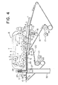
- the roller mechanism R is supported by a pair of said frames 24 positioned at its respective opposite sides, and each frame 24 is integrally connected to a pair of vertical shifting devices D, at at its front and rear ends respectively, by way of brackets 25 which form part of the devices D.
- a post 26 extends vertically through the centre of each device D, and is in threaded engagement with the bracket 25.
- a casing 51 of the device D is secured to the bracket 25, and is in telescopic sliding engagement with a base part 52, which is securely connected to an outer frame 32 of the belt conveyor mechanism.
- the post 26 is rotatable about its axis by a motor 27.
- a roller mechanism R is aranged to be moved vertically by devices similar to the devices D of Figure 4, but both the upper flight 9' of the entrance belt conveyor 18 and the upper flight 10 of the exit belt conveyor 20 are fixedly and immovably mounted. Therefore, when a desired thickness of dough sheet is to be produced, the roller mechanism R is moved vertically to set the spacing Tc between the upper flight of the exit belt conveyor 20 and the lower straight portion S of the roller mechanism. R. Such vertical movement of the roller mechanism R also changes the spacing Ta, since the position of the upper flight 9 of the entrance belt conveyor 10 is held unchanged.
- the upper flight 110 of an exit belt conveyor 120 is arranged to be movable vertically, in addition to the upper flight 109 of an entrance belt conveyor 118 being pivotable similarly to the device of Figure 4.
- a conveyor plate supporting arm 114 in Figure 5 is pivoted on a shaft which is mounted on the outer frame 32 of the belt conveyor mechanism, whilst in Figure 4 the arm 14 is pivoted on the shaft of one of the rollers of the exit belt conveyor 20.
- the setting of the spacing Tc is carried out by vertically adjusting the upper flight 110 of the exit belt conveyor 120, instead of vertically adjusting of the roller mechanism R as in the embodiment of Figure 4.
- the upper flight 110 is supported by a conveyor plate 128, the opposite ends of which are curved in order that the conveyor belt can run smoothly therearound.
- the ends are in fact formed by rollers 123 whose shafts are attached to the plate 128.
- the plate 128 is mounted on shafts 129 which are vertically movable by means of a motor 131 driving through gearing 130.
- a desired spacing Ta and/or a desired spacing Tc can be set by vertically adjusting the roller mechanism R and one of the upper flights of the entrance and exit belt conveyors, or alternatively by moving the upper flights of both the entrance and exit belt conveyors.
- neither the roller mechanism R nor the upper flight 9 and 10 of the entrance and exit belt conveyors, is provided with any means for moving them.
- neither the spacing Ta nor the spacing Tc is arranged to be adjustable.
- a strip of dough B fed into the apparatus is so thick that the dough strip on the upper flight 9 comes into contact with the rollers 2 before they begin their lower straight run, thereby resulting in an unnecessarily long contact length 1" as also seen in Figure 1, a protuberance B' will appear on the strip of dough B.
- the strip of dough may be spread in the widthwise direction while passing along the upper flight 9 of the entrance belt conveyor 18. As a result, a dough sheet of a good quality and a uniform width will not be produced.
- the upper flight 9 of the entrance belt conveyor 18 may be positioned parallel to the lower straight portion S of the roller mechanism R, in place of the arrangement shown in Figure 1, and that the upper flight 9 can then be modified, without any difficulty, to be vertically movable similarly to the upper flight 10 of the exit belt conveyor 120 in the embodiment of Figure 5.
- the thickness T 2 of the dough sheet to be produced is determined, and the spacing Tc is set, taking the resilience or restoring property of the dough into consideration, by rotating the motors 27 to vertically adjust the roller mechanism R.
- T 2 is practically equal to Tc
- T 2 is slightly greater than Tc. Therefore, when the product requires high precision in its thickness, T 2 should be carefully set after precisely measuring the resilience of the dough.
- V 2 is substantially equal to the speed of the exit conveyor belt, when the dough resilience is substantially zero.
- V 2 is slightly less than the speed of the exit conveyor belt.
- the values T 2' V 2 , and W 2 are now fed to an input unit 33, as input data.
- the sensor 23 measures the thickness T 1 and width W 1 of the strip of dough conveyed by the entrance belt conveyor 18 and transmits such information to the motor 16.
- the motor 16 rotates in response to the feeding of the information of the thickness T l , thereby causing the plate 15 to move vertically until the spacing Ta becomes equal to the dough thickness T 1 .
- V i x T 1 x W 1 is substantially equal to V 2 x T 2 x W 2 . Therefore, V 2 is automatically calculated by the computer 34 from the equation.
- a signal indicative of V 1 is transmitted from the computer 34 to the variable speed motor 17, thereby determining the speed of the entrance belt conveyor 18.
- the operation of the apparatus shown in Figure 5 is similar to that of Figure 4, except that the thickness T 2 is determined by rotating the motor 131 to vertically adjust the conveyor plate 128, while the thickness T 2 in the apparatus in Figure 4 is adjusted by the vertical movement of the roller mechanism R.
- the above relation can be inversed to provide the relation W 2 ⁇ W 1 .
- a dough sheet produced can have a predetermined width.
- a dough sheet having a desired thickness and/or width can be produced by including a resiliency coefficient peculiar to the dough in question, in the above equation.
- the spacing between the upper flight of the entrance belt conveyor and the lower straight portion of the roller mechanism can be changed to conform to the thickness of the strip of dough to be fed into the apparatus, whereby to stabilize the dough stretching effect.
Landscapes
- Engineering & Computer Science (AREA)
- Power Engineering (AREA)
- Life Sciences & Earth Sciences (AREA)
- Food Science & Technology (AREA)
- Manufacturing And Processing Devices For Dough (AREA)
- Bakery Products And Manufacturing Methods Therefor (AREA)
- Noodles (AREA)
- Diaphragms For Electromechanical Transducers (AREA)
- Containers And Plastic Fillers For Packaging (AREA)
- Chair Legs, Seat Parts, And Backrests (AREA)
Priority Applications (1)
| Application Number | Priority Date | Filing Date | Title |
|---|---|---|---|
| AT84303666T ATE45469T1 (de) | 1983-06-01 | 1984-05-31 | Strecken von teig. |
Applications Claiming Priority (2)
| Application Number | Priority Date | Filing Date | Title |
|---|---|---|---|
| JP58095816A JPS6052769B2 (ja) | 1983-06-01 | 1983-06-01 | 菓子生地等の延展方法及び装置 |
| JP95816/83 | 1983-06-01 |
Publications (3)
| Publication Number | Publication Date |
|---|---|
| EP0128015A2 true EP0128015A2 (de) | 1984-12-12 |
| EP0128015A3 EP0128015A3 (en) | 1985-10-09 |
| EP0128015B1 EP0128015B1 (de) | 1989-08-16 |
Family
ID=14147943
Family Applications (1)
| Application Number | Title | Priority Date | Filing Date |
|---|---|---|---|
| EP84303666A Expired EP0128015B1 (de) | 1983-06-01 | 1984-05-31 | Strecken von Teig |
Country Status (12)
| Country | Link |
|---|---|
| EP (1) | EP0128015B1 (de) |
| JP (1) | JPS6052769B2 (de) |
| KR (1) | KR890004892B1 (de) |
| AT (1) | ATE45469T1 (de) |
| AU (1) | AU545313B2 (de) |
| CA (1) | CA1222416A (de) |
| DD (1) | DD223912A5 (de) |
| DE (1) | DE3479386D1 (de) |
| ES (1) | ES533016A0 (de) |
| NZ (1) | NZ208260A (de) |
| PH (1) | PH26216A (de) |
| SU (1) | SU1336940A3 (de) |
Cited By (21)
| Publication number | Priority date | Publication date | Assignee | Title |
|---|---|---|---|---|
| EP0170436A1 (de) * | 1984-07-07 | 1986-02-05 | Rheon Automatic Machinery Co. Ltd. | Vorrichtung zur Streckung eines plastischen Rohmaterials |
| EP0173577A3 (en) * | 1984-08-31 | 1986-10-01 | Rheon Automatic Machinery Co. Ltd. | Apparatus for stretching plastic dough |
| EP0204490A1 (de) * | 1985-05-27 | 1986-12-10 | Rheon Automatic Machinery Co. Ltd. | Vorrichtung und Verfahren zur Herstellung von Hörnchen |
| EP0211669A1 (de) * | 1985-08-07 | 1987-02-25 | Rheon Automatic Machinery Co. Ltd. | Vorrichtung zum kontinuierlichen Strecken von Teig |
| US4850846A (en) * | 1987-07-31 | 1989-07-25 | G. Siempelkamp Gmbh & Co. | Apparatus for hot pressing mats used in the manufacture of chipboard, fiberboard and similar pressed board |
| EP0410818A1 (de) * | 1989-07-28 | 1991-01-30 | Rheon Automatic Machinery Co., Ltd. | Verfahren und Vorrichtung zum Strecken von Teig |
| EP0438923A1 (de) * | 1990-01-16 | 1991-07-31 | Rheon Automatic Machinery Co. Ltd. | Verfahren und Vorrichtung zum Ausstrecken von Teig |
| EP0442695A1 (de) * | 1990-02-16 | 1991-08-21 | Rheon Automatic Machinery Co. Ltd. | Streckwalzenvorrichtung für Teig |
| EP0453248A1 (de) * | 1990-04-17 | 1991-10-23 | Rheon Automatic Machinery Co., Ltd. | Verfahren und Vorrichtung zur Herstellung von Bahnen aus Brotteig |
| US5154941A (en) * | 1989-07-28 | 1992-10-13 | Rheon Automatic Machinery Co., Ltd. | Method for stretching dough |
| US5204123A (en) * | 1990-04-17 | 1993-04-20 | Rheon Automatic Machinery Co., Ltd. | Apparatus for manufacturing continuous sheets of bread dough |
| AU715199B2 (en) * | 1998-04-28 | 2000-01-20 | Rheon Automatic Machinery Co. Ltd. | An apparatus for stretching bread dough and the like |
| WO2000011958A1 (de) * | 1998-08-27 | 2000-03-09 | A. Fritsch Gmbh & Co. Kg | Verfahren, komponente und deren anordnung für die teigverarbeitung |
| US6955533B2 (en) | 2001-02-15 | 2005-10-18 | Rheon Automatic Machinery Co., Ltd. | Apparatus and method for extending food dough |
| US7205017B2 (en) | 2002-09-03 | 2007-04-17 | Rheon Automatic Machinery Co., Ltd. | Apparatus and method for beating and rolling a food dough belt |
| US7748621B2 (en) | 2005-06-06 | 2010-07-06 | International Business Machines Corporation | Method and system for dissemination of paperless transaction receipts in non-networked environments |
| US7910148B2 (en) | 2002-06-10 | 2011-03-22 | Rheon Automatic Machinery Co., Ltd. | Apparatus and method for beating and rolling a food dough belt |
| EP2225942A3 (de) * | 2009-03-06 | 2015-12-23 | Rheon Automatic Machinery Co., Ltd. | Vorrichtung zum Ausbreiten eines Nahrungsmittelteiges |
| IT202000008182A1 (it) * | 2020-04-17 | 2021-10-17 | Rollmatic S R L | Sfogliatrice automatica |
| EP3987935A1 (de) * | 2020-10-21 | 2022-04-27 | Fritsch Bakery Technologies GmbH & Co. KG | Vorrichtung zum bearbeiten von teig |
| EP4466999A1 (de) * | 2023-05-26 | 2024-11-27 | Fritsch Bakery Technologies GmbH & Co. KG | Teigverarbeitungsvorrichtung und verfahren |
Families Citing this family (6)
| Publication number | Priority date | Publication date | Assignee | Title |
|---|---|---|---|---|
| JPS61263374A (ja) * | 1985-05-17 | 1986-11-21 | Victor Co Of Japan Ltd | 入力信号切換装置 |
| JPS62193466A (ja) * | 1986-02-20 | 1987-08-25 | Fujitsu General Ltd | 受信周波数のプリセツト装置 |
| DE3641286C3 (de) * | 1986-12-03 | 1998-06-10 | Seewer Ag Burgdorf | Verfahren zum Ausrollen von Teig |
| JPH0228182U (de) * | 1988-08-10 | 1990-02-23 | ||
| ES2069485B1 (es) * | 1993-07-06 | 1998-07-01 | Puig Martinez Eulalia | Maquina formadora de barras de pan |
| JP5421619B2 (ja) | 2009-03-06 | 2014-02-19 | レオン自動機株式会社 | 食品生地の折り畳み積載方法及び装置 |
Family Cites Families (6)
| Publication number | Priority date | Publication date | Assignee | Title |
|---|---|---|---|---|
| FR1094103A (fr) * | 1950-04-13 | 1955-05-13 | Presse servant à produire des nappes continues de matière | |
| FR1085395A (fr) * | 1953-06-22 | 1955-02-02 | Machine à laminer et à rouler la pâte pour la fabrication des pains | |
| CH456134A (de) * | 1967-07-26 | 1968-05-15 | Jetzer Raimund | Verfahren zur Herstellung von Pressplatten |
| US4266920A (en) * | 1975-03-10 | 1981-05-12 | Rheon Automatic Machinery Co., Ltd. | Apparatus for continuously manufacturing multi-layered dough materials |
| JPS5225083A (en) * | 1975-08-22 | 1977-02-24 | Rheon Automatic Machinery Co | Developing apparatus for confection or bread dough and like |
| DE2735142C3 (de) * | 1977-08-04 | 1981-03-19 | Kurt 7218 Trossingen Held | Kontinuierlich arbeitende Presse |
-
1983
- 1983-06-01 JP JP58095816A patent/JPS6052769B2/ja not_active Expired
-
1984
- 1984-05-23 NZ NZ208260A patent/NZ208260A/en unknown
- 1984-05-24 AU AU28581/84A patent/AU545313B2/en not_active Ceased
- 1984-05-30 SU SU3745048A patent/SU1336940A3/ru active
- 1984-05-30 DD DD84263573A patent/DD223912A5/de unknown
- 1984-05-31 EP EP84303666A patent/EP0128015B1/de not_active Expired
- 1984-05-31 DE DE8484303666T patent/DE3479386D1/de not_active Expired
- 1984-05-31 AT AT84303666T patent/ATE45469T1/de not_active IP Right Cessation
- 1984-05-31 CA CA000455519A patent/CA1222416A/en not_active Expired
- 1984-05-31 ES ES533016A patent/ES533016A0/es active Granted
- 1984-06-01 PH PH30752A patent/PH26216A/en unknown
- 1984-06-01 KR KR1019840003052A patent/KR890004892B1/ko not_active Expired
Cited By (23)
| Publication number | Priority date | Publication date | Assignee | Title |
|---|---|---|---|---|
| EP0170436A1 (de) * | 1984-07-07 | 1986-02-05 | Rheon Automatic Machinery Co. Ltd. | Vorrichtung zur Streckung eines plastischen Rohmaterials |
| US4880375A (en) * | 1984-07-07 | 1989-11-14 | Rheon Automatic Machinery Co., Ltd. | Apparatus for stretching a plastic raw material |
| EP0173577A3 (en) * | 1984-08-31 | 1986-10-01 | Rheon Automatic Machinery Co. Ltd. | Apparatus for stretching plastic dough |
| EP0204490A1 (de) * | 1985-05-27 | 1986-12-10 | Rheon Automatic Machinery Co. Ltd. | Vorrichtung und Verfahren zur Herstellung von Hörnchen |
| EP0211669A1 (de) * | 1985-08-07 | 1987-02-25 | Rheon Automatic Machinery Co. Ltd. | Vorrichtung zum kontinuierlichen Strecken von Teig |
| US4850846A (en) * | 1987-07-31 | 1989-07-25 | G. Siempelkamp Gmbh & Co. | Apparatus for hot pressing mats used in the manufacture of chipboard, fiberboard and similar pressed board |
| US5154941A (en) * | 1989-07-28 | 1992-10-13 | Rheon Automatic Machinery Co., Ltd. | Method for stretching dough |
| EP0410818A1 (de) * | 1989-07-28 | 1991-01-30 | Rheon Automatic Machinery Co., Ltd. | Verfahren und Vorrichtung zum Strecken von Teig |
| US5164201A (en) * | 1989-07-28 | 1992-11-17 | Rheon Automatic Machinery Co., Ltd. | Apparatus for stretching dough |
| EP0438923A1 (de) * | 1990-01-16 | 1991-07-31 | Rheon Automatic Machinery Co. Ltd. | Verfahren und Vorrichtung zum Ausstrecken von Teig |
| EP0442695A1 (de) * | 1990-02-16 | 1991-08-21 | Rheon Automatic Machinery Co. Ltd. | Streckwalzenvorrichtung für Teig |
| EP0453248A1 (de) * | 1990-04-17 | 1991-10-23 | Rheon Automatic Machinery Co., Ltd. | Verfahren und Vorrichtung zur Herstellung von Bahnen aus Brotteig |
| US5204123A (en) * | 1990-04-17 | 1993-04-20 | Rheon Automatic Machinery Co., Ltd. | Apparatus for manufacturing continuous sheets of bread dough |
| AU715199B2 (en) * | 1998-04-28 | 2000-01-20 | Rheon Automatic Machinery Co. Ltd. | An apparatus for stretching bread dough and the like |
| WO2000011958A1 (de) * | 1998-08-27 | 2000-03-09 | A. Fritsch Gmbh & Co. Kg | Verfahren, komponente und deren anordnung für die teigverarbeitung |
| US6955533B2 (en) | 2001-02-15 | 2005-10-18 | Rheon Automatic Machinery Co., Ltd. | Apparatus and method for extending food dough |
| US7910148B2 (en) | 2002-06-10 | 2011-03-22 | Rheon Automatic Machinery Co., Ltd. | Apparatus and method for beating and rolling a food dough belt |
| US7205017B2 (en) | 2002-09-03 | 2007-04-17 | Rheon Automatic Machinery Co., Ltd. | Apparatus and method for beating and rolling a food dough belt |
| US7748621B2 (en) | 2005-06-06 | 2010-07-06 | International Business Machines Corporation | Method and system for dissemination of paperless transaction receipts in non-networked environments |
| EP2225942A3 (de) * | 2009-03-06 | 2015-12-23 | Rheon Automatic Machinery Co., Ltd. | Vorrichtung zum Ausbreiten eines Nahrungsmittelteiges |
| IT202000008182A1 (it) * | 2020-04-17 | 2021-10-17 | Rollmatic S R L | Sfogliatrice automatica |
| EP3987935A1 (de) * | 2020-10-21 | 2022-04-27 | Fritsch Bakery Technologies GmbH & Co. KG | Vorrichtung zum bearbeiten von teig |
| EP4466999A1 (de) * | 2023-05-26 | 2024-11-27 | Fritsch Bakery Technologies GmbH & Co. KG | Teigverarbeitungsvorrichtung und verfahren |
Also Published As
| Publication number | Publication date |
|---|---|
| EP0128015A3 (en) | 1985-10-09 |
| ES8504437A1 (es) | 1985-04-16 |
| EP0128015B1 (de) | 1989-08-16 |
| KR890004892B1 (ko) | 1989-11-30 |
| ATE45469T1 (de) | 1989-09-15 |
| NZ208260A (en) | 1986-06-11 |
| AU545313B2 (en) | 1985-07-11 |
| CA1222416A (en) | 1987-06-02 |
| KR850000189A (ko) | 1985-02-26 |
| DE3479386D1 (en) | 1989-09-21 |
| PH26216A (en) | 1992-04-01 |
| DD223912A5 (de) | 1985-06-26 |
| AU2858184A (en) | 1984-12-06 |
| ES533016A0 (es) | 1985-04-16 |
| SU1336940A3 (ru) | 1987-09-07 |
| JPS59224641A (ja) | 1984-12-17 |
| JPS6052769B2 (ja) | 1985-11-21 |
Similar Documents
| Publication | Publication Date | Title |
|---|---|---|
| EP0128015B1 (de) | Strecken von Teig | |
| EP0211669B1 (de) | Vorrichtung zum kontinuierlichen Strecken von Teig | |
| US4692107A (en) | Apparatus for continuously producing at a flow rate a strip of dough of constant dimensions | |
| US4902524A (en) | Method for continuously producing at a substantially constant flow rate a strip of dough of substantially uniform dimensions | |
| US4631017A (en) | Apparatus for rolling plastic dough | |
| EP0438923B1 (de) | Verfahren und Vorrichtung zum Ausstrecken von Teig | |
| RU1837775C (ru) | Тестораскаточное вальцовое устройство | |
| EP0173577B1 (de) | Vorrichtung zum Strecken einer plastischen Teigmasse | |
| EP0161076B1 (de) | Vorrichtung und Verfahren zur kontinuierlichen Herstellung eines Teigbandes mit ungefähr konstanter Breite und Strömungsgeschwindigkeit | |
| CA1243242A (en) | Apparatus for stretching a plastic raw material | |
| KR900004260A (ko) | 반죽물 조각을 말아서 반죽물 롤을 제조하기 위한 장치 및 방법 | |
| EP0647403B1 (de) | Vorrichtung zum mittigen Ausrichten von Hörnchenteigstücken | |
| JPH0494634A (ja) | 生地シートの積層装置 | |
| KR930006487B1 (ko) | 반죽 연신방법 및 장치 | |
| JP3464180B2 (ja) | 食品生地成形システム | |
| US20020110611A1 (en) | Apparatus and method for extending food dough | |
| US2136487A (en) | Bread loaf forming machine | |
| US5359833A (en) | Method of depositing extruded pieces of substances onto individual wrapping sheets and apparatus for carrying out the method | |
| JPH0121732B2 (de) | ||
| MXPA97005520A (en) | Controller for m roller | |
| JP2002306053A (ja) | 棒状パン生地の転圧延伸方法及び装置 |
Legal Events
| Date | Code | Title | Description |
|---|---|---|---|
| PUAI | Public reference made under article 153(3) epc to a published international application that has entered the european phase |
Free format text: ORIGINAL CODE: 0009012 |
|
| AK | Designated contracting states |
Designated state(s): AT BE CH DE FR GB IT LI LU NL SE |
|
| PUAL | Search report despatched |
Free format text: ORIGINAL CODE: 0009013 |
|
| AK | Designated contracting states |
Designated state(s): AT BE CH DE FR GB IT LI LU NL SE |
|
| 17P | Request for examination filed |
Effective date: 19860403 |
|
| 17Q | First examination report despatched |
Effective date: 19870527 |
|
| GRAA | (expected) grant |
Free format text: ORIGINAL CODE: 0009210 |
|
| AK | Designated contracting states |
Kind code of ref document: B1 Designated state(s): AT BE CH DE FR GB IT LI LU NL SE |
|
| REF | Corresponds to: |
Ref document number: 45469 Country of ref document: AT Date of ref document: 19890915 Kind code of ref document: T |
|
| REF | Corresponds to: |
Ref document number: 3479386 Country of ref document: DE Date of ref document: 19890921 |
|
| ITF | It: translation for a ep patent filed | ||
| ET | Fr: translation filed | ||
| PLBE | No opposition filed within time limit |
Free format text: ORIGINAL CODE: 0009261 |
|
| STAA | Information on the status of an ep patent application or granted ep patent |
Free format text: STATUS: NO OPPOSITION FILED WITHIN TIME LIMIT |
|
| 26N | No opposition filed | ||
| EPTA | Lu: last paid annual fee | ||
| EAL | Se: european patent in force in sweden |
Ref document number: 84303666.6 |
|
| REG | Reference to a national code |
Ref country code: GB Ref legal event code: IF02 |
|
| PGFP | Annual fee paid to national office [announced via postgrant information from national office to epo] |
Ref country code: SE Payment date: 20020508 Year of fee payment: 19 Ref country code: FR Payment date: 20020508 Year of fee payment: 19 |
|
| PGFP | Annual fee paid to national office [announced via postgrant information from national office to epo] |
Ref country code: AT Payment date: 20020513 Year of fee payment: 19 |
|
| PGFP | Annual fee paid to national office [announced via postgrant information from national office to epo] |
Ref country code: NL Payment date: 20020529 Year of fee payment: 19 Ref country code: GB Payment date: 20020529 Year of fee payment: 19 |
|
| PGFP | Annual fee paid to national office [announced via postgrant information from national office to epo] |
Ref country code: CH Payment date: 20020531 Year of fee payment: 19 |
|
| PGFP | Annual fee paid to national office [announced via postgrant information from national office to epo] |
Ref country code: LU Payment date: 20020605 Year of fee payment: 19 |
|
| PGFP | Annual fee paid to national office [announced via postgrant information from national office to epo] |
Ref country code: DE Payment date: 20020610 Year of fee payment: 19 |
|
| PGFP | Annual fee paid to national office [announced via postgrant information from national office to epo] |
Ref country code: BE Payment date: 20020717 Year of fee payment: 19 |
|
| PG25 | Lapsed in a contracting state [announced via postgrant information from national office to epo] |
Ref country code: LU Free format text: LAPSE BECAUSE OF NON-PAYMENT OF DUE FEES Effective date: 20030531 Ref country code: LI Free format text: LAPSE BECAUSE OF NON-PAYMENT OF DUE FEES Effective date: 20030531 Ref country code: GB Free format text: LAPSE BECAUSE OF NON-PAYMENT OF DUE FEES Effective date: 20030531 Ref country code: CH Free format text: LAPSE BECAUSE OF NON-PAYMENT OF DUE FEES Effective date: 20030531 Ref country code: BE Free format text: LAPSE BECAUSE OF NON-PAYMENT OF DUE FEES Effective date: 20030531 Ref country code: AT Free format text: LAPSE BECAUSE OF NON-PAYMENT OF DUE FEES Effective date: 20030531 |
|
| PG25 | Lapsed in a contracting state [announced via postgrant information from national office to epo] |
Ref country code: SE Free format text: LAPSE BECAUSE OF NON-PAYMENT OF DUE FEES Effective date: 20030601 |
|
| BERE | Be: lapsed |
Owner name: *RHEON AUTOMATIC MACHINERY CO. LTD Effective date: 20030531 |
|
| PG25 | Lapsed in a contracting state [announced via postgrant information from national office to epo] |
Ref country code: NL Free format text: LAPSE BECAUSE OF NON-PAYMENT OF DUE FEES Effective date: 20031201 |
|
| PG25 | Lapsed in a contracting state [announced via postgrant information from national office to epo] |
Ref country code: DE Free format text: LAPSE BECAUSE OF NON-PAYMENT OF DUE FEES Effective date: 20031202 |
|
| REG | Reference to a national code |
Ref country code: CH Ref legal event code: PL |
|
| GBPC | Gb: european patent ceased through non-payment of renewal fee |
Effective date: 20030531 |
|
| PG25 | Lapsed in a contracting state [announced via postgrant information from national office to epo] |
Ref country code: FR Free format text: LAPSE BECAUSE OF NON-PAYMENT OF DUE FEES Effective date: 20040130 |
|
| NLV4 | Nl: lapsed or anulled due to non-payment of the annual fee |
Effective date: 20031201 |
|
| EUG | Se: european patent has lapsed | ||
| REG | Reference to a national code |
Ref country code: FR Ref legal event code: ST |