EP0128015A2 - Dough stretching - Google Patents
Dough stretching Download PDFInfo
- Publication number
- EP0128015A2 EP0128015A2 EP84303666A EP84303666A EP0128015A2 EP 0128015 A2 EP0128015 A2 EP 0128015A2 EP 84303666 A EP84303666 A EP 84303666A EP 84303666 A EP84303666 A EP 84303666A EP 0128015 A2 EP0128015 A2 EP 0128015A2
- Authority
- EP
- European Patent Office
- Prior art keywords
- belt conveyor
- dough
- strip
- straight portion
- lower straight
- Prior art date
- Legal status (The legal status is an assumption and is not a legal conclusion. Google has not performed a legal analysis and makes no representation as to the accuracy of the status listed.)
- Granted
Links
Images


Classifications
-
- H—ELECTRICITY
- H02—GENERATION; CONVERSION OR DISTRIBUTION OF ELECTRIC POWER
- H02K—DYNAMO-ELECTRIC MACHINES
- H02K5/00—Casings; Enclosures; Supports
- H02K5/04—Casings or enclosures characterised by the shape, form or construction thereof
- H02K5/16—Means for supporting bearings, e.g. insulating supports or means for fitting bearings in the bearing-shields
- H02K5/173—Means for supporting bearings, e.g. insulating supports or means for fitting bearings in the bearing-shields using bearings with rolling contact, e.g. ball bearings
- H02K5/1732—Means for supporting bearings, e.g. insulating supports or means for fitting bearings in the bearing-shields using bearings with rolling contact, e.g. ball bearings radially supporting the rotary shaft at both ends of the rotor
-
- A—HUMAN NECESSITIES
- A21—BAKING; EDIBLE DOUGHS
- A21C—MACHINES OR EQUIPMENT FOR MAKING OR PROCESSING DOUGHS; HANDLING BAKED ARTICLES MADE FROM DOUGH
- A21C3/00—Machines or apparatus for shaping batches of dough before subdivision
- A21C3/02—Dough-sheeters; Rolling-machines; Rolling-pins
- A21C3/025—Dough-sheeters; Rolling-machines; Rolling-pins with one or more rollers moving perpendicularly to its rotation axis, e.g. reciprocally
- A21C3/027—Dough-sheeters; Rolling-machines; Rolling-pins with one or more rollers moving perpendicularly to its rotation axis, e.g. reciprocally with multiple rollers moving in a closed loop, e.g. in an orbital path; Planetary roller systems
-
- H—ELECTRICITY
- H02—GENERATION; CONVERSION OR DISTRIBUTION OF ELECTRIC POWER
- H02K—DYNAMO-ELECTRIC MACHINES
- H02K21/00—Synchronous motors having permanent magnets; Synchronous generators having permanent magnets
- H02K21/12—Synchronous motors having permanent magnets; Synchronous generators having permanent magnets with stationary armatures and rotating magnets
- H02K21/24—Synchronous motors having permanent magnets; Synchronous generators having permanent magnets with stationary armatures and rotating magnets with magnets axially facing the armatures, e.g. hub-type cycle dynamos
Landscapes
- Engineering & Computer Science (AREA)
- Power Engineering (AREA)
- Life Sciences & Earth Sciences (AREA)
- Food Science & Technology (AREA)
- Manufacturing And Processing Devices For Dough (AREA)
- Bakery Products And Manufacturing Methods Therefor (AREA)
- Noodles (AREA)
- Diaphragms For Electromechanical Transducers (AREA)
- Containers And Plastic Fillers For Packaging (AREA)
- Chair Legs, Seat Parts, And Backrests (AREA)
Abstract
Description
- This invention relates to the stretching of dough, such as cake dough, bread dough, noodle dough or the like, and particularly to an apparatus and method for continuously stretching a strip of dough, supplied in the shape of a thick layer, into a thin sheet.
- Apparatus for this purpose is well known from, for example the disclosures of U.S. Patent Specifications Nos. 4,056,346, 4,276,317, and 4,192,636. In these U.S. Patent Specifications there is disclosed an apparatus for continuously stretching a strip of dough, comprising:
- a belt conveyor mechanism comprising a plurality of belt conveyors arranged in series, the upper flights of which are adapted to underlie and support the strip of dough to carry it along a predetermined path, said series of belt conveyors including an entrance belt conveyor for feeding the strip of dough into the apparatus, and an exit belt conveyor for discharging the stretched strip of dough from the apparatus, the exit belt conveyor being movable faster than the entrance belt conveyor; and
- a roller mechanism comprising a plurality of fr(ely rotatable rollers movable in unison along an endless roller path, the peripheries of the moving rollers forming a closed envelope having a lowe straight portion spaced from and above the upper flights of said series of belt conveyors so that the rollers contact the strip of dough during teir movement along said lower straight portion the rollers being arranged to move in the same direction as the strip of dough when passing along said lower straight portion but at a speed greater han that of the said strip;
- the upper flight of the said exit belt conveyor being located substantially parallel to said lower straight portion to define a predetermined vertical spacing therebetween; and
- the upper flight of the entrance belt conveyor being located either parallel to, or in a tapering relationship with, said lower straight portion to define a predetemined vertical spacing between the starting point of said lower straight portion, or points adjacent thereto on the said envelope, and the upper flight of the entrance belt conveyor.
- In order to obtain a stretched dough sheet having a desired thickness, it is often required to control the vertical spacing between the upper flight of the exit belt conveyor and the lower straight portion of the said closed envelope. In known apparatus, the control of such spacing is carried out by vertical movement of the roller mechanism only. Such movement of the roller mechanism, however, naturally results in a change in the vertical spacing between the upper flight of the entrance belt conveyor and the above-mentioned lower straight portion. Consequently, if such spacing becomes too large, the strip of dough conveyed by the entrance belt conveyor tends to be wholly or partially out of contact with the rollers moving along their lower straight run, while if such space becomes too small the strip of dough tends to contact the rollers of the roller mechanism before they reach the lower straight run. Both of these circumstances will result in unsatisfactory dough stretching, and thus such a spacing control as this, relying only on vertical adjustment of the roller mechanism, is applicable only to cases where the thickness of the strip of dough supplied to the apparatus is within a limited range.
- One solution to this difficulty, proposed by the present invention, is to make the upper flight of the entrance belt conveyor pivotable up and down or movable vertically, so that the rollers moving along their lower straight run can be brought into proper contact with a strip of dough of whatever thickness conveyed by the entrance belt conveyor.
- Such an improvement can meet the requirements of providing simultaneously not only a desired vertical spacing between the upper flight of the exit belt conveyor and the said lower straight portion of the roller envelope, by adjusting the roller mechanism in known fashion, but also a desired vertical spacing between the upper flight of the entrance belt conveyor and the said lower straight portion.
- It will readily be understood that such requirements can also be met by changing the positions of the upper flights of both the entrance and exit belt conveyors, while the position of the roller mechanism is held unchanged.
- If circumstances require, it is also possible to meet the said requirements by first vertically adjusting the roller mechanism to provide a desired spacing between the lower straight portion thereof and the upper flight of the entrance belt conveyor, without moving the latter, in dependence on the thickness of the strip of dough to be fed into the apparatus; and then by vertically adjusting the upper flight of the exit belt conveyor to conform the vertical spacing between the said lower straight portion and the upper flight of the exit belt conveyor to a desired thickness of the dough sheet to be discharged out of the apparatus.
- Thus viewed from a first aspect the present invention provides an apparatus as already set forth above in connection with the prior art, characterized in that, of the roller mechanism and the said upper flights of the entrance and the exit belt conveyors, at least two of such three parts are arranged to be positionally adjustable in the vertical direction so as to provide a desired vertical spacing between the starting point of the said lower straight portion, or points adjacent thereto on the said envelope, and the upper flight of the entrance belt conveyor, and/or a desired vertical spacing between the upper flight of the exit belt conveyor and the said lower straight portion, depending on the thickness of the strip of dough to be fed into the apparatus and the desired thickness of the sheet of dough to be discharged out of the apparatus.
- In circumstances where there is no necessity for changing the thickness of the dough sheet to be discharged and only the thickness of the strip of dough fed into the apparatus is variable, the upper flight of the entrance belt conveyor can be the only member whose position is vertically adjustable.
- Thus viewed from another aspect of the present invention provides an apparatus again as set forth above, characterized in that the said upper flight of the entrance belt conveyor is positionally adjustable so as to provide a desired vertical spacing between the starting point of the said lower straight portion, or points adjacent thereto on the said envelope, and the upper flight of said entrance belt conveyor, depending on the thickness of the strip of dough to be fed into the apparatus.
- In a dough stretching apparatus of this kind, the strip of dough discharged out of the apparatus is usually formed so as to have substantially the same width as the strip of dough fed into the apparatus. It is possible, however, to produce a stretched sheethaving a width different from that of the unstretched strip. Viewed from yet another aspect the present invention provides a method of continuously stretching dough, comprising:
-
- (a) feeding a strip of dough onto the upper flight of an entrance belt conveyor constituting the first in a series of at least two belt conveyors;
- (b) applying pulling forces to the strip of dough by moving each of said series of belt conveyors at a speed greater then the adjacent upstream belt conveyor, while the strip of dough is repeatedly contacted by a plurality of freely rotatable rollers moving along a lower straight portion of an endless roller path, which - extends above said series of belt conveyors, and along which the rollers are moved in unison in the same direction as the strip of dough but at a speed greater than those of the belt conveyors; and
- (c) discharging the stretched dough by means of an exit belt conveyor constituting the last in said series of belt conveyors, the upper flight of the exit belt conveyor being located substantially parallel to the said lower straight portion of a closed envelope which is formed by the peripheries of the rollers moving along the said endless roller path;
- (d) setting a vertical spacing between the said upper flight of the exit belt conveyor and said lower straight portion of the endless roller path so as to obtain the desired thickness of the stretched dough sheet to be discharged, taking the restoring force of the dough into consideration;
- (e) setting the speed of the exit belt conveyor at a desired value;
- (f) measuring the thickness of the strip of dough to be fed into the system;
- (g) adjusting the vertical spacing between the said upper flight of the entrance belt conveyor and the starting point of the said lower straight portion, or points adjacent thereto on the said envelope, so as to conform to the thickness of the strip of dough to be fed in; and
- (h) controlling the speed of the entrance belt conveyor in proportion to the ratio of the desired thickness of the sheet of dough to be discharged to the thickness of the strip of dough to be fed in.
- In circumstances where the resilience of the dough being stretched is substantially zero, the thickness of the dough sheet to be produced is practically equal to the vertical spacing between the upper flight of the exit belt conveyor and the lower straight portion of the roller envelope. However, if the dough is very resilient, the thickness of the dough sheet to be produced is slightly greater than such spacing.
- Some embodiments of the invention will now be described by way of example and with reference to the accompanying drawings, in which:
- Figure 1 is a schematic side view of a known apparatus, in which neither a roller mechanism nor the upper flights of the entrance and exits belt conveyors is arranged to be positionally adjustable;
- Figures 2 and 3 are schematic side views of another known apparatus, in which only the roller mechanism is arranged to be adjustable;
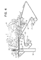
- Figure 4 is a schematic side view, partially broken away, of a first embodiment of an apparatus according to the present invention;
- Figure 5 is a schematic side view, partially broken away, of a second embodiment of the invention; and
- Figure 6 is a block diagram illustrating the operation of the apparatus.
- Referring to the embodiment of Figure 4, an apparatus according to the present invention comprises a roller mechanism R and a belt conveyor mechanism. The roller mechanism R comprises a plurality of rollers 2, each freely rotatably mounted on a shaft 3. The shafts 3 are attached to a
chain 4, which is trained under tension around a pair ofsprockets 7 and 8 mounted onshafts frame 24. The shafts 3, and thereby the rollers 2, are thus movable around an orbit X. During such movement of the rollers 2, the path of movement of the peripheries of the rollers defines a closed envelope as indicated by Y. The roller mechanism R is constructed so that the envelope Y has a lower straight portion S. - The belt conveyor mechanism is composed of two belt conveyors,-namely an
entrance belt conveyor 18 for feeding a strip of dough 1 into the apparatus, and anexit belt conveyor 20 for discharging the stretched sheet of dough from the apparatus. Theupper flights 9 and 10 of the entrance andexit belt conveyors - The upper flight 9 of the
entrance belt conveyor 18 is supported by aconveyor plate 15. Theplate 15 is connected to anarm 14, thedownstream end 12 of which is pivoted on the shaft of a roller of theexit belt conveyor 20, so that the inclination of theplate 15 can be changed relative to the lower straight portion S of the roller mechanism R. - A
cam 13 engages the underside of theplate 15 at its upstream end portion, the cam being mounted eccentrically on a shaft 11 which is rotatable about its axis by amotor 16 through gear means interconnecting these members. Thus, the upper flight 9 of theconveyor 18 can have its inclination changed by rotation of theeccentric cam 13, to increase or decrease the spacing Ta between the upper flight 9 and the lower straight portion S of the roller mechanism R. It should be noted throughout the description that the spacing Ta just mentioned corresponds to the distance between the top surface of the upper flight 9 and the starting point of the lower straight portion S, or points adjacent thereto, of the envelope Y. - Although in the illustrated embodiment the upper flight 9 of the
conveyor 18 is located in tapering relationship to the lower straight portionS of the roller mechanism R, and that the inclination of the said upper flight 9 is arranged to be changeable, the upper flight 9 may alternatively be arranged parallel to the lower straight portion S and be movable only in the vertical direction, without changing its angle relative to the portion S, for example by means of a device which will be described hereinafter with respect to the movement of theupper flight 10 of theexit belt conveyor 20 in Figure 5. - The
entrance belt conveyor 18 is driven by aroller 19 which is in turn driven by avariable speed motor 17 whose speed is arranged to be variable in response to external signals, whilst theexit belt conveyor 20 is driven by adrive roller 22 which is in turn driven by amotor 21. -
Reference numeral 23 designates a sensor for measuring the thickness T1 and the width W1 of strip of dough 1 fed into the apparatus. - The roller mechanism R is supported by a pair of
said frames 24 positioned at its respective opposite sides, and eachframe 24 is integrally connected to a pair of vertical shifting devices D, at at its front and rear ends respectively, by way ofbrackets 25 which form part of the devices D. Apost 26 extends vertically through the centre of each device D, and is in threaded engagement with thebracket 25. Acasing 51 of the device D is secured to thebracket 25, and is in telescopic sliding engagement with a base part 52, which is securely connected to anouter frame 32 of the belt conveyor mechanism. Thepost 26 is rotatable about its axis by amotor 27. - In the known apparatus shown in Figures 2 and 3, a roller mechanism R is aranged to be moved vertically by devices similar to the devices D of Figure 4, but both the upper flight 9' of the
entrance belt conveyor 18 and theupper flight 10 of theexit belt conveyor 20 are fixedly and immovably mounted. Therefore, when a desired thickness of dough sheet is to be produced, the roller mechanism R is moved vertically to set the spacing Tc between the upper flight of theexit belt conveyor 20 and the lower straight portion S of the roller mechanism. R. Such vertical movement of the roller mechanism R also changes the spacing Ta, since the position of the upper flight 9 of theentrance belt conveyor 10 is held unchanged. It is a rare occurence for the spacing Ta, as so set, to come close to the thicknesa T1 of the strip of dough fed into the apparatus, as will readily be seen from Figures 2 and 3, Figures 2 showing a case where the spacing Ta is too large and Figure 3 a case where it is too small. These circumstances will not change even if the upper flight 9 of theentrance belt conveyor 18 is fixedly located in a tapering relationship with the lower straight portion S of the roller mechanism R. - The embodiments of Figure 4 overcomes these difficulties of the known apparatus exemplified in Figures 2 and 3. Thus the change in the spacing Ta, which is caused in the known apparatus by the vertical movement of the roller-mechanism R, can readily be compensated for by pivoting the upper flight 9 of the
entrance belt conveyor 18, so as to conform the spacing Ta to the thickness T1 of the strip of dough to be fed into the apparatus. - It will readily be understood that such adustment of the spacing Ta can also be effect merely by moving the upper flight 9 vertically without pivoting it, although no means for carrying out such an operation is shown in the drawing. It will also be clear that such a procedure of pivoting (as well as vertically moving) the upper flight 9 can be applied to circumstances where the upper flight 9 is originally positioned parallel to the lower straight portion S of the roller mechanism R.
- In another embodiment of the invention, shown in Figure 5, the
upper flight 110 of anexit belt conveyor 120 is arranged to be movable vertically, in addition to theupper flight 109 of anentrance belt conveyor 118 being pivotable similarly to the device of Figure 4. The only difference in structure between the entrance belt conveyors of Figures 4 and 5 is that a conveyorplate supporting arm 114 in Figure 5 is pivoted on a shaft which is mounted on theouter frame 32 of the belt conveyor mechanism, whilst in Figure 4 thearm 14 is pivoted on the shaft of one of the rollers of theexit belt conveyor 20. - In the Figure 5 embodiment the setting of the spacing Tc is carried out by vertically adjusting the
upper flight 110 of theexit belt conveyor 120, instead of vertically adjusting of the roller mechanism R as in the embodiment of Figure 4. Thus theupper flight 110 is supported by aconveyor plate 128, the opposite ends of which are curved in order that the conveyor belt can run smoothly therearound. The ends are in fact formed byrollers 123 whose shafts are attached to theplate 128. Theplate 128 is mounted onshafts 129 which are vertically movable by means of amotor 131 driving throughgearing 130. - It will thus be understood that in apparatus according to the present invention, a desired spacing Ta and/or a desired spacing Tc can be set by vertically adjusting the roller mechanism R and one of the upper flights of the entrance and exit belt conveyors, or alternatively by moving the upper flights of both the entrance and exit belt conveyors.
- Another feature of the present invention will be be explained.
- In another known apparatus, shown in Figure 1, neither the roller mechanism R nor the
upper flight 9 and 10 of the entrance and exit belt conveyors, is provided with any means for moving them. In other words, neither the spacing Ta nor the spacing Tc is arranged to be adjustable. - In use of such known apparatus, if a strip of dough A fed into the apparatus is so thin that the dough strip on the upper flight 9 of the
entrance belt conveyor 18 can contact the rollers 2 only over the length 1_* as seen in Figure 1, the rolling distance over which the rollers 2 are effective is too short to sufficiently stretch the dough. In such a case, the strip of dough becomes uneven in thickness, and it may consequently be torn apart at the space between theupper flights 9 and 10 of the entrance andexit belt conveyors upper flight 10. - If on the other hand a strip of dough B fed into the apparatus is so thick that the dough strip on the upper flight 9 comes into contact with the rollers 2 before they begin their lower straight run, thereby resulting in an unnecessarily long contact length 1" as also seen in Figure 1, a protuberance B' will appear on the strip of dough B. This results in turbulent flow in the dough, whereby the dough will be subjected to undesirably great stress. Furthermore, the strip of dough may be spread in the widthwise direction while passing along the upper flight 9 of the
entrance belt conveyor 18. As a result, a dough sheet of a good quality and a uniform width will not be produced. - In circumstances where it is not required to produce stretch dough sheets of different thicknesses, and if the thickness of the strip of dough to be fed into the apparatus is varied, the above-mentioned problems inherent in the known apparatus of Figure 1 can be overcome simply by constructing the
entrance belt conveyor 18 so that is upper flight 9 is positionally adjustable. Although such an embodiment is not illustrated, it will readily be understood that the upper flight 9 of theentrance belt conveyor 18 of Figure 1 can be arranged to be pivotally adjustable by means similar to that shown in Figures 4 and 5, so that the spacing Ta can then be controlled to match the thickness of the strip of dough to be fed into the apparatus, thereby attaining the desired rolling distance 1. Thus a constant relationship can be maintained between the width WI of the strip of dough fed into the apparatus and that W2 of the.dough sheet produced by the apparatus. - It will also readily be understood that the upper flight 9 of the
entrance belt conveyor 18 may be positioned parallel to the lower straight portion S of the roller mechanism R, in place of the arrangement shown in Figure 1, and that the upper flight 9 can then be modified, without any difficulty, to be vertically movable similarly to theupper flight 10 of theexit belt conveyor 120 in the embodiment of Figure 5. - The operation of an apparatus according to the present invention will now be further explained with reference to Figures 4 and 6.
- First, the thickness T2 of the dough sheet to be produced is determined, and the spacing Tc is set, taking the resilience or restoring property of the dough into consideration, by rotating the
motors 27 to vertically adjust the roller mechanism R. Here it should be noted that when the dough resilience is substantially zero, T2 is practically equal to Tc, whilst that when the dough is very resilient, T2 is slightly greater than Tc. Therefore, when the product requires high precision in its thickness, T2 should be carefully set after precisely measuring the resilience of the dough. - Next, the speed V2 and width W2 of the dough sheet to be carried away by the
exit belt conveyor 20 are determined. V2 is substantially equal to the speed of the exit conveyor belt, when the dough resilience is substantially zero. When the dough is more resilient, however, V2 is slightly less than the speed of the exit conveyor belt. - The values T2' V2 , and W2 are now fed to an
input unit 33, as input data. Then, thesensor 23 measures the thickness T1 and width W1 of the strip of dough conveyed by theentrance belt conveyor 18 and transmits such information to themotor 16. Themotor 16 rotates in response to the feeding of the information of the thickness Tl, thereby causing theplate 15 to move vertically until the spacing Ta becomes equal to the dough thickness T1. - The above data Tl, T2, V21 W1 and W2 are fed to a
computer 34. When the dough resilience is substantially zero, Vi x T1 x W1 is substantially equal to V2 x T2 x W2. Therefore, V2 is automatically calculated by thecomputer 34 from the equation. A signal indicative of V1 is transmitted from thecomputer 34 to thevariable speed motor 17, thereby determining the speed of theentrance belt conveyor 18. - The operation of the apparatus shown in Figure 5 is similar to that of Figure 4, except that the thickness T2 is determined by rotating the
motor 131 to vertically adjust theconveyor plate 128, while the thickness T2 in the apparatus in Figure 4 is adjusted by the vertical movement of the roller mechanism R. - It will be readily understood that an apparatus according to the invention in which the upper flight of the entrance belt conveyor is the only member arranged to be adjustable, can also be operated similarly to the above.
- In cases where the dough resilience is substantially zero, assuming Wl=W2, the relation V1 x T1 = V 2 x T2 holds. It can be seen in this case that the dough flows regularly through the apparatus while maintaining a uniform width, and therefore dough can be stretched without generating any substantial turbulence therein.
- Further, when it is desired to increase the width W2 relative to W1, assuming both T1 and T2 are unchanged, a larger value should be selected for VI to satisfy the relation V1 x T1 > V2 x T2, since W2 > W1 in the equation V1 x T1 x W1 = V2 x T2 x W2. The above relation can be inversed to provide the relation W2 < W1. Thus a dough sheet produced can have a predetermined width.
- In cases where the dough is resilient, a dough sheet having a desired thickness and/or width can be produced by including a resiliency coefficient peculiar to the dough in question, in the above equation.
- It will be understood from the foregoing description that in use of apparatus according to the present invention, the spacing between the upper flight of the entrance belt conveyor and the lower straight portion of the roller mechanism can be changed to conform to the thickness of the strip of dough to be fed into the apparatus, whereby to stabilize the dough stretching effect.
- Also, in use of apparatus according to the invention, the ratio between the spacing Tc between the upper flight of the exit belt conveyor and the lower straight portion S of the roller mechanism and the spacing Ta between the upper flight of the entrance belt conveyor and the lower straight portion S of the roller mechanism is measured, the spacing Tc being adjusted if necessary to take the dough resilience into consideration, and depending on the value of this ratio, the ratio of the speed V2 of the exit belt conveyor to the speed V1 of the entrance belt conveyor is automatically set to satisfy the relation Vl x T1 = V2 x T2, V1 x T1 > V 2 x T 2, or V, x T1 < V2 x T2, thereby substantially eliminating the instability of the dough stretching effect which is inherent in the prior art apparatus, increasing the flexibility of the apparatus to accomodate itself to wide ranges of thickness and width of a dough sheet to be stretched, and generally facilitating operation of the apparatus.
characterised by:
Claims (8)
characterized in that
of the roller mechanism (R) and the said upper flights (9,10) of the entrance and exit belt conveyors (18,20), at least two of the such three parts are arranged to be positionally adjustable in the vertical direction so as to provide a desired vertical spacing (Ta) betwen the starting point of the said lower straight portion (5), or points adjacent thereto on the said envelope, and the upper flight of the entrance belt conveyor, and/or a desired vertical spacing (Tc) between the upper flight of the exit belt conveyor and the said lower straight portion, depending on the thickness (Tl) of the strip of dough to be fed into the apparatus and the desired thickness (T2) of the sheet of dough to be discharged out of apparatus.
characterized in that
the said upper flight (9) of the entrance belt conveyor (18) is positionally adjustable so as to provide a desired vertical spacing (Ta) between the starting point of said lower straight portion, or points adjacent thereto on the said envelope, and the upper flight (9) of said entrance belt conveyor (18), depending on the thickness (TI) of the strip of dough to be fed into the apparatus.
characterised by:
Priority Applications (1)
| Application Number | Priority Date | Filing Date | Title |
|---|---|---|---|
| AT84303666T ATE45469T1 (en) | 1983-06-01 | 1984-05-31 | STRETCHING OF DOUGH. |
Applications Claiming Priority (2)
| Application Number | Priority Date | Filing Date | Title |
|---|---|---|---|
| JP58095816A JPS6052769B2 (en) | 1983-06-01 | 1983-06-01 | Method and device for spreading confectionery dough, etc. |
| JP95816/83 | 1983-06-01 |
Publications (3)
| Publication Number | Publication Date |
|---|---|
| EP0128015A2 true EP0128015A2 (en) | 1984-12-12 |
| EP0128015A3 EP0128015A3 (en) | 1985-10-09 |
| EP0128015B1 EP0128015B1 (en) | 1989-08-16 |
Family
ID=14147943
Family Applications (1)
| Application Number | Title | Priority Date | Filing Date |
|---|---|---|---|
| EP84303666A Expired EP0128015B1 (en) | 1983-06-01 | 1984-05-31 | Dough stretching |
Country Status (12)
| Country | Link |
|---|---|
| EP (1) | EP0128015B1 (en) |
| JP (1) | JPS6052769B2 (en) |
| KR (1) | KR890004892B1 (en) |
| AT (1) | ATE45469T1 (en) |
| AU (1) | AU545313B2 (en) |
| CA (1) | CA1222416A (en) |
| DD (1) | DD223912A5 (en) |
| DE (1) | DE3479386D1 (en) |
| ES (1) | ES8504437A1 (en) |
| NZ (1) | NZ208260A (en) |
| PH (1) | PH26216A (en) |
| SU (1) | SU1336940A3 (en) |
Cited By (20)
| Publication number | Priority date | Publication date | Assignee | Title |
|---|---|---|---|---|
| EP0170436A1 (en) * | 1984-07-07 | 1986-02-05 | Rheon Automatic Machinery Co. Ltd. | Apparatus for stretching a plastic raw material |
| EP0173577A2 (en) * | 1984-08-31 | 1986-03-05 | Rheon Automatic Machinery Co. Ltd. | Apparatus for stretching plastic dough |
| EP0204490A1 (en) * | 1985-05-27 | 1986-12-10 | Rheon Automatic Machinery Co. Ltd. | An apparatus and method for producing croissants |
| EP0211669A1 (en) * | 1985-08-07 | 1987-02-25 | Rheon Automatic Machinery Co. Ltd. | Apparatus for continuously stretching dough |
| US4850846A (en) * | 1987-07-31 | 1989-07-25 | G. Siempelkamp Gmbh & Co. | Apparatus for hot pressing mats used in the manufacture of chipboard, fiberboard and similar pressed board |
| EP0410818A1 (en) * | 1989-07-28 | 1991-01-30 | Rheon Automatic Machinery Co., Ltd. | Method and apparatus for stretching dough |
| EP0438923A1 (en) * | 1990-01-16 | 1991-07-31 | Rheon Automatic Machinery Co. Ltd. | Method and apparatus for stretching dough |
| EP0442695A1 (en) * | 1990-02-16 | 1991-08-21 | Rheon Automatic Machinery Co. Ltd. | Dough stretching roller apparatus |
| EP0453248A1 (en) * | 1990-04-17 | 1991-10-23 | Rheon Automatic Machinery Co., Ltd. | Method and apparatus for manufacturing continuous sheets of bread dough |
| US5154941A (en) * | 1989-07-28 | 1992-10-13 | Rheon Automatic Machinery Co., Ltd. | Method for stretching dough |
| US5204123A (en) * | 1990-04-17 | 1993-04-20 | Rheon Automatic Machinery Co., Ltd. | Apparatus for manufacturing continuous sheets of bread dough |
| AU715199B2 (en) * | 1998-04-28 | 2000-01-20 | Rheon Automatic Machinery Co. Ltd. | An apparatus for stretching bread dough and the like |
| WO2000011958A1 (en) * | 1998-08-27 | 2000-03-09 | A. Fritsch Gmbh & Co. Kg | Method, components and the arrangement of said components for processing dough |
| US6955533B2 (en) | 2001-02-15 | 2005-10-18 | Rheon Automatic Machinery Co., Ltd. | Apparatus and method for extending food dough |
| US7205017B2 (en) | 2002-09-03 | 2007-04-17 | Rheon Automatic Machinery Co., Ltd. | Apparatus and method for beating and rolling a food dough belt |
| US7748621B2 (en) | 2005-06-06 | 2010-07-06 | International Business Machines Corporation | Method and system for dissemination of paperless transaction receipts in non-networked environments |
| US7910148B2 (en) | 2002-06-10 | 2011-03-22 | Rheon Automatic Machinery Co., Ltd. | Apparatus and method for beating and rolling a food dough belt |
| EP2225942A3 (en) * | 2009-03-06 | 2015-12-23 | Rheon Automatic Machinery Co., Ltd. | Food dough extending apparatus |
| IT202000008182A1 (en) * | 2020-04-17 | 2021-10-17 | Rollmatic S R L | AUTOMATIC SHEETER |
| EP3987935A1 (en) * | 2020-10-21 | 2022-04-27 | Fritsch Bakery Technologies GmbH & Co. KG | Device for processing dough |
Families Citing this family (7)
| Publication number | Priority date | Publication date | Assignee | Title |
|---|---|---|---|---|
| JPS61263374A (en) * | 1985-05-17 | 1986-11-21 | Victor Co Of Japan Ltd | Input signal switching device |
| JPS62193466A (en) * | 1986-02-20 | 1987-08-25 | Fujitsu General Ltd | Preset device for receiving frequency |
| DE3641286C3 (en) * | 1986-12-03 | 1998-06-10 | Seewer Ag Burgdorf | Process for rolling out dough |
| JPH0228182U (en) * | 1988-08-10 | 1990-02-23 | ||
| JP2727644B2 (en) * | 1989-04-25 | 1998-03-11 | 松下電器産業株式会社 | Receiver |
| ES2069485B1 (en) * | 1993-07-06 | 1998-07-01 | Puig Martinez Eulalia | BREAD BAR FORMING MACHINE |
| JP5421619B2 (en) | 2009-03-06 | 2014-02-19 | レオン自動機株式会社 | Method and apparatus for folding and loading food dough |
Citations (6)
| Publication number | Priority date | Publication date | Assignee | Title |
|---|---|---|---|---|
| FR1085395A (en) * | 1953-06-22 | 1955-02-02 | Dough rolling and rolling machine for bread making | |
| FR1094103A (en) * | 1950-04-13 | 1955-05-13 | Press for producing continuous webs of material | |
| GB1221127A (en) * | 1967-07-26 | 1971-02-03 | Raimund Jetzer | Improvements in and relating to continuous chain presses |
| FR2321240A2 (en) * | 1975-08-22 | 1977-03-18 | Rheon Automatic Machinery Co | DOUGH ROLLER |
| DE2735142A1 (en) * | 1977-08-04 | 1979-02-15 | Kurt Held | Double band continuous chipboard presses - where multiple bands are guided by flanges on rollers and held in alignment |
| US4266920A (en) * | 1975-03-10 | 1981-05-12 | Rheon Automatic Machinery Co., Ltd. | Apparatus for continuously manufacturing multi-layered dough materials |
-
1983
- 1983-06-01 JP JP58095816A patent/JPS6052769B2/en not_active Expired
-
1984
- 1984-05-23 NZ NZ208260A patent/NZ208260A/en unknown
- 1984-05-24 AU AU28581/84A patent/AU545313B2/en not_active Ceased
- 1984-05-30 DD DD84263573A patent/DD223912A5/en unknown
- 1984-05-30 SU SU3745048A patent/SU1336940A3/en active
- 1984-05-31 EP EP84303666A patent/EP0128015B1/en not_active Expired
- 1984-05-31 DE DE8484303666T patent/DE3479386D1/en not_active Expired
- 1984-05-31 CA CA000455519A patent/CA1222416A/en not_active Expired
- 1984-05-31 ES ES533016A patent/ES8504437A1/en not_active Expired
- 1984-05-31 AT AT84303666T patent/ATE45469T1/en not_active IP Right Cessation
- 1984-06-01 PH PH30752A patent/PH26216A/en unknown
- 1984-06-01 KR KR1019840003052A patent/KR890004892B1/en not_active IP Right Cessation
Patent Citations (6)
| Publication number | Priority date | Publication date | Assignee | Title |
|---|---|---|---|---|
| FR1094103A (en) * | 1950-04-13 | 1955-05-13 | Press for producing continuous webs of material | |
| FR1085395A (en) * | 1953-06-22 | 1955-02-02 | Dough rolling and rolling machine for bread making | |
| GB1221127A (en) * | 1967-07-26 | 1971-02-03 | Raimund Jetzer | Improvements in and relating to continuous chain presses |
| US4266920A (en) * | 1975-03-10 | 1981-05-12 | Rheon Automatic Machinery Co., Ltd. | Apparatus for continuously manufacturing multi-layered dough materials |
| FR2321240A2 (en) * | 1975-08-22 | 1977-03-18 | Rheon Automatic Machinery Co | DOUGH ROLLER |
| DE2735142A1 (en) * | 1977-08-04 | 1979-02-15 | Kurt Held | Double band continuous chipboard presses - where multiple bands are guided by flanges on rollers and held in alignment |
Cited By (23)
| Publication number | Priority date | Publication date | Assignee | Title |
|---|---|---|---|---|
| US4880375A (en) * | 1984-07-07 | 1989-11-14 | Rheon Automatic Machinery Co., Ltd. | Apparatus for stretching a plastic raw material |
| EP0170436A1 (en) * | 1984-07-07 | 1986-02-05 | Rheon Automatic Machinery Co. Ltd. | Apparatus for stretching a plastic raw material |
| EP0173577A2 (en) * | 1984-08-31 | 1986-03-05 | Rheon Automatic Machinery Co. Ltd. | Apparatus for stretching plastic dough |
| EP0173577A3 (en) * | 1984-08-31 | 1986-10-01 | Rheon Automatic Machinery Co. Ltd. | Apparatus for stretching plastic dough |
| EP0204490A1 (en) * | 1985-05-27 | 1986-12-10 | Rheon Automatic Machinery Co. Ltd. | An apparatus and method for producing croissants |
| EP0211669A1 (en) * | 1985-08-07 | 1987-02-25 | Rheon Automatic Machinery Co. Ltd. | Apparatus for continuously stretching dough |
| US4850846A (en) * | 1987-07-31 | 1989-07-25 | G. Siempelkamp Gmbh & Co. | Apparatus for hot pressing mats used in the manufacture of chipboard, fiberboard and similar pressed board |
| US5164201A (en) * | 1989-07-28 | 1992-11-17 | Rheon Automatic Machinery Co., Ltd. | Apparatus for stretching dough |
| EP0410818A1 (en) * | 1989-07-28 | 1991-01-30 | Rheon Automatic Machinery Co., Ltd. | Method and apparatus for stretching dough |
| US5154941A (en) * | 1989-07-28 | 1992-10-13 | Rheon Automatic Machinery Co., Ltd. | Method for stretching dough |
| EP0438923A1 (en) * | 1990-01-16 | 1991-07-31 | Rheon Automatic Machinery Co. Ltd. | Method and apparatus for stretching dough |
| EP0442695A1 (en) * | 1990-02-16 | 1991-08-21 | Rheon Automatic Machinery Co. Ltd. | Dough stretching roller apparatus |
| EP0453248A1 (en) * | 1990-04-17 | 1991-10-23 | Rheon Automatic Machinery Co., Ltd. | Method and apparatus for manufacturing continuous sheets of bread dough |
| US5204123A (en) * | 1990-04-17 | 1993-04-20 | Rheon Automatic Machinery Co., Ltd. | Apparatus for manufacturing continuous sheets of bread dough |
| AU715199B2 (en) * | 1998-04-28 | 2000-01-20 | Rheon Automatic Machinery Co. Ltd. | An apparatus for stretching bread dough and the like |
| WO2000011958A1 (en) * | 1998-08-27 | 2000-03-09 | A. Fritsch Gmbh & Co. Kg | Method, components and the arrangement of said components for processing dough |
| US6955533B2 (en) | 2001-02-15 | 2005-10-18 | Rheon Automatic Machinery Co., Ltd. | Apparatus and method for extending food dough |
| US7910148B2 (en) | 2002-06-10 | 2011-03-22 | Rheon Automatic Machinery Co., Ltd. | Apparatus and method for beating and rolling a food dough belt |
| US7205017B2 (en) | 2002-09-03 | 2007-04-17 | Rheon Automatic Machinery Co., Ltd. | Apparatus and method for beating and rolling a food dough belt |
| US7748621B2 (en) | 2005-06-06 | 2010-07-06 | International Business Machines Corporation | Method and system for dissemination of paperless transaction receipts in non-networked environments |
| EP2225942A3 (en) * | 2009-03-06 | 2015-12-23 | Rheon Automatic Machinery Co., Ltd. | Food dough extending apparatus |
| IT202000008182A1 (en) * | 2020-04-17 | 2021-10-17 | Rollmatic S R L | AUTOMATIC SHEETER |
| EP3987935A1 (en) * | 2020-10-21 | 2022-04-27 | Fritsch Bakery Technologies GmbH & Co. KG | Device for processing dough |
Also Published As
| Publication number | Publication date |
|---|---|
| ATE45469T1 (en) | 1989-09-15 |
| AU2858184A (en) | 1984-12-06 |
| SU1336940A3 (en) | 1987-09-07 |
| NZ208260A (en) | 1986-06-11 |
| CA1222416A (en) | 1987-06-02 |
| JPS6052769B2 (en) | 1985-11-21 |
| AU545313B2 (en) | 1985-07-11 |
| JPS59224641A (en) | 1984-12-17 |
| KR850000189A (en) | 1985-02-26 |
| EP0128015A3 (en) | 1985-10-09 |
| DD223912A5 (en) | 1985-06-26 |
| ES533016A0 (en) | 1985-04-16 |
| PH26216A (en) | 1992-04-01 |
| ES8504437A1 (en) | 1985-04-16 |
| EP0128015B1 (en) | 1989-08-16 |
| KR890004892B1 (en) | 1989-11-30 |
| DE3479386D1 (en) | 1989-09-21 |
Similar Documents
| Publication | Publication Date | Title |
|---|---|---|
| EP0128015B1 (en) | Dough stretching | |
| EP0211669B1 (en) | Apparatus for continuously stretching dough | |
| US4692107A (en) | Apparatus for continuously producing at a flow rate a strip of dough of constant dimensions | |
| US4902524A (en) | Method for continuously producing at a substantially constant flow rate a strip of dough of substantially uniform dimensions | |
| US4631017A (en) | Apparatus for rolling plastic dough | |
| EP0438923B1 (en) | Method and apparatus for stretching dough | |
| KR930010372B1 (en) | Method for manufacturing continuous sheets of bread dough | |
| RU1837775C (en) | Roller-type dough rolling device | |
| EP0173577B1 (en) | Apparatus for stretching plastic dough | |
| KR890003907B1 (en) | Apparatus for stretching a plastic raw material | |
| EP0161076B1 (en) | Apparatus and method for continuously producing a strip of dough having substantially constant transverse dimensions and flow rate | |
| KR900004260A (en) | Apparatus and method for manufacturing dough roll by rolling dough pieces | |
| EP0647403B1 (en) | Centre-aligning apparatus for croissant dough pieces | |
| JPH0494634A (en) | Device for laminating dough sheet | |
| KR930006487B1 (en) | Method and apparatus for stretching dough | |
| JP3464180B2 (en) | Food dough molding system | |
| US20020110611A1 (en) | Apparatus and method for extending food dough | |
| US2136487A (en) | Bread loaf forming machine | |
| JPH0121732B2 (en) | ||
| MXPA97005520A (en) | Controller for m roller | |
| JPH0331410B2 (en) | ||
| JP2002306053A (en) | Method and apparatus for rolling and extending rod-like bread dough |
Legal Events
| Date | Code | Title | Description |
|---|---|---|---|
| PUAI | Public reference made under article 153(3) epc to a published international application that has entered the european phase |
Free format text: ORIGINAL CODE: 0009012 |
|
| AK | Designated contracting states |
Designated state(s): AT BE CH DE FR GB IT LI LU NL SE |
|
| PUAL | Search report despatched |
Free format text: ORIGINAL CODE: 0009013 |
|
| AK | Designated contracting states |
Designated state(s): AT BE CH DE FR GB IT LI LU NL SE |
|
| 17P | Request for examination filed |
Effective date: 19860403 |
|
| 17Q | First examination report despatched |
Effective date: 19870527 |
|
| GRAA | (expected) grant |
Free format text: ORIGINAL CODE: 0009210 |
|
| AK | Designated contracting states |
Kind code of ref document: B1 Designated state(s): AT BE CH DE FR GB IT LI LU NL SE |
|
| REF | Corresponds to: |
Ref document number: 45469 Country of ref document: AT Date of ref document: 19890915 Kind code of ref document: T |
|
| REF | Corresponds to: |
Ref document number: 3479386 Country of ref document: DE Date of ref document: 19890921 |
|
| ITF | It: translation for a ep patent filed |
Owner name: SOCIETA' ITALIANA BREVETTI S.P.A. |
|
| ET | Fr: translation filed | ||
| PLBE | No opposition filed within time limit |
Free format text: ORIGINAL CODE: 0009261 |
|
| STAA | Information on the status of an ep patent application or granted ep patent |
Free format text: STATUS: NO OPPOSITION FILED WITHIN TIME LIMIT |
|
| 26N | No opposition filed | ||
| EPTA | Lu: last paid annual fee | ||
| EAL | Se: european patent in force in sweden |
Ref document number: 84303666.6 |
|
| REG | Reference to a national code |
Ref country code: GB Ref legal event code: IF02 |
|
| PGFP | Annual fee paid to national office [announced via postgrant information from national office to epo] |
Ref country code: SE Payment date: 20020508 Year of fee payment: 19 Ref country code: FR Payment date: 20020508 Year of fee payment: 19 |
|
| PGFP | Annual fee paid to national office [announced via postgrant information from national office to epo] |
Ref country code: AT Payment date: 20020513 Year of fee payment: 19 |
|
| PGFP | Annual fee paid to national office [announced via postgrant information from national office to epo] |
Ref country code: NL Payment date: 20020529 Year of fee payment: 19 Ref country code: GB Payment date: 20020529 Year of fee payment: 19 |
|
| PGFP | Annual fee paid to national office [announced via postgrant information from national office to epo] |
Ref country code: CH Payment date: 20020531 Year of fee payment: 19 |
|
| PGFP | Annual fee paid to national office [announced via postgrant information from national office to epo] |
Ref country code: LU Payment date: 20020605 Year of fee payment: 19 |
|
| PGFP | Annual fee paid to national office [announced via postgrant information from national office to epo] |
Ref country code: DE Payment date: 20020610 Year of fee payment: 19 |
|
| PGFP | Annual fee paid to national office [announced via postgrant information from national office to epo] |
Ref country code: BE Payment date: 20020717 Year of fee payment: 19 |
|
| PG25 | Lapsed in a contracting state [announced via postgrant information from national office to epo] |
Ref country code: LU Free format text: LAPSE BECAUSE OF NON-PAYMENT OF DUE FEES Effective date: 20030531 Ref country code: LI Free format text: LAPSE BECAUSE OF NON-PAYMENT OF DUE FEES Effective date: 20030531 Ref country code: GB Free format text: LAPSE BECAUSE OF NON-PAYMENT OF DUE FEES Effective date: 20030531 Ref country code: CH Free format text: LAPSE BECAUSE OF NON-PAYMENT OF DUE FEES Effective date: 20030531 Ref country code: BE Free format text: LAPSE BECAUSE OF NON-PAYMENT OF DUE FEES Effective date: 20030531 Ref country code: AT Free format text: LAPSE BECAUSE OF NON-PAYMENT OF DUE FEES Effective date: 20030531 |
|
| PG25 | Lapsed in a contracting state [announced via postgrant information from national office to epo] |
Ref country code: SE Free format text: LAPSE BECAUSE OF NON-PAYMENT OF DUE FEES Effective date: 20030601 |
|
| BERE | Be: lapsed |
Owner name: *RHEON AUTOMATIC MACHINERY CO. LTD Effective date: 20030531 |
|
| PG25 | Lapsed in a contracting state [announced via postgrant information from national office to epo] |
Ref country code: NL Free format text: LAPSE BECAUSE OF NON-PAYMENT OF DUE FEES Effective date: 20031201 |
|
| PG25 | Lapsed in a contracting state [announced via postgrant information from national office to epo] |
Ref country code: DE Free format text: LAPSE BECAUSE OF NON-PAYMENT OF DUE FEES Effective date: 20031202 |
|
| REG | Reference to a national code |
Ref country code: CH Ref legal event code: PL |
|
| GBPC | Gb: european patent ceased through non-payment of renewal fee |
Effective date: 20030531 |
|
| PG25 | Lapsed in a contracting state [announced via postgrant information from national office to epo] |
Ref country code: FR Free format text: LAPSE BECAUSE OF NON-PAYMENT OF DUE FEES Effective date: 20040130 |
|
| NLV4 | Nl: lapsed or anulled due to non-payment of the annual fee |
Effective date: 20031201 |
|
| EUG | Se: european patent has lapsed | ||
| REG | Reference to a national code |
Ref country code: FR Ref legal event code: ST |